

Link Lynx L2174, Lynx L2170, Lynx L2074 Product Manual

PRODUCT MANUAL
Lynx Receiver L2174, L2074, L2170
Document: CL140072 L2174 Manual Issue 2.5

1 CONTENTS
1 Contents .................................................................................................. 2
2 Products Covered ...................................................................................... 3
2.1 Manual Issue ................................................................................................................. 3
2.2 Firmware Version ........................................................................................................... 3
2.3 Support ......................................................................................................................... 3
3 Safety and Compliance ............................................................................... 4
3.1 CE Declaration of Conformity ........................................................................................... 5
4 Introduction .............................................................................................. 6
4.1 L2174 Internal Architecture ............................................................................................. 6
5 Specification ............................................................................................. 7
5.1 Demodulation ................................................................................................................ 7
5.2 Decoding ....................................................................................................................... 7
5.3 Inputs & Outputs ............................................................................................................ 8
5.4 Physical ........................................................................................................................ 8
6 Input / Output Connections ......................................................................... 9
6.1 RF1-4 inputs (L2174, L2074) ........................................................................................... 9
6.2 ASI IN .......................................................................................................................... 9
6.3 Frame lock input (L2174, L2170).................................................................................... 10
6.4 Video Outputs (L2174, L2170) ....................................................................................... 10
6.5 ASI out ....................................................................................................................... 10
6.6 Ctrl/Data ..................................................................................................................... 10
6.7 Audio 1 ....................................................................................................................... 11
6.8 Audio 2 ....................................................................................................................... 11
6.9 Camera Control/Alarm .................................................................................................. 12
6.10 Ethernet – Control ........................................................................................................ 12
6.11 Ethernet – Video over IP ............................................................................................... 12
7 Controls .................................................................................................. 12
7.1 Selection keys .............................................................................................................. 12
7.2 Menu scroll keys .......................................................................................................... 13
7.3 Hot Keys ..................................................................................................................... 13
7.4 LEDs ........................................................................................................................... 13
7.5 USB port ..................................................................................................................... 13
8 Operator Menus ........................................................................................ 13
9 Main Display ............................................................................................ 16
9.1 Demodulator Menus (L2174, L2074) ............................................................................... 16
9.2 Decoder Menus (L2174, L2170) ..................................................................................... 17
9.3 Stream Management Menu ............................................................................................ 18
9.4 System Menu ............................................................................................................... 19
9.5 Camera Control (L2174 only) ......................................................................................... 20
9.6 Web Browser Operation ................................................................................................ 21
10 Receiver Set-up ........................................................................................ 23
10.1 Self Test ..................................................................................................................... 23
10.2 Demodulation Options ................................................................................................... 23
10.3 Down Converter Type ................................................................................................... 25
10.4 Decoder ...................................................................................................................... 26
10.5 Deinterleaving ............................................................................................................. 26
10.6 Video over IP ............................................................................................................... 27
10.7 Decryption ................................................................................................................... 27
10.8 Independent and Customised Down Convertor operation ................................................... 27
11 Licences and Upgrades .............................................................................. 27
11.1 Licensing ..................................................................................................................... 27
11.2 Firmware Upgrades ...................................................................................................... 28
Document: CL140072 L2174 Manual Issue 2.5 Page 2 of 28

2 PRODUCTS COVERED
Part No.
Product Description
Details
L2174
Lynx Diversity Receiver
UHF input 70-860MHz
L2170
Lynx Decoder
ASI Input only
L2074
Lynx Diversity Demodulator
UHF input 70-860MHz
Issue
Date
Comments
1
November 2010
First Issue
1.1
December 2010
Minor formatting change
1.2
December 2010
Updated for V0009 release
2.0
September 2011
Updated for V0014 release including L2170 & L2074
2.1
November 2011
Minor corrections
2.2
January 2012
IP sections added
2.3
May 2012
Decryption added
2.4
December 2012
Multibandwidth LMS-T added
2.5
April 2014
Data connector part number corrected
2.1 Manual Issue
2.2 Firmware Version
This manual is based upon Firmware version V1024
Please see the website for details of latest firmware revision
2.3 Support
For more information, or for service / support please contact:
Worldwide – Advent (SATCOM) Link (Wireless Cameras)
UKsupport@vislink.com +44 (0) 1442 431410
Americas - Advent (SATCOM) Link (Wireless Cameras) MRC (Microwave)
USsupport@vislink.com +1 978 671 5929 or 888 777 9221
Asia Pacific - Advent (SATCOM) Link (Wireless Cameras) MRC (Microwave)
APACsupport@vislink.com +65 8189 3040
Document: CL140072 L2174 Manual Issue 2.5 Page 3 of 28

SERVICE PERSONNEL - CAUTION
DOUBLE POLE/NEUTRAL FUSING
3 SAFETY AND COMPLIANCE
Any mains power equipment must be earthed.
Connection and disconnection from the Mains supply is achieved through a detachable mains cord. This must
be of a suitable rating and cross-sectional area, and be approved to the relevant national standards. The cord or
its plug must be easily accessible to allow disconnection.
Replacement fuses must be of identical ratings to the original parts fitted, i.e. T5A H250
Operate the equipment within environmental limits and ensure as much ventilation as possible (normally Temp
0°C - 50°C <99% humidity).
Only authorised personnel should open the product and any repair or warranty will be invalidated if the seals
are broken.
The equipment has been designed to be CE compliant and Technical files are available on request.
Document: CL140072 L2174 Manual Issue 2.5 Page 4 of 28

3.1 CE Declaration of Conformity
Declaration of Conformity
RADIO & TELECOMMUNICATIONS TERMINAL EQUIPMENT DIRECTIVE
1999/5/EC
Issue 1 Date 02 November 2010
Equipment Covered:
Lynx Receivers L2174, L2170 & L2074
This equipment complies with the essential requirements of the above directive, as applied by the
following harmonised standards:
ETSI EN 301 489-1 EMC standard for radio equipment and services;
Part 1: Common technical requirements
ETSI EN 301 489-28 EMC standard for radio equipment and services;
Part 2: Specific conditions for wireless digital video links
ETSI EN 302 064 Harmonised EN for Wireless Video Links (WVL) operating in the 1,3 GHz
to 50 GHz frequency band
EN60950 Safety of Information Technology equipment
Manufacturer/Agent
Vislink International Ltd.
Vislink House
Maylands Avenue
Hemel Hempstead
Herts
HP2 7DE
United Kingdom
Certified by
H. Sadheura
Vislink International Ltd.
Document: CL140072 L2174 Manual Issue 2.5 Page 5 of 28
Inter-board connector
INTERCONNECT
Demod
FPGA
Decode
FPGA
Inter-board connector
CONTROLLER
Display
CPU
Eth 1
(ctrl)
USB
Eth 2
(VIP)
Kbd
Decode ctrl
tx/rx
PSU
Expansion
connector
L2174
conn
Video IP
CC/
Alm
Ctl/
Data
CC ctrl
ctrl
MPEG data out
CC return
Audio 1
Audio 2
A2
Individual leads
A1 (2xXLR)
A1 (2xXLR)
RF1
RF2
RF3 RF4
ASI
in
Phantom
Power
Tuner
Audio
decoder
(DSP)
SDI CV SDI CV
sync
Vid
1
Vid
2
F
lock
ASI
Tx
ASI
out
Tuner
Tuner
Tuner
Inter-board connector
Demod ctrl
tx/rx
Demod to decode ASI 1
18V
Demod to decode ASI 2
4 INTRODUCTION
The Lynx Receiver range are highly flexible, high performance products based on compact DVB-T and LMS-T
demodulators using VISLINK’s Maximum Ratio Combining diversity algorithm, and a combined HD/SD
decoder.
The ultra low delay MPEG2 SD/HD Decoder has been speed optimised to operate with the Link Research Ltd
family of MPEG2 Encoders, which utilise field encoding. This range of decoders will not support frame
decoding. A licensable upgrade will allow support for B-Frame or ‘Generic’ MPEG2 Decoding that will support
frame decoding, but at higher delay.
The Decoder can also be licensed to support H.264 decoding. This will be available in different levels from
Main Profile 4:2:0 8 bit, up to High Profile 4:2:2 10 bit.
The product range is based on three hardware variants: Demodulator-only (L2074), Decoder-only (L2170) and
Demodulator-Decoder (L2174). All other variants are licensable and therefore allow for field upgrades by
changing the license to enable extra features as required. Please contact VISLINK for details.
This document has been written primarily for the complete L2174 Receiver. Where there are major differences for the L2170 and
L2074 variants they will be indicated, however some minor differences may not always be documented.
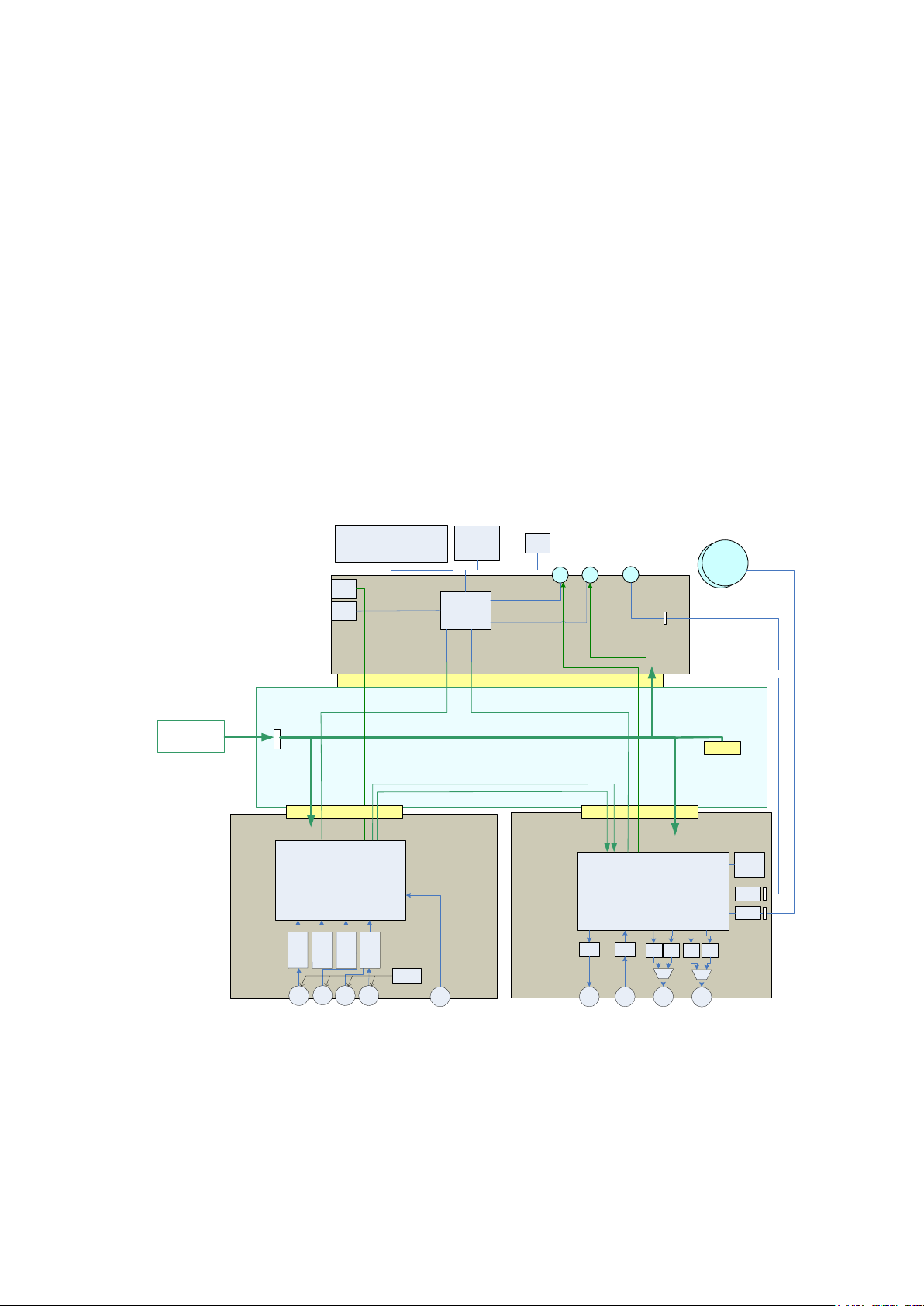
4.1 L2174 Internal Architecture
The L2174 is based on 3 main hardware components: Demodulator card, Decoder board and Controller board.
The L2074 & L2170 products do not have the Decoder and Demodulator boards fitted (respectively). Please
note that upgrading one of these to a full L2174 requires the unit to be returned to VISLINK.
As shown in the block diagram above, the Demodulator board generates an ASI stream from the RF inputs
and/or the external ASI, then passes this to the Decoder board to generate the Video and Audio outputs. In
addition, the Decoder extracts embedded (or ’wayside’) RS232 data if it is present in the transmission, as well as
return data from a VISLINK Camera Control System. There are 2 ASI connections between the boards to
allow extra flexibility in how the unit is configured (see later).
Video-over-IP functionality is all performed in the Demodulator card in the L2174 and L2074; the external
Ethernet connection is routed to this card and any ASI routing is performed between the two boards as
required. The L2170 uses the Decoder card for IP functionality.
Document: CL140072 L2174 Manual Issue 2.5 Page 6 of 28

5 SPECIFICATION
5.1 Demodulation
Modes supported (some are dependent on licences):
DVB-T:
6/7/8MHz bandwidth
QPSK/16QAM/64QAM
FEC 1/2, 2/3, 3/4, 5/6, 7/8
Guard Interval 1/32, 1/16, 1/8, 1/4
LMS-T:
Single and Dual Pedestals of 3, 4, 5, 6, 7, 8, 10 & 12MHz bandwidths
QPSK/16QAM
FEC 2/3
Guard Interval 1/8, 1/16
General:
Receiver performance meets or exceeds ES 202 239 in DVB-T mode (typical sensitivity -93dBm
@DVB-T QPSK 1/2)
5.2 Decoding
Video Formats supported:
SD: 625i50; 525i59
HD: 720p50; 720p59; 720p60; 1080i50; 1080i59; 1080i60; 1080p23; 1080p24; 1080p25; 1080p29;
1080p30; 1080psf23; 1080psf24; 1080psf25; 1080psf29; 1080psf30
HD Horizontal Resolution support (1080 line) : 1920, 1440*, 1280*, 960*
HD Horizontal Resolution support (720 line): 1280, 640*
SD Horizontal Resolution support (576/480 line): 720, 704*, 640*, 540*, 528*, 480*, 360*, 352*
* Not supported in Low Delay mode
(other resolutions will work but artefacts may be observed)
Chroma Format : 420 / 422
Bit Depth : 8bit (MPEG2); 8/9/10 bit (H.264)
Maximum Bit Rate : 80Mbit (MPEG2)
Audio Formats supported :
MPEG-1 Layer 1 20-bit 48kHz
MPEG-1 Layer 2 20-bit 48kHz
SMPTE 302M 20-bit 2 channel 48hHz 8ms frame
Document: CL140072 L2174 Manual Issue 2.5 Page 7 of 28

5.3 Inputs & Outputs
Summary (details in section 6):
4 x UHF input 70MHz to 860MHz, combined using Maximal Ratio Combining (MRC). Not L2170.
1 x ASI input (complies with ISO/IEC 13818-2 – 188byte mode)
1 x Frame lock input (Black/Burst or Trilevel). Not L2074
2 x Video outputs (CVBS/SD/HDSDI). Not L2074
1 x ASI output (complies with ISO/IEC 13818-2 – 188byte mode). 2 outputs on L2074
2 Audio channel outputs (analogue or digital). Not active in L2074
Data channel output. Not active in L2074
Video over IP connection (Ethernet RJ45)
IP control connection (Ethernet RJ45)
L1255 Camera Control Transmitter connection. Not active in L2074
5.4 Physical
CAUTION
Size
Height 44mm, Width 210mm, Depth 375mm - including rear panel connectors
Small form 1U, ½ width 19” rack mount
Weight
~1.2kg
Operating temperature range
Ambient 0ºC to +50ºC
Power
AC input option 90 VAC to 264 VAC 50Hz to 60Hz; max current 1A(rms)
DC input option 9 VDC to 36 VDC (-ve chassis earth); max current 10A
70Watts excluding the downconverters requirements.
90Watts max allowing for downconverters and cables.
(
L2170
- 45W;
: the side ventilation grilles must be kept clear to allow adequate airflow.
L2074
- 30W, not including downconverters)
Document: CL140072 L2174 Manual Issue 2.5 Page 8 of 28
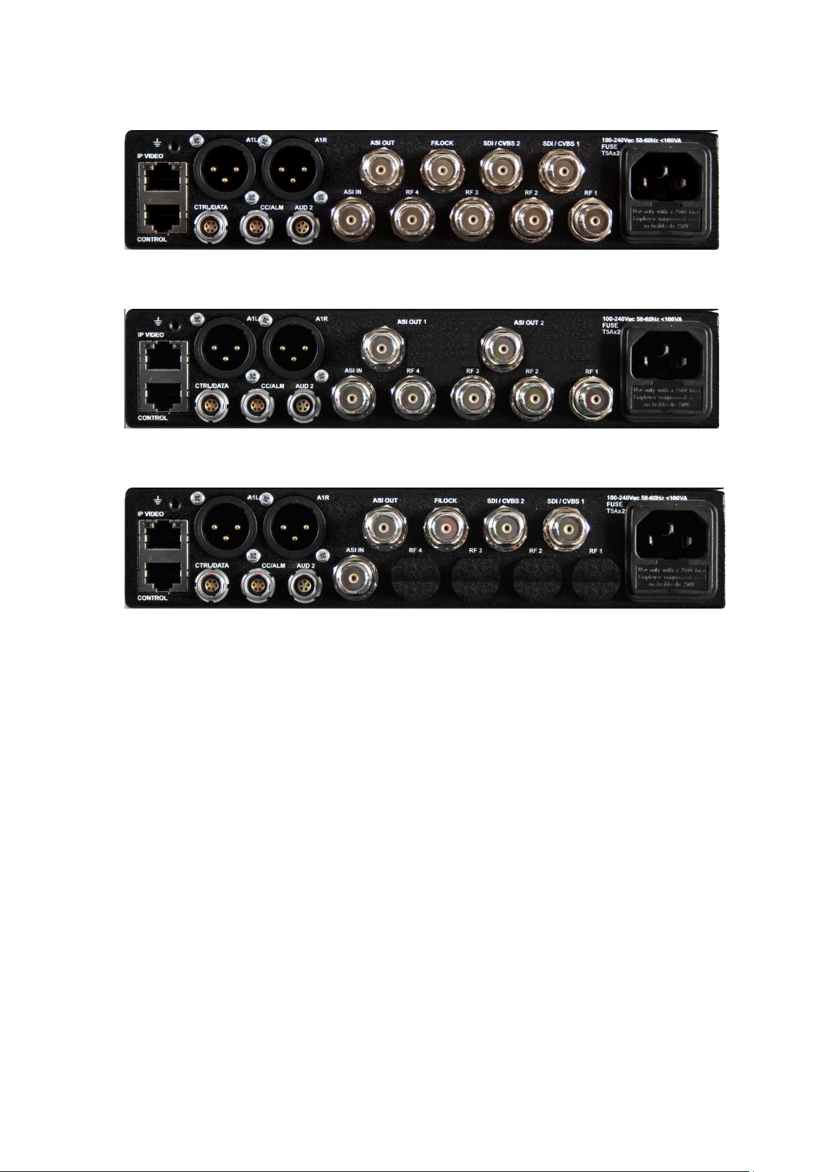
6 INPUT / OUTPUT CONNECTIONS
L2174
L2074
L2170
6.1 RF1-4 inputs (L2174, L2074)
75Ω BNC type chassis connector
(if only 2 inputs licensed, inputs 3 & 4 are non-operational)
Note:- When operating in Dual Pedestal LMS-T(D) RF 1 & 2 are used for connection to the two down
convertors. Demodulator settings for 1 & 2 should also be used to configure the appropriate RF inputs.
UHF input 70MHz to 860MHz.
Receiver performance meets or exceeds ES 202 239 in DVB-T mode (typical sensitivity -93dBm
@DVB-T QPSK 1/2)
Max input (damage level): 2W (CW)
For configuration please refer to 9.1 Demodulator Menu
Note:-
These inputs can have +20VDC output (set in Unit/LNB Power) to power the external down converter;
limited to 400mA per connector, short circuit protected.
In Triax mode, inputs 1 & 2 are used in Single mode; in Dual mode the second system is added to inputs 3 & 4.
6.2 ASI IN
75Ω BNC chassis mounted socket. Complies with ISO/IEC 13818-2 – 188byte mode.
ASI input to the Decoder, Packet diversity block, ASI output connector, or Video-IP block.
Document: CL140072 L2174 Manual Issue 2.5 Page 9 of 28
 Loading...