

Link LB20 Series Installation Instructions Manual
LB20 SERIES RAMPS
FEB 07, 2018
78510002
INSTALLATION INSTRUCTIONS
Link Mfg. Ltd.
223 15th St. N.E.
Sioux Center, IA USA
51250-2120
(712) 722-4868
Fax (712) 722-4779
QUESTIONS?
CALL CUSTOMER
SERVICE
1-800-248-3057
www.linkmfg.com

2
CAUTION
1. INTRODUCTION
Thank you for choosing a Link Cargo Management Products LB20 Ramp. We want to help you to get the best
results from the ramp and to operate it safely. This manual contains information to assist you with its installation.
The manual is intended solely for use with this product.
All information in this manual is based on the latest information available at the time of printing. Link
Manufacturing reserves the right to change its products or manuals at any time without notice. Contact Link CMP
at (800) 248-3057 for information on recent changes to products.
Damaged components should be returned to Link with a pre-arranged Returned Goods Authorization (RGA)
number through the Customer Service Department. The damaged component may then be replaced if in
compliance with warranty conditions.
2. SAFE WORKING PRACTICES:
3. INSTALLATION GUIDELINES
4.1. In order for this LB20 Ramp to operate properly, it must operate in the parameters specified by Link.
4.2. The installer must verify the Ramp is configured properly.
4.3. No alteration of any Link Ramp components are permitted without proper authorization from qualified
Link personnel.
IMPORTANT: IT IS IMPORTANT THAT THE ENTIRE INSTALLATION INSTRUCTIONS BE READ
THOROUGHLY BEFORE PROCEEDING WITH RAMP INSTALLATION.
• Wear appropriate gloves, eyeglasses, ear protection, and other safety equipment when handling parts.
• Practice safe lifting procedures. Consider size, shape, and weight of assemblies. Obtain help or the assis-
tance of a crane when lifting heavy assemblies. Make certain the path of travel is clear.
WARNING
• Proper tightening of fasteners is important to the performance and safety of this product.
• Make certain the vehicle is in placed in park on a flat surface, and the parking brake is engaged.
WARNING
• To insure safe operation, ramp shall not be operated without installation of pinch point guards and handles.
• See FIG 7 & 8 for proper installation procedure.
3
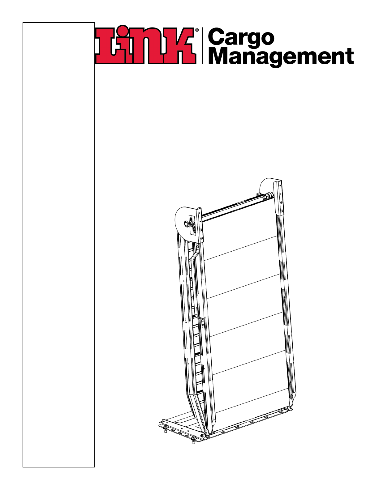
LATCH BRACKET ASSEMBLY (skip to Page 4 for lift assist assembly instructions)
1. Attach the Latch Bracket to the Rear Mount Plate using the two 1/4” X 1/2” Hex bolts, and the 1/4” hex nut
rear hole.
2. Attach the Keeper Latch to the Bumper Plate using the two 1/4” X 3/4” Pan head screws. 1/4” Flat washers,
and 1/4” hex nuts. (See FIG. 2)
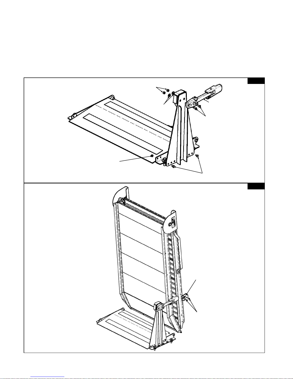
3. Attach the Ramp to the Rear mount plate by sliding the two Hinge Pins towards the center of the Ramp
aligning them to the mount plate and releasing.
4. Attach the Keeper Bracket to the side of the Ramp using the two 1/4” X 3/4” Pan head screws. (See FIG. 3)
LINK® MODEL “LB20”
KEEPER
BRACKET
1/4” X 3/4”
PANHEAD
SCREW
1/4 X 1/2 HEX BOLT
1/4” HEX NUT
1/4” HEX NUT
1/4” FLAT
WASHER
KEEPER
LATCH
1/4” X 3/4”
PANHEAD
SCREW
FIG. 2
FIG. 3
 Loading...