

Page 1
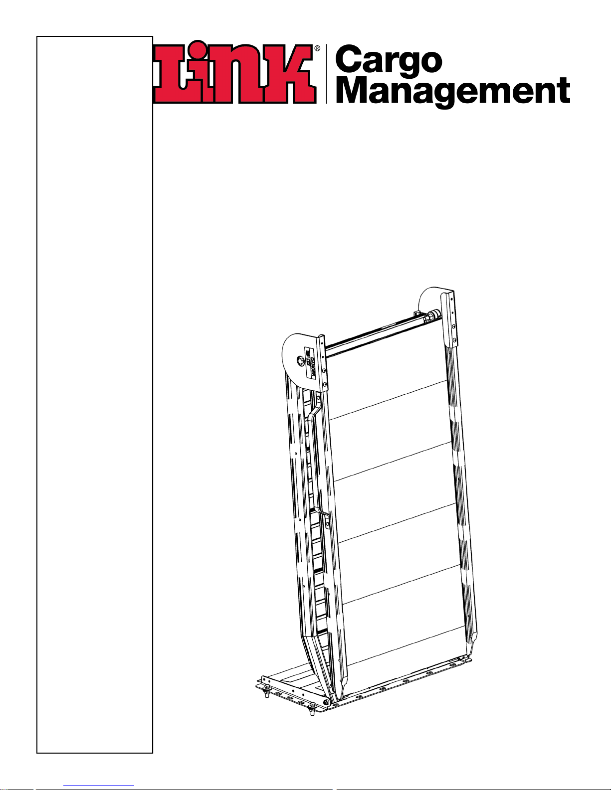
LB20 SERIES RAMPS
FEB 07, 2018
78510002
INSTALLATION INSTRUCTIONS
Link Mfg. Ltd.
223 15th St. N.E.
Sioux Center, IA USA
51250-2120
(712) 722-4868
Fax (712) 722-4779
QUESTIONS?
CALL CUSTOMER
SERVICE
1-800-248-3057
www.linkmfg.com
Page 2

2
CAUTION
1. INTRODUCTION
Thank you for choosing a Link Cargo Management Products LB20 Ramp. We want to help you to get the best
results from the ramp and to operate it safely. This manual contains information to assist you with its installation.
The manual is intended solely for use with this product.
All information in this manual is based on the latest information available at the time of printing. Link
Manufacturing reserves the right to change its products or manuals at any time without notice. Contact Link CMP
at (800) 248-3057 for information on recent changes to products.
Damaged components should be returned to Link with a pre-arranged Returned Goods Authorization (RGA)
number through the Customer Service Department. The damaged component may then be replaced if in
compliance with warranty conditions.
2. SAFE WORKING PRACTICES:
3. INSTALLATION GUIDELINES
4.1. In order for this LB20 Ramp to operate properly, it must operate in the parameters specified by Link.
4.2. The installer must verify the Ramp is configured properly.
4.3. No alteration of any Link Ramp components are permitted without proper authorization from qualified
Link personnel.
IMPORTANT: IT IS IMPORTANT THAT THE ENTIRE INSTALLATION INSTRUCTIONS BE READ
THOROUGHLY BEFORE PROCEEDING WITH RAMP INSTALLATION.
• Wear appropriate gloves, eyeglasses, ear protection, and other safety equipment when handling parts.
• Practice safe lifting procedures. Consider size, shape, and weight of assemblies. Obtain help or the assis-
tance of a crane when lifting heavy assemblies. Make certain the path of travel is clear.
WARNING
• Proper tightening of fasteners is important to the performance and safety of this product.
• Make certain the vehicle is in placed in park on a flat surface, and the parking brake is engaged.
WARNING
• To insure safe operation, ramp shall not be operated without installation of pinch point guards and handles.
• See FIG 7 & 8 for proper installation procedure.
Page 3
3
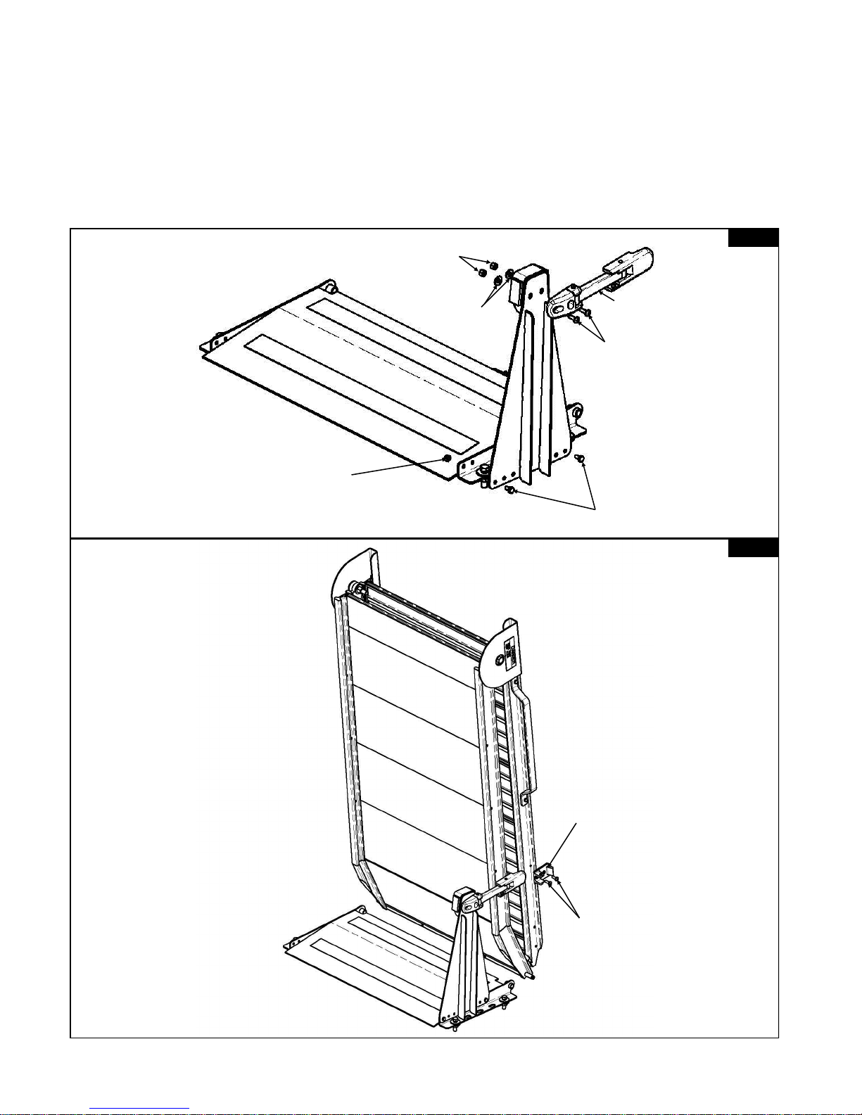
LATCH BRACKET ASSEMBLY (skip to Page 4 for lift assist assembly instructions)
1. Attach the Latch Bracket to the Rear Mount Plate using the two 1/4” X 1/2” Hex bolts, and the 1/4” hex nut
rear hole.
2. Attach the Keeper Latch to the Bumper Plate using the two 1/4” X 3/4” Pan head screws. 1/4” Flat washers,
and 1/4” hex nuts. (See FIG. 2)
3. Attach the Ramp to the Rear mount plate by sliding the two Hinge Pins towards the center of the Ramp
aligning them to the mount plate and releasing.
4. Attach the Keeper Bracket to the side of the Ramp using the two 1/4” X 3/4” Pan head screws. (See FIG. 3)
LINK® MODEL “LB20”
KEEPER
BRACKET
1/4” X 3/4”
PANHEAD
SCREW
1/4 X 1/2 HEX BOLT
1/4” HEX NUT
1/4” HEX NUT
1/4” FLAT
WASHER
KEEPER
LATCH
1/4” X 3/4”
PANHEAD
SCREW
FIG. 2
FIG. 3
Page 4
4
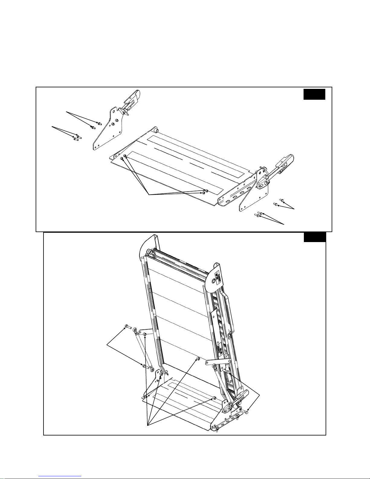
1/2” X 1 3/4”
HEX BOLTS
1/2”
HEX NUTS
1/2” X 1 3/4”
HEX BOLTS
LIFT ASSIST ASSEMBLY
1. Attach the Latch Mount Plate to the Rear Mount Plate using eight 1/4” X 1/2” Hex bolts, and four 1/4” hex
nuts rear hole. (See FIG. 4)
2. Attach the Ramp to the Rear mount plate by sliding the two Hinge Pins towards the center of the Ramp
aligning them to the mount plate and releasing.
3. Attach the two Tie Rods to the Latch Mount Plate and Torque Arms using the four 1/2” X 1 3/4” hex bolts
FIG. 4
FIG. 5
1/4” HEX NUTS
1/4” X 1/2”
HEX BOLTS
1/4” X 1/2” HEX
BOLTS
1/4” X 3/4”
HEX BOLTS
1/4” X 3/4”
HEX BOLTS
Page 5
5
Review the Parts Lists on Pages 6 and 7 to become familiar with the different components of your LB20.
Be sure all items were included before beginning assembly.
IMPORTANT: Installation of the LB20 will vary depending on what type of vehicle you have and how you
have it set up. Due to variables in different vehicles, the fit of the LB20 should be evaluated before beginning
installation. Some vehicles with a spare tire winch hoist will have a crank insert location in the rear of
the vehicle. Do not mount the ramp plate over this feature unless losing access to it is acceptable in
your application.
A. The LB20 Ramp is shipped partially assembled. Complete the assembly of the LB20 before beginning
installation. (See Page 3 for Latch Bracket assembly details, and Page 4 for Lift Assist assembly details.)
B. Before starting installation, place the LB20 in position and check all clearance issues. Be sure there is
adequate clearance between the LB20 and the van components (doors, door opening, etc.) Remember:
You will need access to both the ramp handle and the lever assisted latch if so equipped.
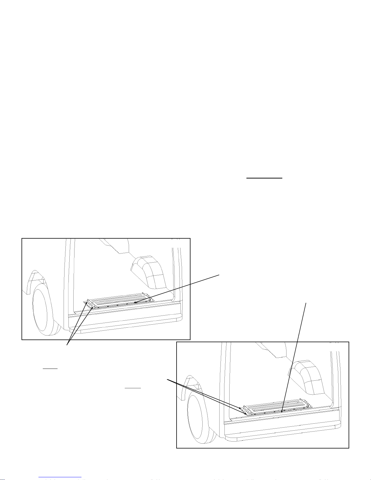
C. Once positioned, mark the 4 slots to be used for mounting the ramp as indicated in FIG. 1.For ProMaster
and Transit vans see FIG. 2. Set aside the ramp and the mount plate. Important: Before drilling,
double check that these holes are accessible and will not damage important van components.
Check under van to ensure no damage will occur in that area.
D. Drill four 29/64” holes.
E. Bolt the Ramp Mount Plate into place using the supplied 7/16” x 1 1/2” hex bolts, 7/16” flat washers, and
7/16” hex nuts
F. Confirm smooth operation and clearances.
RAMP INSTALLATION
7/16” X 1 1/2” HEX BOLTS
SHOULD BE PLACE AS
CLOSE TO FRONT AND
REAR INNER MOUNTING
SLOTS OF MOUNT PLATE
AS POSSIBLE.
RAMP SHOULD
BE PLACED AS
NEAR TO REAR
DOOR AS POSSIBLE WHILE
INSURING
PROPER DOOR
CLOSURE AND
CLEARANCE.
FIG. 1
FIG. 2
7/16” X 1 1/2” HEX BOLTS
SHOULD BE PLACE AS
CLOSE TO FRONT AND
REAR OUTER MOUNTING
SLOTS OF MOUNT PLATE
AS POSSIBLE.
RAMP SHOULD
BE PLACED AS
NEAR TO REAR
DOOR AS POSSIBLE WHILE
INSURING
PROPER DOOR
CLOSURE AND
CLEARANCE.
Page 6
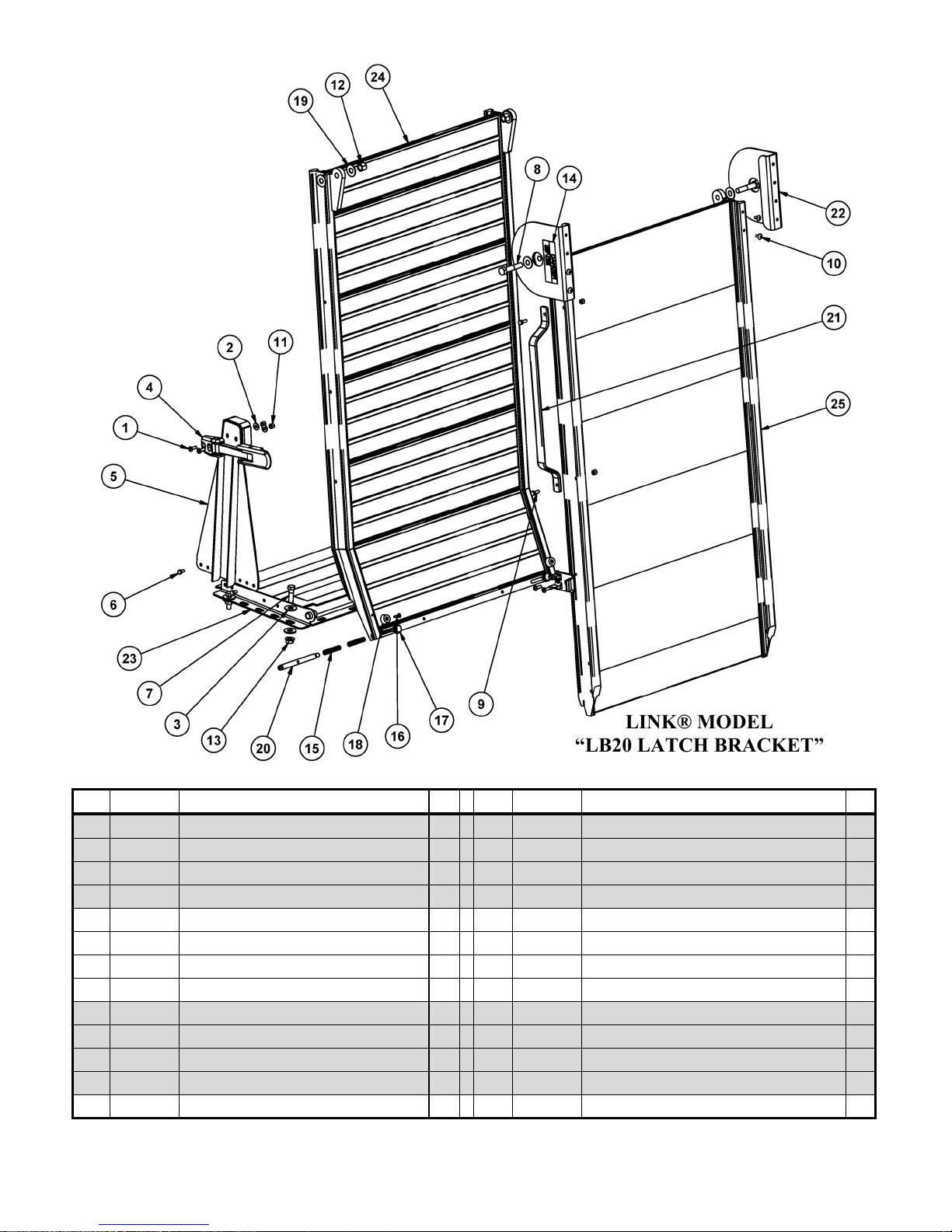
6
LINK® MODEL
“LB20 LATCH BRACKET”
PARTS LIST
** CONTACT CUSTOMER SERVICE FOR CORRECT PART NUMBER FOR YOUR RAMP
ITEM PART # DESCRIPTION QTY ITEM PART # DESCRIPTION QTY
1 14420806 1/4 X 3/4 UNC PAN HD PH MACH SCR, ZINC 4 14 1500-1311 DECAL-PINCH POINT 2
2 14870800 1/4 TYPE A PLAIN WASHER 2 15 1501-0001 COMPRESSION SPRING 4
3 14871400 7/16 TYPE A PLAIN WASHER 8 16 1506-0041 #10 X 3/4 SS FLAT HD TYPE B TAP SCR 2
4 15000912 AEROLATCH-LEVER ASSISTED 1 17 1507-0209 PLASTIC FLUTED KNOB, 1/4-20 X 9/16 2
5 78512000 PLATE-BUMPER 1 18 1507-0403 RUBBER-BUMPER, 1.00 O.D. X .28 2
6 1401-0804 1/4 X 1/2 UNC HEX CAP SCR (GR 5) 2 19 1508-0112 WASHER-PLASTIC, .53 ID X 1.25 OD X.063 THK 6
7 1401-1412 7/16 X 1 1/2 UNC HEX CAP SCR (GR 5) 4 20 7000-0034 BOLT-HINGE ARM 2
8 1401-1620 1/2 X 2 1/2 UNC HEX CAP SCR (GR 5) 2 21 7850-0004 HANDLE-LB10 1
9 1409-0806 1/4 X 3/4 UNC HEX CAP SCR, SS 2 22 7850-3005 GUARD-PINCH POINT 2
10 144C-0804 1/4 X 1/2 UNC TRUSS HD PH MACH SCR, SS 4 23 ** PLATE - MOUNT, REAR 1
11 1478-0800 1/4 UNC HEX NYLOCK NUT (GR B) 5 24 ** DECK-UPPER 1
12 1478-1600 1/2 UNC HEX NYLOCK NUT (GR B) 2 25 ** DECK-LOWER 1
13 1480-1400 7/16 UNC SERRATED FLANGE NUT 4
Page 7
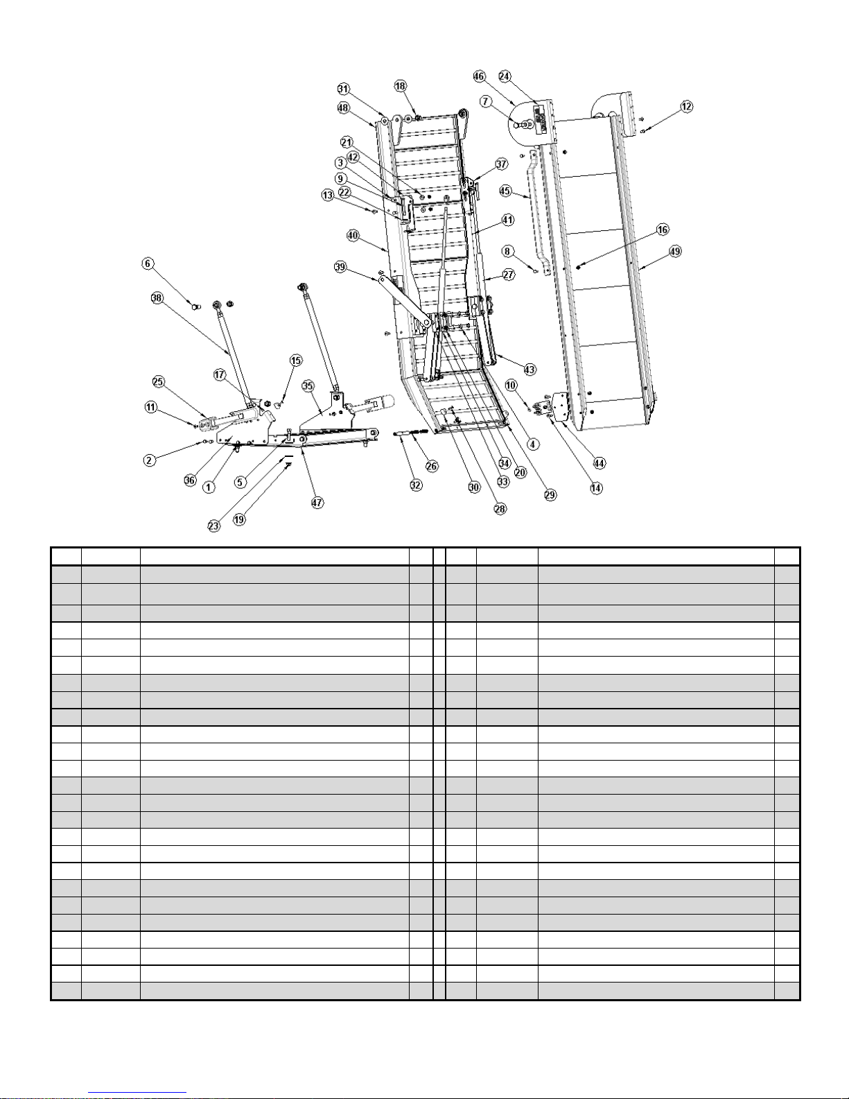
7
** CONTACT CUSTOMER SERVICE FOR CORRECT PART NUMBER FOR YOUR RAMP
ITEM PART # DESCRIPTION QTY ITEM PART # DESCRIPTION QTY
1 14010804 1/4 X 1/2 UNC HEX CAP SCR (GR 5) 4 26 1501-0001 COMPRESSION SPRING 4
2 14010806 1/4 X 3/4 UNC HEX CAP SCR (GR 5) 4 27 ** ASSEMBLY- GAS SPRING 2
3 14010808 1/4 X 1 UNC HEX CAP SCR (GR 5) 4 28 1506-0041 #10 X 3/4 SS FLAT HD TYPE B TAP SCR 2
4 14011216 3/8 X 2 UNC HEX CAP SCR (GR 5) 8 29 1507-0209 PLASTIC FLUTED KNOB, 1/4-20 X 9/16 2
5 14011412 7/16 X 1 1/2 UNC HEX CAP SCR (GR 5) 4 30 1507-0403 RUBBER-BUMPER, 1.00 O.D. X .28 4
6 14011614 1/2 X 1 3/4 UNC HEX CAP SCR (GR 5) 4 31 1508-0112 WASHER-PLASTIC, .53 ID X 1.25 OD X.063 THK 6
7 14011620 1/2 X 2 1/2 UNC HEX CAP SCR (GR 5) 2 32 7000-0034 BOLT-HINGE ARM 2
8 14090806 1/4 X 3/4 UNC HEX CAP SCR, SS 2 33 78420015 BEARING - HALF 8
9 141C1020 5/16 X 2 1/2 UNC HEX FULL THREAD CAP SCR (GR 5) 2 34 78420016 CAP - BEARING 4
10 14420803 1/4 X 3/8 UNC PAN HD PH MACH SCR, ZINC 4 35 78420030 MOUNT PLATE-LATCH, RIGHT HAND 1
11 14420806 1/4 X 3/4 UNC PAN HD PH MACH SCR, ZINC 4 36 78420031 MOUNT PLATE-LATCH, LEFT HAND 1
12 144C0804 1/4 X 1/2 UNC TRUSS HD PH MACH SCR, SS 4 37 78425103 PLATE-SPRING, ADJUSTER 1
13 144C0808 1/4 X 1 UNC TRUSS HD PH MACH SCR, SS 6 38 78425104 ASSEMBLY-TIE ROD 2
14 144C0810 1/4 X 1 1/4 UNC TRUSS HD PH MACH SCR, SS 4 39 78425105 ARM - TORQUE, LEFT 1
15 144G0P06 10-24 X 3/4 OVAL HD MACH SCR-SS 2 40 ** WELDMENT-SPRING MOUNT, LEFT 1
16 14780800 1/4 UNC HEX NYLOCK NUT (GR B) 24 41 ** WELDMENT-SPRING MOUNT, RIGHT 1
17 14780B00 10-24 UNC HEX NYLOCK NUT (GR B) 2 42 78425108 PLATE-SPRING, ADJUSTER 1
18 14781600 1/2 UNC HEX NYLOCK NUT (GR B) 6 43 78425109 ARM - TORQUE, RIGHT 1
19 14801400 7/16 UNC SERRATED FLANGE NUT 4 44 78425120 PLATE-MOUNT, STOWAGE LATCH 2
20 14851200 3/8 LOCK WASHER 8 45 7850-0004 HANDLE-LB10 1
21 14870800 1/4 TYPE A PLAIN WASHER 4 46 7850-3005 GUARD-PINCH POINT 2
22 14871000 5/16 TYPE A PLAIN WASHER 2 47 ** PLATE - MOUNT, REAR 1
23 14871400 7/16 TYPE A PLAIN WASHER 8 48 ** DECK-UPPER 1
24 1500-1311 DECAL-PINCH POINT 4 49 ** DECK-LOWER 1
25 15000912 AEROLATCH-LEVER ASSISTED 2
LINK® MODEL
“LB20 LIFT ASSIST”
PARTS LIST
Page 8
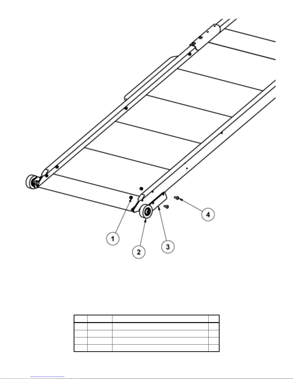
8
LINK® MODEL
“LB20 WHEEL KIT”
PARTS LIST
ITEM PART # DESCRIPTION QTY
1 14780800 1/4 UNC HEX NYLOCK NUT (GR B) 4
2 15070478 ROLLER-IDLER,ASSEMBLY 2
3 78425111 MOUNT, SUPPORT WHEEL 2
4 144C-0806 1/4 X 3/4 UNC TRUSS HD PH MACH SCR, SS 4
Page 9

9
Link Mfg. Ltd.
223 15th St. N.E.
Sioux Center, IA USA
51250-2120
 Loading...