

Page 1
Images are for illustration only and may differ from components supplied
Link Research Ltd Watford UK www.linkres.co.uk
CL140023 Issue 03
Quick Start Guide L2150 Support + (44) 1923 474099
Page 1 of 4
L2150 Quick Start Guide
Please Note:
- Do not apply power/phantom power to the audio outputs as they will be
damaged. This is an unacceptable way to operate the unit.
- Maintain the level of -20dB max on the inputs. High gain signals can cause
problems.
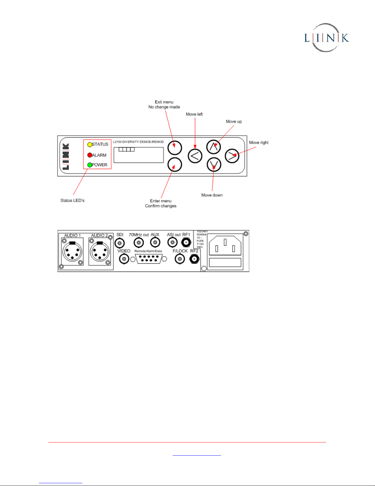
1. Front panel layout
2. Rear panel layout
Can also be configured with a DC input on a 4 pin XLR socket.
3. Uses for the L2150
The L2150 is used in 4 ways:
• As a stand alone receiver
• As an ASI multiplexer
• As a 70MHz input decoder
• As a driver for a Triax system
4. To use as a stand alone receiver
Connect:
• Two antenna inputs from the down convertors to RF1 and RF2.
• Black and burst (or other local reference) to F/LOCK
• Audio connectors to AUDIO 1 and AUDIO 2
• Output connector to SDI or ASI as required
• Local monitoring to VIDEO
Note 1 ~ early units may
have the audio output
connected via a tag
strip.
Note 2 ~ AUX is the ASI
input for multiplexing
Page 2

Images are for illustration only and may differ from components supplied
Link Research Ltd Watford UK www.linkres.co.uk
CL140023 Issue 03
Quick Start Guide L2150 Support + (44) 1923 474099
Page 2 of 4
Menu set ups:
Use the enter menu key to enter the menu structure. Press the Move Down Button to get to the
sub menu heading.
• Unit menu - in Mode select Diversity and press the enter key.
In Dconv Type select appropriate type and press the enter key.
In LNB Power select Yes and pres the enter key. The down convertor LED’s should come on
and the first two boxes on the top left of the LCD display should have 9 showing in them.
In Format select the required output format (ASI, DVB-T or DVB-S). Note SDI and
baseband video are only output if DVB-S is selected.
• Input Frequency – Go to OFDM 1 sub menu and select Input Frequency. Use the
left/right/up/down keys to set the correct frequency. Press Enter to confirm.
If a Link Research down convertor is being used check in the D Conv LO sub menu that
1.84GHz is displayed. If using a non Link Research unit, set the local oscillator to the
Manufacturer’s recommended frequency and press Enter to confirm.
If there is a transmitter operating on the input frequency and within range, the Yellow
Status LED should be on showing the receiver is locked to the incoming signal and the
Status menu will show the input signal strength. If it is not locked, check the menu
settings above again resetting as needed.
• In Decoder menu, go to Service Name and check the service name is the same as that set
on the transmitter. Press Enter to confirm.
Go to Default Service and set the default service name to the same as the transmitter
Service Name. Press Enter to confirm.
• If ASI is the output format, go to the Multiplexer menu. In the ASI OP sub menu set the
packet size as required. In the Bitrate sub menu set the bitrate to a suitable figure. In the
Network sub menu set the network name as required.
The system should now be working correctly.
Errors and warnings
• Down convertor LED’s should be
orange. If they are red, an error condition exists. Switch
off the receiver or remove the coax cable and then switch on or replace the cable. The
LED should be orange. If the receiver has been power cycled, remember to go to the Unit
menu and turn the LNB Power to Yes.
• Alarm LED is lit and DEC is flashing on the LCD. No service has been selected or no service
can be detected. Go to the Decoder menu and use the Service Name sub menu to select
the service name.
• Check that the transmitter is transmitting. The green RF LED must be lit.
• If OVF is flashing on the LCD, the input buffers are overflowing. Reboot the receiver. If
the error message still persist go to the Memory menu and select Default Restore, Yes and
then re-enter the set up as described above.
5. To use as an ASI multiplexer
Note – Any Link Research receiver can be used in this mode.
Connect:
• The cables as for a stand alone receiver
• An ASI input to the AUX connector
Menu set ups:
Use the enter menu key to enter the menu structure. Press the down arrow to get to the sub menu
heading.
• Go to ASI Input 3 menu and check that the incoming signal is locked. If it is not check that
it is being correctly formatted at source.
• Go to the Multiplexer menu and in the Bitrate sub menu, set the bit rate to an appropriate
figure.
Page 3

Images are for illustration only and may differ from components supplied
Link Research Ltd Watford UK www.linkres.co.uk
CL140023 Issue 03
Quick Start Guide L2150 Support + (44) 1923 474099
Page 3 of 4
6. To use as a 70MHz IRD (at a Triax base station)
Connect:
• 70MHz modulated input to RF1 (from L1271 base station)
• Black and burst (or other local reference) to F/LOCK
• Audio connectors to AUDIO 1 and AUDIO 2
• Output connector to SDI or ASI as required
• Local monitoring to VIDEO
Menu set ups:
Use the enter menu key to enter the menu structure. Press the down arrow to get to the sub menu
heading.
• Unit menu - in Mode select Single and press the enter key.
In Dconv Type select None and press the enter key.
In LNB Power select No and pres the enter key.
In Format select DVB-S or DVB-T as appropriate.
If there is a valid signal on the input, the Yellow Status LED should be on showing the receiver is
locked to the incoming signal. If it is not locked, check the menu settings above again resetting as
needed. Also check that sufficient power is being used to launch the signal on the cable.
• In Decoder menu, go to Service Name and check the service name is the same as that set
on the transmitter. Press Enter to confirm.
Go to Default Service and set the default service name to the same as the transmitter
Service Name. Press Enter to confirm.
7. To use as a Triax driver (at Triax remote station)
The L2150 can be used to drive up to 3 services down a Triax cable. For a single service, set the
receiver up as described in stand-alone receiver above.
Additional connections:
• Connect the modulated 70MHz output to the input of the L1272
• Connect DC power from the L1272 to the L2150 (must be DC input version)
Menu set ups:
•
In Unit menu Format select DVB-T. Note ~ local monitoring is not available
• In Modulator menu go to Guard Int and select 1/32
• In Modulator menu go to FEC and select ¾, 5/6 or 7/8
• In Modulator menu go to Polarity and select Norm
• If in DVB-T mode in Modulator menu go to Width and select 8MHz
• In Modulator menu go to Level and adjust output power. Note the level is adjustable in
1dBm steps from -6dBm to -12dBm. Use lower power for shorter cable, higher power for
longer or poor quality cable. Max Triax cable length 1½km.
• In Modulator menu go to Freq and set the output frequency. Note the frequency range is
adjustable between 65MHz and 75MHz.
• In Modulator menu go to Output and set to On.
The receiver at the Triax base station (L2102 or L2104) will need to be configured with parameters
that match those set on the L2150. The output from the Triax base station is connected to RF1 and
the receiver set to Single in the Mode sub menu of the
Unit menu.
Page 4
Images are for illustration only and may differ from components supplied
Link Research Ltd Watford UK www.linkres.co.uk
CL140023 Issue 03
Quick Start Guide L2150 Support + (44) 1923 474099
Page 4 of 4
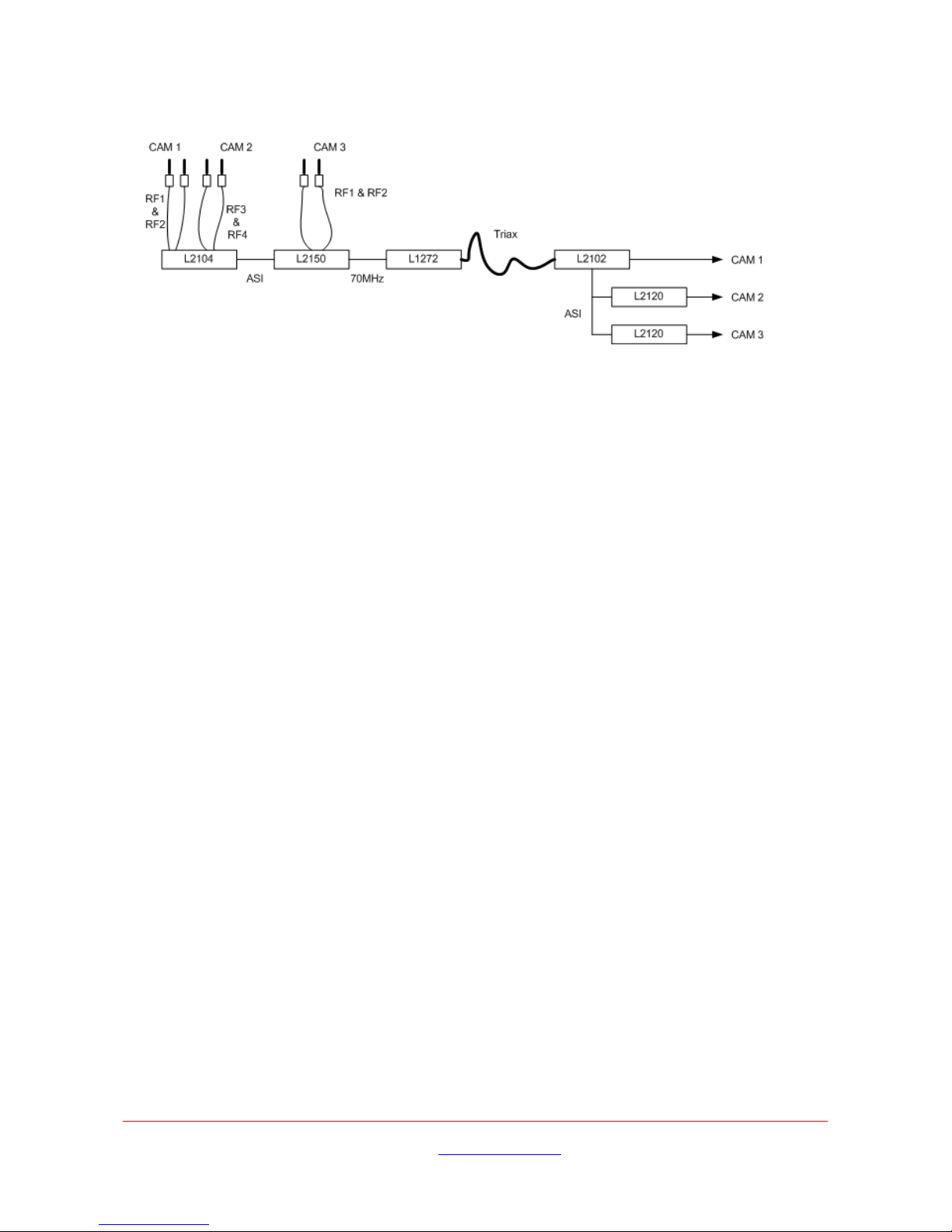
8. To use as a two or three input Triax driver (at Triax remote station)
The system will look something like the diagram below:
Connect:
• As shown in the diagram.
Menu set ups:
L2104
• In Unit menu Mode set to Remux
• In Unit menu set LNB Power to On
• In OFDM1 & OFDM2 set the input frequency for PGM1
• In OFDM3 & OFDM4 set the input frequency for PGM3
L2150
• In Unit menu Format select DVB-T.
• In Modulator menu go to Mod Mode and select 64-QAM.
• In Modulator menu go to Guard Int and select 1/32.
• In Modulator menu go to FEC and select ¾, 5/6 or 7/8.
• In Modulator menu go to Polarity and select Norm.
•
If in DVB-T mode in Modulator menu go to Width and select 8MHz.
• If in DVB-S mode in Modulator menu go to Sym and set the symbol rate.
• In Modulator menu go to Level and adjust output power. Note the level is adjustable in
1dBm steps from -6dBm to -12dBm. Use lower power for shorter cable, higher power for
longer or poor quality cable. Max Triax cable length 1½km.
• In Modulator menu go to Freq and set the output frequency. Note the frequency range is
adjustable between 65MHz and 75MHz.
• In Modulator menu go to Output and set to On.
Transmitters
• Using Link Control, Auto set Service Name set each transmitter’s service name and PID
numbering so there is no clash between the services.
• Using Link Control, Modulator set the frequencies for CAM 1, CAM 2 and CAM 3.
• Using Link Control, Modulator set OFDM mode to QPSK.
L2102
• In Unit menu set LNB Power to Off.
• In Unit
menu set Mode to Single.
• In Unit menu set Dconv Type to None.
• In OFDM1 menu set the input frequency to the same as the L2150 output.
• In Decoder menu set Service Name to that of CAM 1.
L2120
• In Decoder menu set Service Name to that of CAM 2 (first decoder) and CAM 3 (second
decoder).
 Loading...