

Link L1360 Instruction Manual

LINK RESEARCH PRODUCT MANUAL
L1360 XPc Transmitter Manual
Contact: Link Research Main +44 (0) 1923 474 060
Support +44 (0) 1923 474 099
Web: www.linkres.co.uk
Link XPc
Compact Encoder/Modulator Manual
1 Introduction 3
2 Product Description 3
3 Product Operation 4
3.1 Serial port interface 4
3.2 LEDs 4
3.3 Basic operation 4
3.4 Default Settings 5
3.5 Specification 6
3.6 Connector Interface 7
3.7 Mechanical 8
4 Configuration & Firmware Upgrades 9
4.1 XPc Configuration via Link Control 9
4.2 Firmware Upgrades 10
5 XPc Product Part Numbers 13
6 Part Numbers for XPc Accessories 13
Link Research Ltd www.linkres.co.uk
Images are for illustration only and may differ from components supplied
Page 1 of 14 CL140067 Issue B Link XPc Manual
Support UK/Europe + (44) 1923 474099 USA +(1)9786715700

Document Link XPc Encoder/Modulator Manual
Safety and Compliance
Any mains power equipment must be earthed. Operate the equipment within environmental limits and
ensure as much ventilation as possible (Normally Temp 0C-50C <99% humidity). Only authorised
personnel should open the product and any repair or warranty will be invalidated if the unit is
opened.
The equipment has been designed to be CE compliant and an EC Declaration of Conformity and
Technical files are available on request.
Please contact Link SUPPORT any issues.
Please ensure that normal anti-static precautions are taken when removing the XPc interface
connector from the main unit.
Operators are advised to always check that their application complies with the requirements of the
relevant frequency authority. Frequency allocations vary from time to time. Most require individual
licences for operation. All known restrictions are indicated in the notes below. Contact details for EU
authorities can be found at http://ec.europa.eu/enterprise/rtte/spectr.htm
This product is not approved for permanent mounting in commercial vehicles.
Issue Date Comments
A June 2009 Working draft
B June 2009 Typo’s & minor changes
.
Link Research Ltd www.linkres.co.uk
Images are for illustration only and may differ from components supplied
Page 2 of 14 CL140067 Issue B Link XPc Manual
Support UK/Europe + (44) 1923 474099 USA +(1)9786715700

1 Introduction
The Link XPC compact Encoder/Modulator is a highly integrated product, which can be employed in a
number of different scenarios. It includes an SD MPEG2 encoder and also supports a range of
modulators ; DVB-T and LMS-T. LMS-T is Link Research’s proprietary modulation scheme, which
offers higher bitrate and robustness in many applications.
This manual describes operation of the XPC only. For details of the receiving end please see the
relevant manual.
This manual assumes a reasonable knowledge of broadcast systems. It is intended to be used as a
basic reference; full support with integration of the product will be provided directly by Link Research
Ltd.
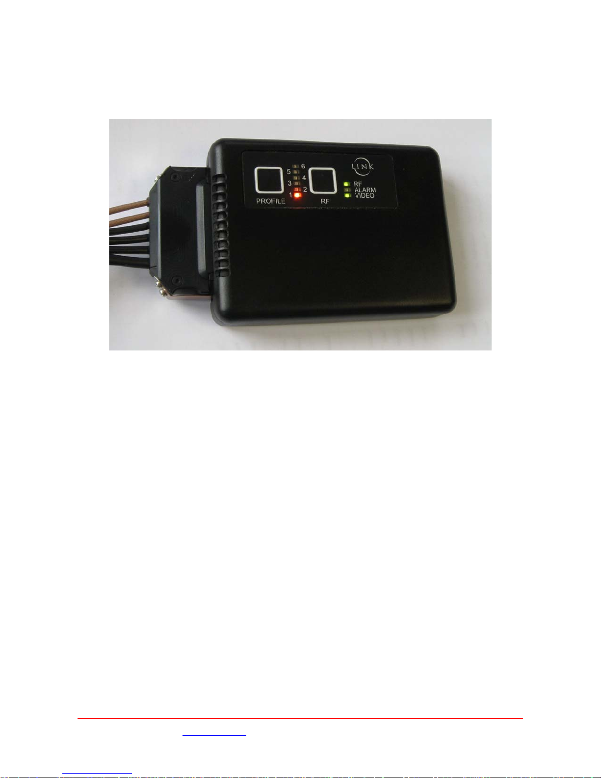
2 Product Description
Control Buttons
Interface
connector
Cooling slots
The XPC is intended to be mounted using the four mounting holes (for mechanical details see section
3.7.1).
The cooling fan allows the unit to operate in ambient temperatures of at least 50˚C. Ensure that there
is sufficient clearance around the unit to allow free airflow into and from the cooling slots. Operation in
higher temperature environments may be possible depending on what external cooling is available –
consult Link Research Ltd. if this is required. It should not be mounted on a hot surface.
The XPc provides two RF outputs (with phantom power) designed to drive a range of amplifiers and
active antennas. Please contact Link Research Ltd. for the full range of options.
Status LEDs
Link Research Ltd www.linkres.co.uk
Page 3 of 14 CL140067 Issue B Link XPc Manual
Images are for illustration only and may differ from components supplied
Support UK/Europe + (44) 1923 474099 USA +(1)9786715700
3 Product Operation
The XPC has a simple control panel that allows the selection of pre defined Profiles and the control of
the RF output. LEDs provide an indication of the unit’s status; the current Profile and state of the RF
output and unit Alarms. The Profiles are edited in the XPc using Link Control software running on a PC.
See section 4.1 for details.
3.1 Serial port interface
The XPC has an RS232 port which can be used to communicate with a PC or similar. The protocol for
this communication is described in a separate document, which is available on request from Link
Research Ltd. Link Control
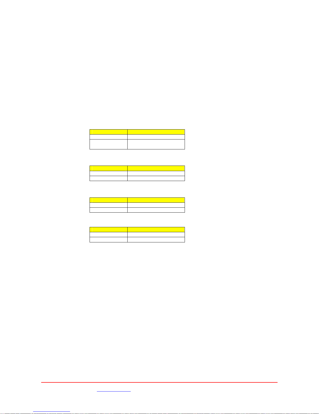
3.2 LEDs
Profile:
Colour Function
Off No power present
Orange 1-6 Indicates the current
selected Profile
RF :
Colour Function
Off RF Off
Green RF outputs On
Alarm:
Colour Function
Off Operational
Red Alarm condition
Video :
Colour Function
Off Video not locked
Green Video locked
3.3 Basic operation
As an example of how to get started with the XPc
1. Connect the required RF power amp(s) to the RF output of the harness.
2. Connect the required video and audio (if required) inputs using the appropriate multipin
harness.
3. Apply power to the XPc. Confirm that one of the Profile LED turns orange, this indicates the
last used Profile.
4. Select the required operating Profile using the Profile button.
5. Turn on the RF outputs using the RF button.
Images are for illustration only and may differ from components supplied
Link Research Ltd www.linkres.co.uk
Page 4 of 14 CL140067 Issue B Link XPc Manual
Support UK/Europe + (44) 1923 474099 USA +(1)9786715700
 Loading...