

Page 1

L1125 User Guide
L1125 Camera Control System
L1125 shown with a LinkXP Transmitter (sold separately)
Images are for illustration only and may differ from components supplied
Link Research Ltd, 23 Watford Metro Centre, Dwight Road, Watford, Herts, WD18 9XA, UK
Telephone +44 1923 200900 (general), +44 1923 200909 (Customer Support)
© Link Research Limited 2004, 2005 Page 1 of 25
Page 2
L1125 User Guide
L1125 System Components:
1) 1 x L1125 Reverse Control Camera Back
2) 1 x L3421 1.95-2.7GHz Flexible antenna
3) 1 x Rain Guard
4) 1 x Latch Plate (fixes to LinkXP Transmitter)
5) 1 x L3040 Transmit Filter
6) 1x L1303 XPe Transmitter
7) 1x L3522 XPe TX Antenna
8) 1 x Link XPRV Cable Pack
9) 1x L1251 OCP Interface
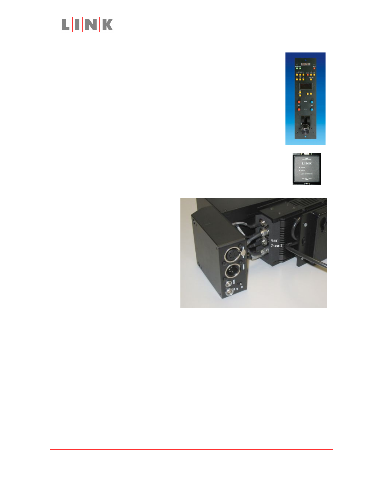
Connecting the LinkXP transmitter to the L1125
Flying leads in the L1125 connector
box plug into the connectors on the
base of the LinkXP transmitter. The
connections are labelled according
to the connector they plug into, i.e.
Connection XP connector
XP Power -> DC IN
XP RS323 -> RS232
XP AUDIO 1 -> AUDIO 1
XP AUDIO 2 -> AUDIO 2
XP VIDEO Y -> Y/VID/SDI
XP VIDEO U -> U
XP VIDEO V -> V
If using a composite video connection from the camera instead of the component
connections, connect XP VIDEO COMP to the Y/VID/SDI connector. Otherwise this
connections is fitted to the back of the BNC jack on the connector box.
The foam rain guard shields the connectors.
Images are for illustration only and may differ from components supplied
Link Research Ltd, 23 Watford Metro Centre, Dwight Road, Watford, Herts, WD18 9XA, UK
Telephone +44 1923 200900 (general), +44 1923 200909 (Customer Support)
© Link Research Limited 2004, 2005 Page 2 of 25
Page 3
L1125 User Guide
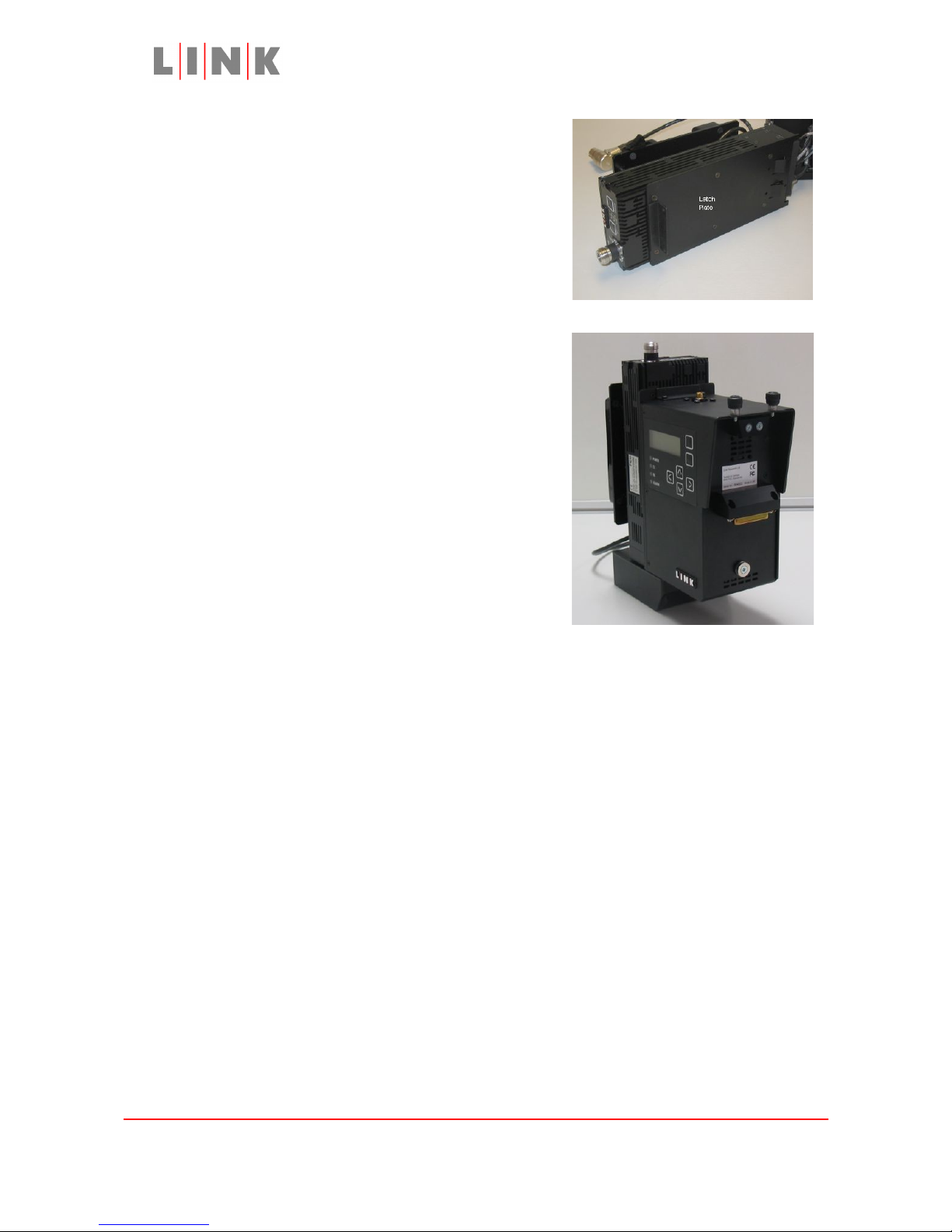
A latch plate is fixed to the LinkXP transmitter to
allow it to be mounted on the L1125 Camera Back.
The tongues on the lower part of the latch plate
slide into slots in the rear panel of the camera back,
the transmitter is then fixed in place with two
screws through the top bracket on the latch plate.
Connecting the L1125 to the
camera
The L1125 Camera Back has a standard BVV-5
camera interface, it is secured to the camera by
two thumbscrews. The video, power and (in some
cases) control signals for the camera pass through
the BVV-5 connector.
Some cameras (e.g. Philips LDK 100/200, Sony 950)
do not provide access to their control link via the
BVV-5 interface and require an external control
cable (e.g. L0016 or L0017). The control cable goes
from the L1125 “EXT” connector to the camera’s
external control connector.
Connecting the battery
The Lemo lead from the battery mounting plate plugs into the power connector on
the rear of the L1125.
The battery mount has a rocker switch on top, this switch controls power to the
LEMO connector to allow the entire system and camera head to be powered on or
off.
Images are for illustration only and may differ from components supplied
Link Research Ltd, 23 Watford Metro Centre, Dwight Road, Watford, Herts, WD18 9XA, UK
Telephone +44 1923 200900 (general), +44 1923 200909 (Customer Support)
© Link Research Limited 2004, 2005 Page 3 of 25
Page 4
L1125 User Guide
Configuring the L1125 and the LinkXP transmitter
via the L1125 menu system
Exit
Button
Display Area
Enter
Button
LED
Navigation
Status
Keys
Indicators
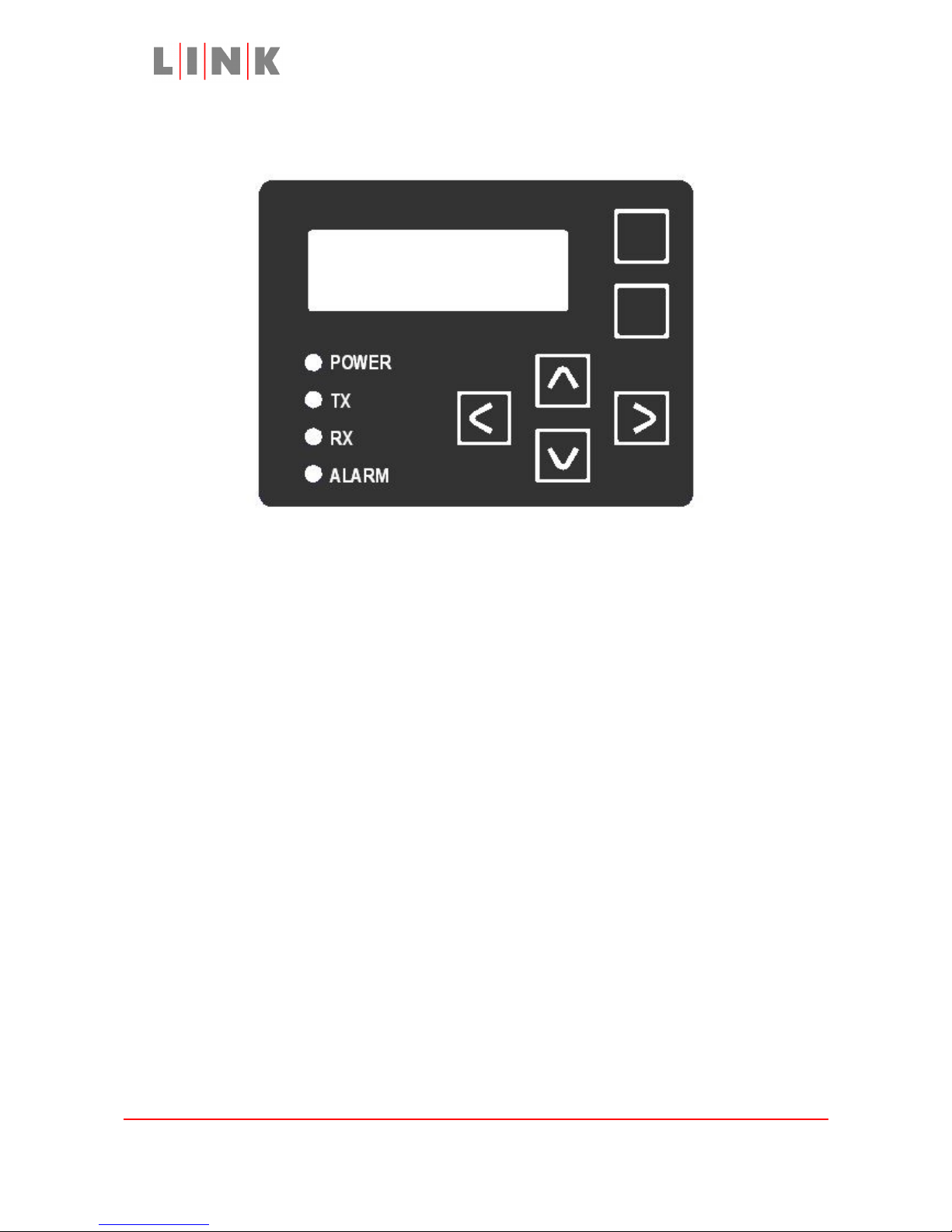
The control panel on the side of the L1125 allows the camera back and the LinkXP
transmitter to be configured.
Control Panel Status Indicator Meanings
The POWER LED is green whenever power is applied unless status LED
illumination has been turned off in the menu.
The TX LED reflects the status of the LinkXP RF LED, on when the transmitter is
active.
The RX LED flashes when a command has been received and successfully
transferred to the camera (This may be continuously illuminated).
The ALARM LED is red whenever there is an alarm condition, the source of the
alarm will be shown on the bottom of the display, possible alarm sources are:
CTL Camera control disabled, this is displayed if control has been turned
off in the menu or, if so configured, control has been disabled
automatically because the data link has been inactive more than 12
seconds.
VID Video Alarm, shown if LinkXP is not locked to a valid video source
FWD Forward Path alarm, RS232 communications to LinkXP has been lost
(e.g. RS232 cable disconnected or LinkXP set to IR mode)
Images are for illustration only and may differ from components supplied
Link Research Ltd, 23 Watford Metro Centre, Dwight Road, Watford, Herts, WD18 9XA, UK
Telephone +44 1923 200900 (general), +44 1923 200909 (Customer Support)
© Link Research Limited 2004, 2005 Page 4 of 25
Page 5
L1125 User Guide
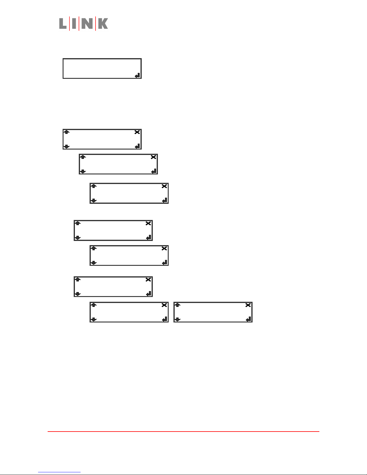
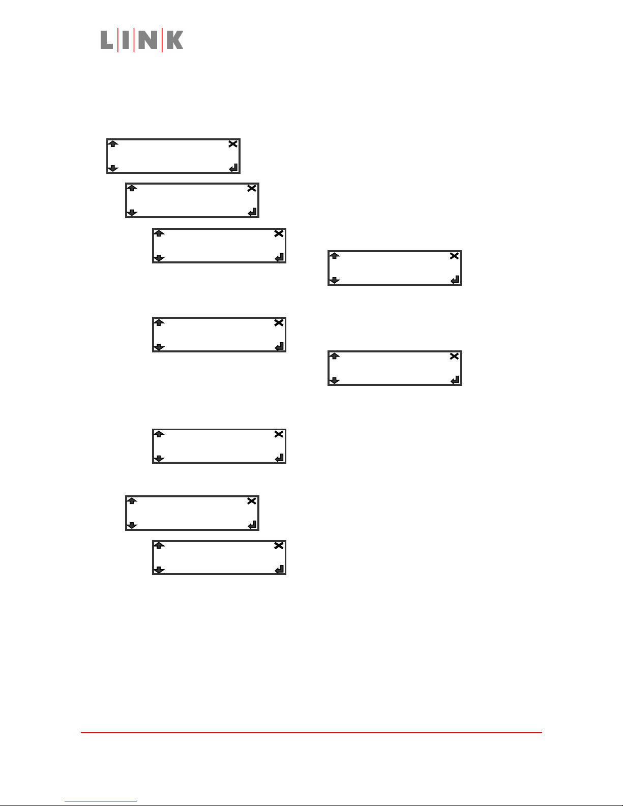
L1125 Menus
Initial Display after power-up
Press the Enter button for menus
The Memory Menu
The entries in the Memory menu are used to load and store profiles or to reset all settings
to their default values.
Press the Enter button to go into the Memory menu
Press the Enter button at this point to select a
profile in which to save the current settings of all
menu entries
Use the up/down buttons to choose a profile
then press the Enter button to store, or press
the Exit button to quit without storing the
settings.
Press the Enter button at this point to select a profile
from which to retrieve settings for all menu entries
Use the up/down buttons to choose a profile
then press the Enter button to load, or press the
Exit button to quit without loading the settings
Press the Enter button then use the up/down buttons
to choose Yes, then press Enter again to reset all
settings to their default values.
Note 1: The PROFILE button on the LinkXP transmitter can also
be used to load the settings for the profile it selects.
Note 2: If the L1125 is powered off it will power up with the
settings last saved to the profile that was in use,
setting changes MUST be saved to a profile to preserve
them after power cycle.
Images are for illustration only and may differ from components supplied
Link Research Ltd, 23 Watford Metro Centre, Dwight Road, Watford, Herts, WD18 9XA, UK
Telephone +44 1923 200900 (general), +44 1923 200909 (Customer Support)
© Link Research Limited 2004, 2005 Page 5 of 25
Link XPR L1125
Memory…
Store Profile…
Restore Defaults…
-> 1
-> 1
-> No -> Yes
Load Profile…
Page 6
L1125 User Guide
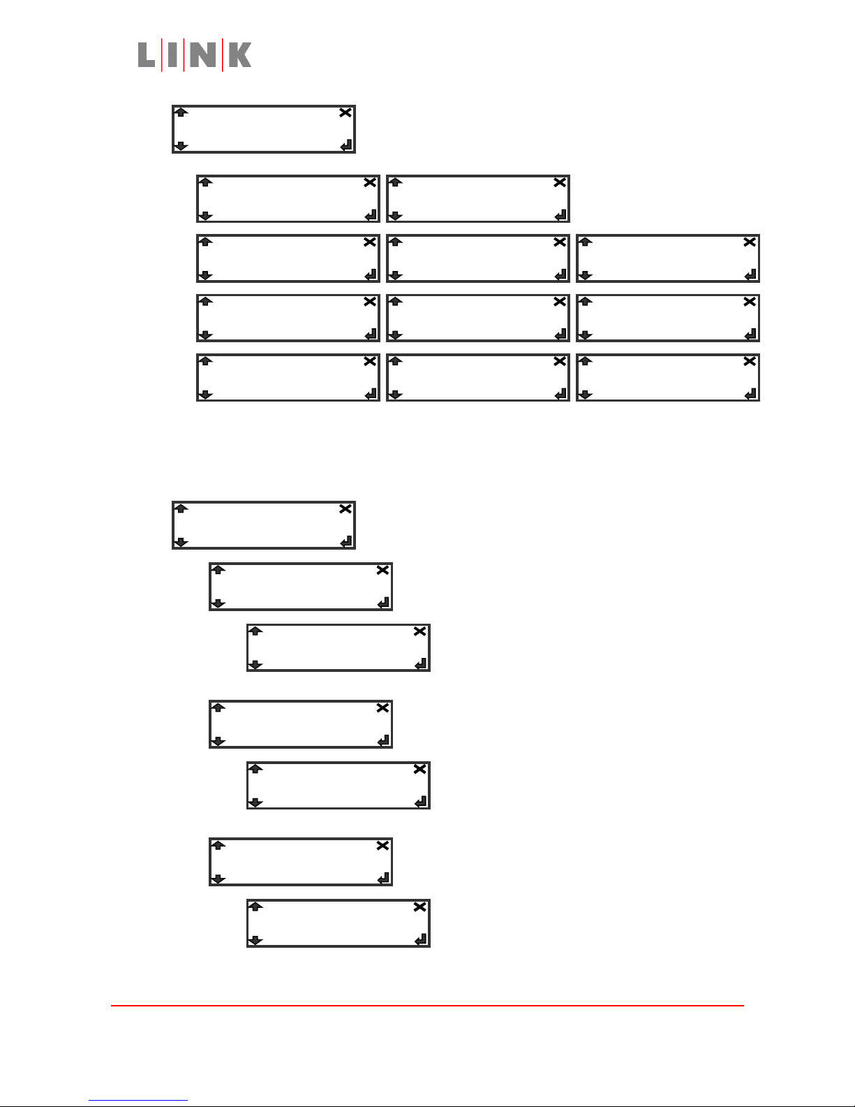
The Forward Path Menu
The entries in the Forward Path menu are used to configure the settings of the LinkXP
transmitter.
Press the Enter button to go into the Forward Path menu
Press Enter then use the up/down buttons to select
the required modulation scheme
Press Enter
then use
the
up/down buttons to select the required transmit power, press Enter to apply the setting
Press the
Enter
button to
edit the frequency
Use the left/right buttons to select digits in the
frequency and the up/down buttons to change
them, press Enter to apply the new frequency
Press Enter then use the up/down buttons to select
the Forward Error Correction ratio
Images are for illustration only and may differ from components supplied
Link Research Ltd, 23 Watford Metro Centre, Dwight Road, Watford, Herts, WD18 9XA, UK
Telephone +44 1923 200900 (general), +44 1923 200909 (Customer Support)
© Link Research Limited 2004, 2005 Page 6 of 25
Forward Path…
Mode: QPSK
FEC: 1/2
-> 3/4
-> 002.3950 GHz
-> 100 mW
-> 50 mW
-> 10 mW
-> 5/6
-> 7/8-> 1/2-> 2/3
Freq: 2.3950 GHz
Power: 100 mW
-> 64QAM
-> 16QAM
-> QPSK
Page 7
L1125 User Guide
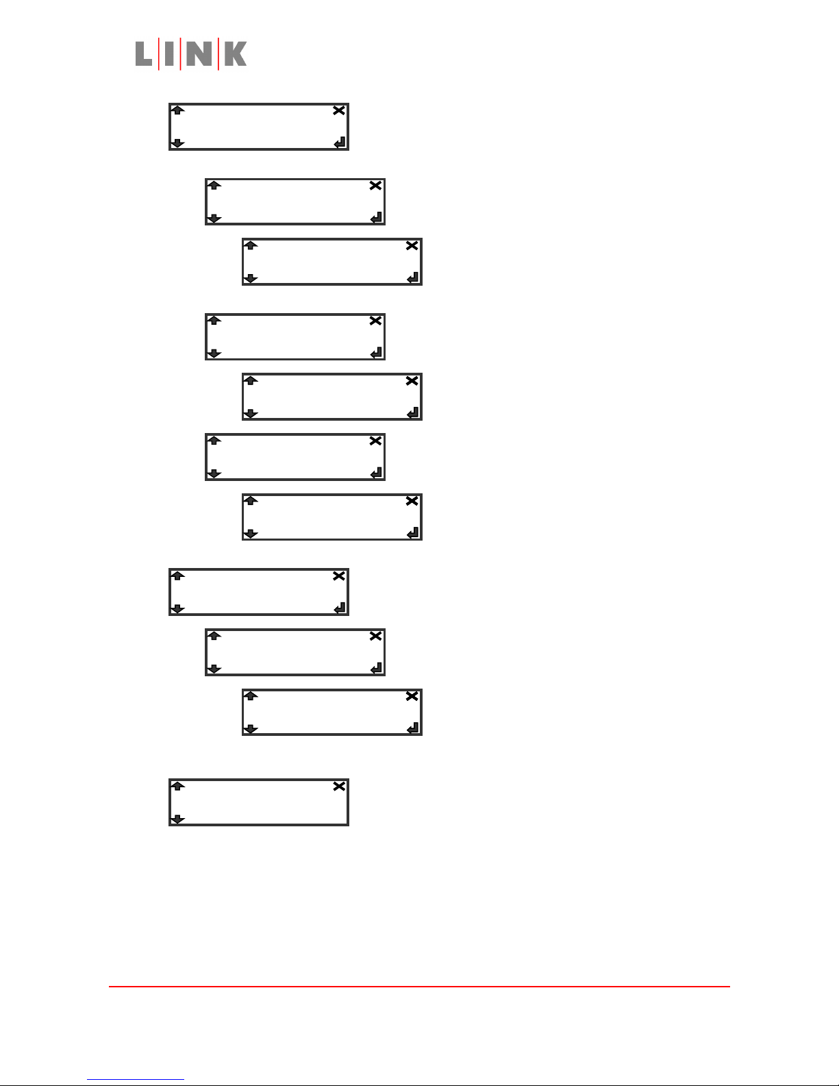
Press Enter then use the up/down buttons to select
the required video format. “NTSC No Ped” is
composite video with no pedestal (i.e. black level
0IRE instead of 7.5IRE)
Bars are generated
by LinkXP
Note 1:
The composite formats are only appropriate if the camera has been
connected to the L1125 via a composite video connection instead of
component connections
Press Enter to configure the settings for the audio
channel from the camera (one mono signal)
Press Enter then use the up/down buttons to
configure the amplifier gain
Press Enter then use the up/down buttons to
select either microphone level or line level
Press Enter then use the up/down buttons to
turn microphone phantom power (48V) on or off
Images are for illustration only and may differ from components supplied
Link Research Ltd, 23 Watford Metro Centre, Dwight Road, Watford, Herts, WD18 9XA, UK
Telephone +44 1923 200900 (general), +44 1923 200909 (Customer Support)
© Link Research Limited 2004, 2005 Page 7 of 25
Input: PAL
Camera Audio…
Mic/Line: Mic
Gain: 50 dB
-> NTSC
-> PAL-N
Mic Power: Off
-> 50 dB
-> Mic-> Line
-> Off-> On
-> YPbPr 525-> YPrPb 525 -> 525 Betacam
-> PAL
-> PAL-M
-> NTSC No Ped
-> Bars 525-> Bars 625
-> YPbPr 625
Page 8
L1125 User Guide
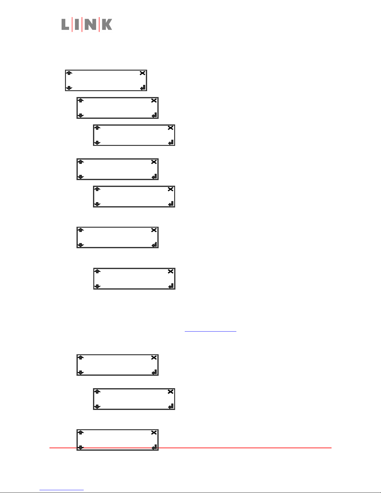
Press Enter to configure settings for the audio channel
from the L1125 Headphone/Audio XLR connector (one
mono signal)
Press Enter then use the up/down buttons to
configure the amplifier gain
Press Enter then use the up/down buttons to
select either microphone level or line level
Press Enter then use the up/down buttons to
turn microphone phantom power (48V) on or off
Press Enter to configure settings for the Audio 2
channel on the LinkXP transmitter (one stereo signal)
Press Enter then use the up/down buttons to
turn the Audio 2 channel on or off
This menu entry provides additional information for
any alarm indications shown on the bottom line of the
display
Images are for illustration only and may differ from components supplied
Link Research Ltd, 23 Watford Metro Centre, Dwight Road, Watford, Herts, WD18 9XA, UK
Telephone +44 1923 200900 (general), +44 1923 200909 (Customer Support)
© Link Research Limited 2004, 2005 Page 8 of 25
Audio 2…
Status: OK
External Audio…
Mic/Line: Mic
Gain: 50dB
Mic Power: Off
-> 50dB
-> Mic-> Line
-> Off-> On
-> Off
-> On
Audio 2: Off
Page 9
L1125 User Guide
The Reverse Path Menu
The entries in the Reverse Path menu are used to configure camera control settings.
Press enter to edit the frequency.
Use the left/right buttons to select digits in the
frequency and the up/down buttons to change
them, press Enter to apply the new frequency
Press Enter then use the up/down buttons to select
the camera address
Press Enter to apply the selection
Camera selection, current choices (as of software
V0.48):
Philips LDK100, Panasonic AWE600, Sony DXC-
D30/D35,
JVC KY-D29, Type 12, Type 13, Type 14, Type 15,
Sony BVP-70, Sony BVP-30, Ikegami Handheld,
Ikegami Studio, Sony BVP90/550, Hitachi Z3000, Ikegami (1-Way), Sony 950/BVP-E10. All
the cameras supported by L1125, including
details of any modifications and drawings for
cables, are listed under "support options" at
www.linkres.co.uk
Changes the camera control protocol (dependent on
camera type.)
Only offered if the camera supports control through
the BVV-5 or an external cable, choose the connection
method used
Images are for illustration only and may differ from components supplied
Link Research Ltd, 23 Watford Metro Centre, Dwight Road, Watford, Herts, WD18 9XA, UK
Telephone +44 1923 200900 (general), +44 1923 200909 (Customer Support)
© Link Research Limited 2004, 2005 Page 9 of 25
Reverse Path…
Freq: 2.1000 GHz
-> 002.1000 GHz
Camera Address: 1
Cam: Sony BVP-30
-> 1
-> Sony BVP-30
Control Mode: 0
-> 0-> 1
Cam I/F: Internal
Page 10

L1125 User Guide
Images are for illustration only and may differ from components supplied
Link Research Ltd, 23 Watford Metro Centre, Dwight Road, Watford, Herts, WD18 9XA, UK
Telephone +44 1923 200900 (general), +44 1923 200909 (Customer Support)
© Link Research Limited 2004, 2005 Page 10 of 25
-> Internal-> External
Page 11
L1125 User Guide
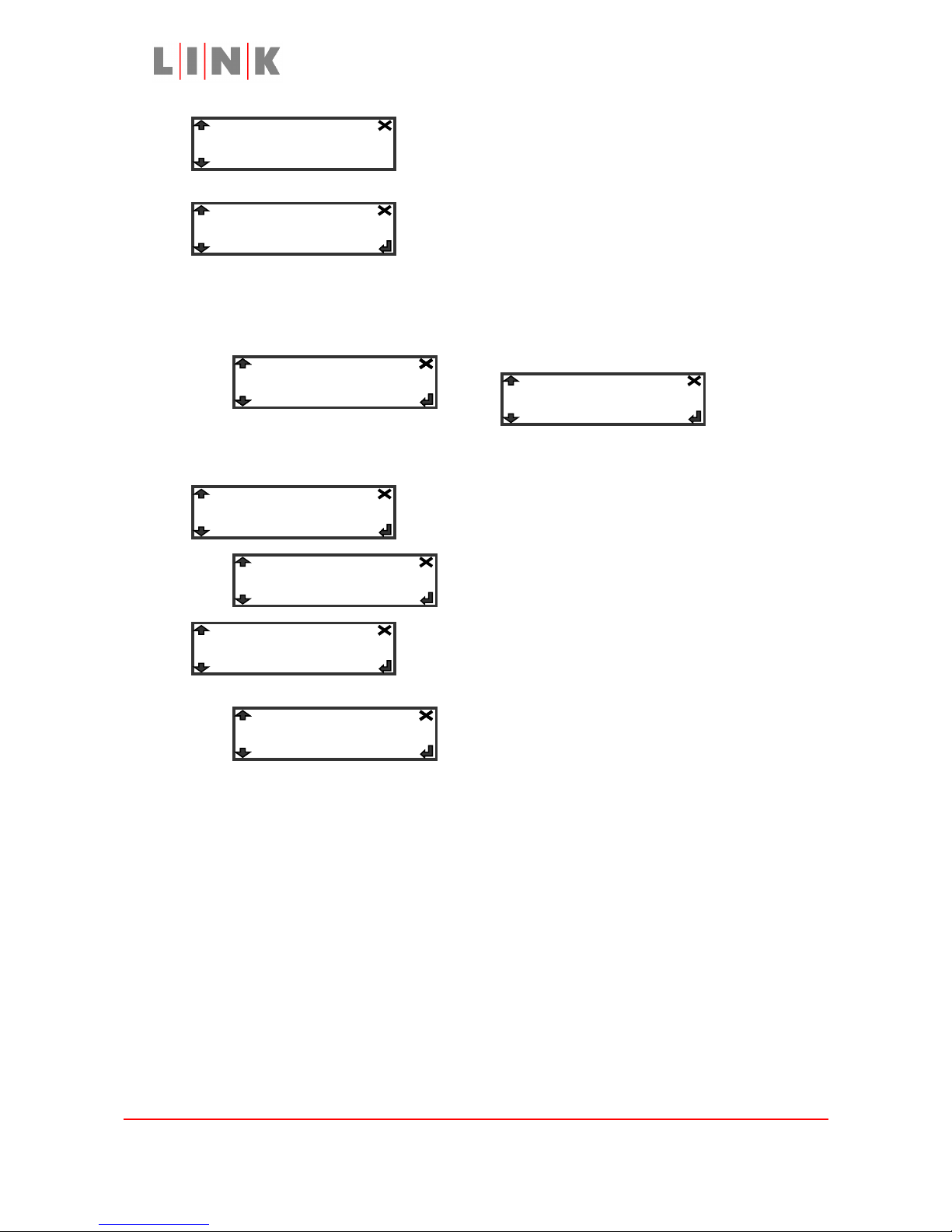
This menu entry provides additional information for
any problems with the reverse path.
This entry is used
to disable
camera control
(the Off setting,
which restores local control), to enable camera control
(the On setting) or to automatically disable control if
the reverse link is lost for > 12 seconds (the Auto
setting).
Details
core
parameters relating to the cameraback mounted receiver such as SNR, MER, Pre and Post
Viterbi figures.
This entry is used to adjust the output level of the
talkback headset.
Press Enter to apply the selection
This entry is used to change the polarity of the Ret
lens switch when controlling the external video
socket.
Images are for illustration only and may differ from components supplied
Link Research Ltd, 23 Watford Metro Centre, Dwight Road, Watford, Herts, WD18 9XA, UK
Telephone +44 1923 200900 (general), +44 1923 200909 (Customer Support)
© Link Research Limited 2004, 2005 Page 11 of 25
Camera Control:
-> Auto-> On-> Off
Status: OK
Quality…
Headphone Gain: 0
SW Polarity:
-> 1
-> Normal
-> Inverse
Page 12
L1125 User Guide
The Unit Menu
The Unit menu is used to configure settings for the L1125 camera back.
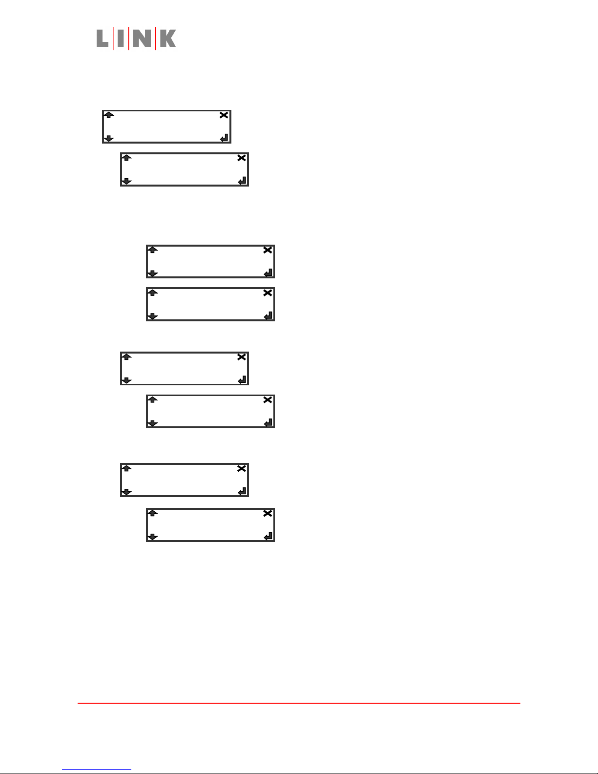
This Entry defines the function of the rear RS232
connection. Its normal use is for data to be passed to
LinkXP, but it can also be configured to allow RS232
connection to the receiver or the LinkXP control port.
N.B. If Decoder Control or XP Control are selected camera
control is lost until power to the L1125 is turned off and back
on
This Entry adjusts the LCD contrast.
Note: LCD Contrast is not saved in profiles
Press Enter to apply the selection
Setting Lock to On prevents any menu
setting changes from being applied.
Images are for illustration only and may differ from components supplied
Link Research Ltd, 23 Watford Metro Centre, Dwight Road, Watford, Herts, WD18 9XA, UK
Telephone +44 1923 200900 (general), +44 1923 200909 (Customer Support)
© Link Research Limited 2004, 2005 Page 12 of 25
Unit…
RS232: XP Data
Lock: Off
-> 5
-> Off-> On
LCD Contrast: 5
-> Cam Control
-> Decoder Control
-> XP Control
-> XP Data
Page 13
L1125 User Guide
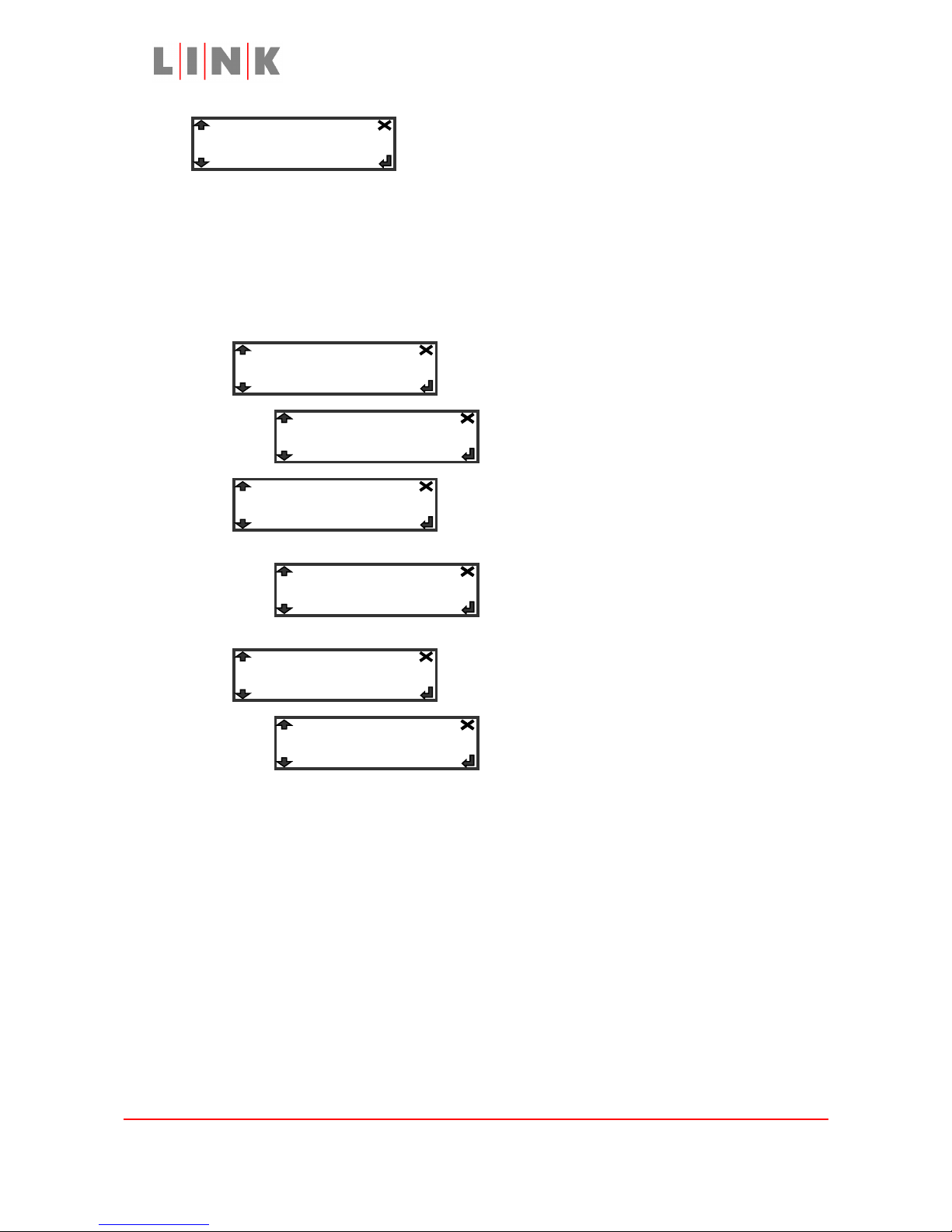
The Upgrade entry is used to configure the system for
software
upgrading via the
rear RS232
connection. Upgrades are downloaded via a terminal
package (e.g. Tera Term)
If any of the Upgrade entries are set to Reprogram
normal operation is not restored until power is
turned off and on
Set the XP entry to Reprogram then press Enter
to upgrade software in the LinkXP transmitter
Set the Control Panel entry to Reprogram then
press enter to upgrade software in the L1125
camera back
Set the Decoder entry to Reprogram then press
Enter to upgrade software in the Decoder.
Detailed instructions on reprogramming the L1125 are given at the end of this User
Guide.
Warning: If upgrading the L1125 camera back
software the upgrade must be completed before
the L1125 can be used again. If the upgrade does
not complete successfully or power is interrupted
during the upgrade the L1125 will appear to be
dead. Once the software upgrade has been
successfully completed normal operation will be
restored.
Images are for illustration only and may differ from components supplied
Link Research Ltd, 23 Watford Metro Centre, Dwight Road, Watford, Herts, WD18 9XA, UK
Telephone +44 1923 200900 (general), +44 1923 200909 (Customer Support)
© Link Research Limited 2004, 2005 Page 13 of 25
Upgrade…
XP…
-> Cancel-> Reprogram
Control Panel…
-> Cancel-> Reprogram
Decoder…
-> Cancel-> Reprogram
Page 14
L1125 User Guide
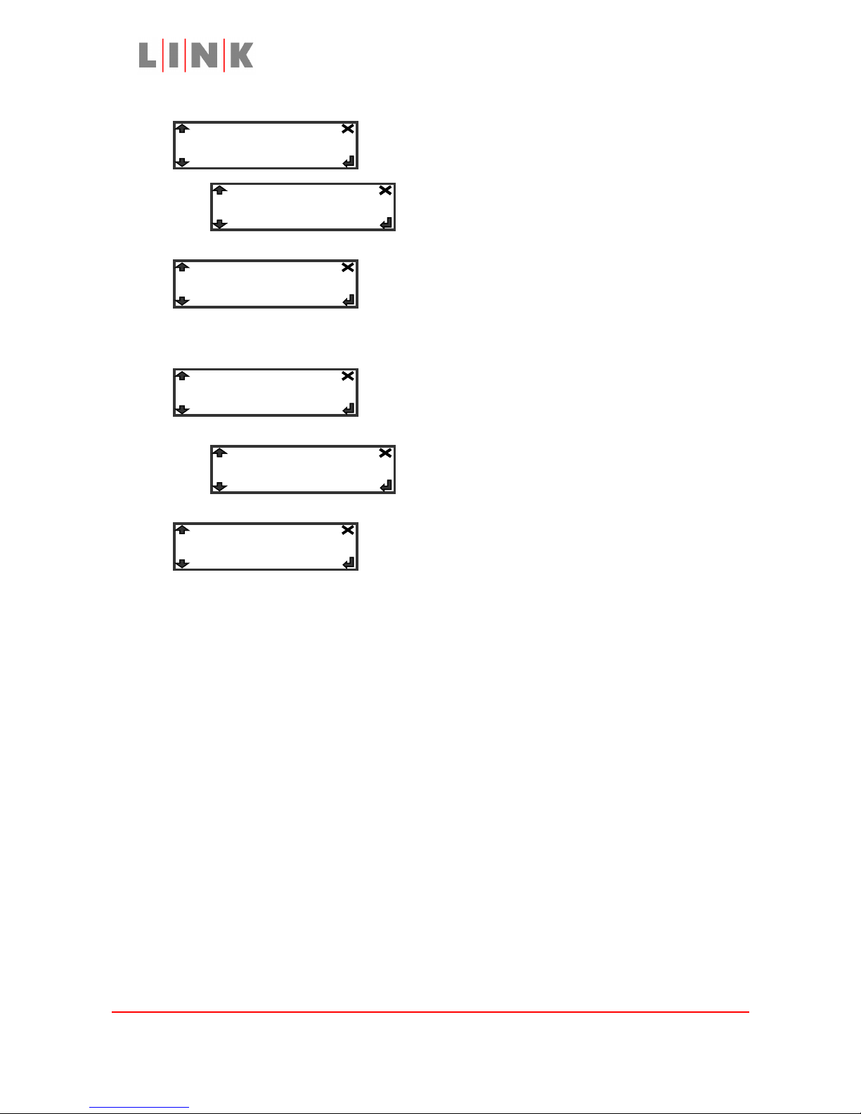
Selecting Off turns off the status LEDs (the display
backlight turns off automatically 6 seconds after the
last button press)
The Temperature entry shows the current internal
temperature of the L1125. The internal fan will try to
keep the internal temperature to 40°C
The Self Test entry is used to run internal tests, the
results are output via the rear RS232 connector
(terminal connection at 9600Baud, 8 data bits, no
parity, 1 stop bit)
This indicates the version of CPLD code inside the
unit. This information may be required by Link
research in the event of a support call.
Images are for illustration only and may differ from components supplied
Link Research Ltd, 23 Watford Metro Centre, Dwight Road, Watford, Herts, WD18 9XA, UK
Telephone +44 1923 200900 (general), +44 1923 200909 (Customer Support)
© Link Research Limited 2004, 2005 Page 14 of 25
Status LEDs: On
-> On-> Off
Temperature: 28C
Self Test: Off
-> Off-> Run
CPLD Version : 4
Page 15

L1125 User Guide
System Setup Guidelines
The Link XPRV system is a state of the art digital wireless camera system. There are many
complicated options but by following a few simple guidelines incredible results can be
achieved.
The LinkXP manual covers the forward path of the system in detail and as such that will not
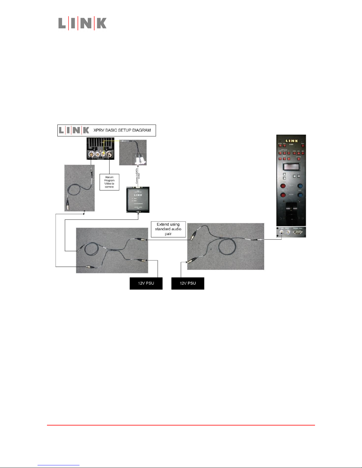
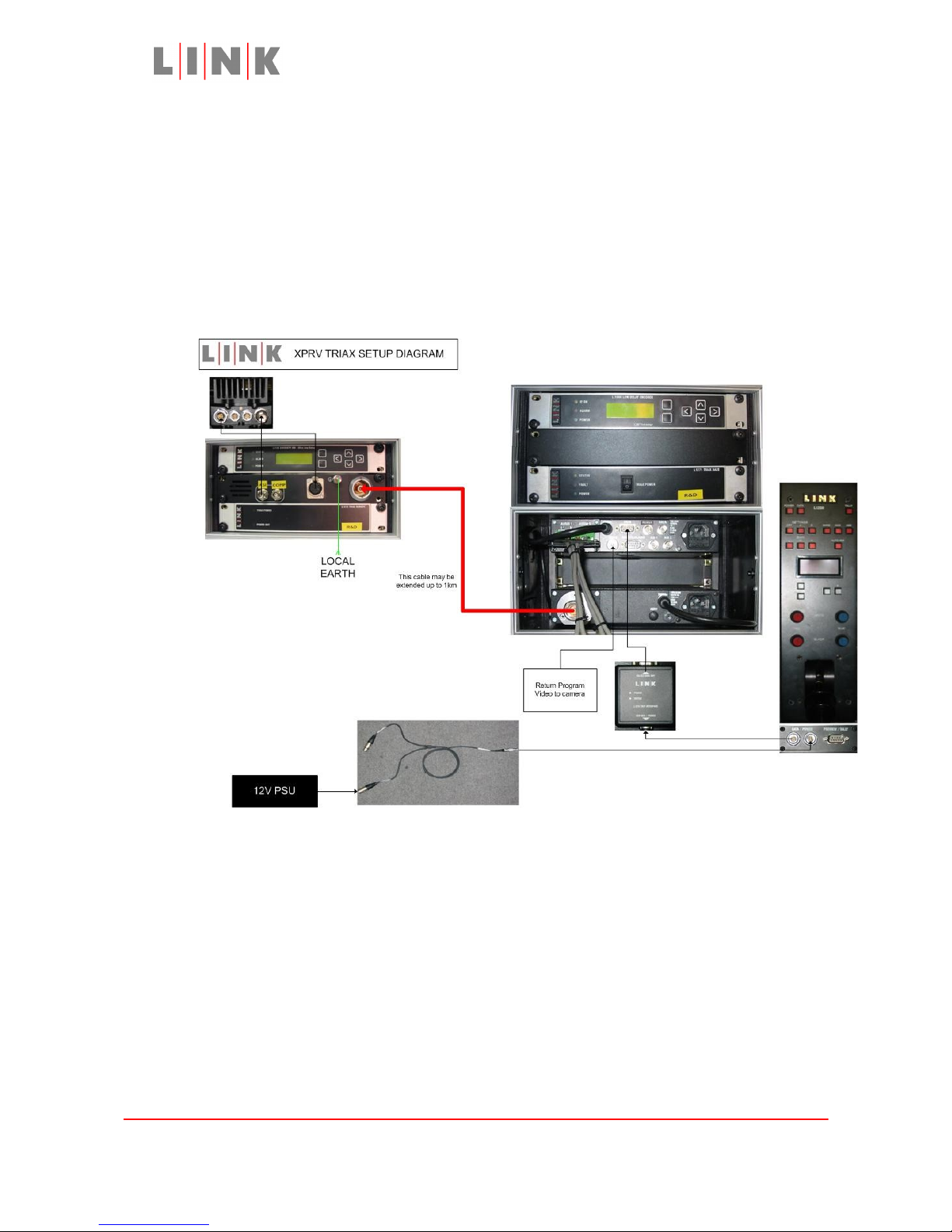
be covered here. Included in the system are two pictorial setup diagrams these indicate
the physical interconnections of the system and which cables to use. The XPRV Basic
setup diagram details how to setup the standard system, while the XPRV Triax diagram
covers the setup of the optional triax system.
The reverse video system can operate with a return frequency in the range 2-
2.11Ghz. When using a forward path frequency in the range 2.2-2.4GHz the Link
L3040 transmit filter must be used on the camera mounted transmitter, when in
the 2.4-2.7GHz range the Link L3041 transmit filter must be used.
It is important that the L1303 XPe transmitter is positioned at least 10m away from the
receiving downconverters ensure no degradation in performance of the forward path link.
Images are for illustration only and may differ from components supplied
Link Research Ltd, 23 Watford Metro Centre, Dwight Road, Watford, Herts, WD18 9XA, UK
Telephone +44 1923 200900 (general), +44 1923 200909 (Customer Support)
© Link Research Limited 2004, 2005 Page 15 of 25
Page 16
L1125 User Guide
System description – Standard
Control data is generated by the OCP, a short breakout cable connects to the OCP to bring
out the serial data and provide power from a local supply. The serial data connections are
terminated in 3 pin XLR connectors to allow a standard audio cable to be used where long
distances are required. The control data is combined with another power supply and fed
into the L1251 OCP interface which translates the data into a new format. The newly
formatted data is fed into the L1303 XPe transmitter along with the reverse video for
transmission to the camera.
Images are for illustration only and may differ from components supplied
Link Research Ltd, 23 Watford Metro Centre, Dwight Road, Watford, Herts, WD18 9XA, UK
Telephone +44 1923 200900 (general), +44 1923 200909 (Customer Support)
© Link Research Limited 2004, 2005 Page 16 of 25
Page 17
L1125 User Guide
System Description – Triax (Optional)
Control data is generated by the OCP, and fed into the L1251 OCP interface which
translates the data into a new format. The newly formatted data is fed into the L1000 Low
delay encoder where it is encoded and modulated with the reverse video. This signal is
sent down the triax cable along with power by the L1271 Triax Base unit. At the far end of
the triax cable the L1272 triax Remote unit removes the power from the cable and feeds
the modulated signal into an L2102 IRD. An ASI signal is taken from this and fed into an
L1303 XPe transmitter for transmission on to the camera.
Images are for illustration only and may differ from components supplied
Link Research Ltd, 23 Watford Metro Centre, Dwight Road, Watford, Herts, WD18 9XA, UK
Telephone +44 1923 200900 (general), +44 1923 200909 (Customer Support)
© Link Research Limited 2004, 2005 Page 17 of 25
Page 18
L1125 User Guide
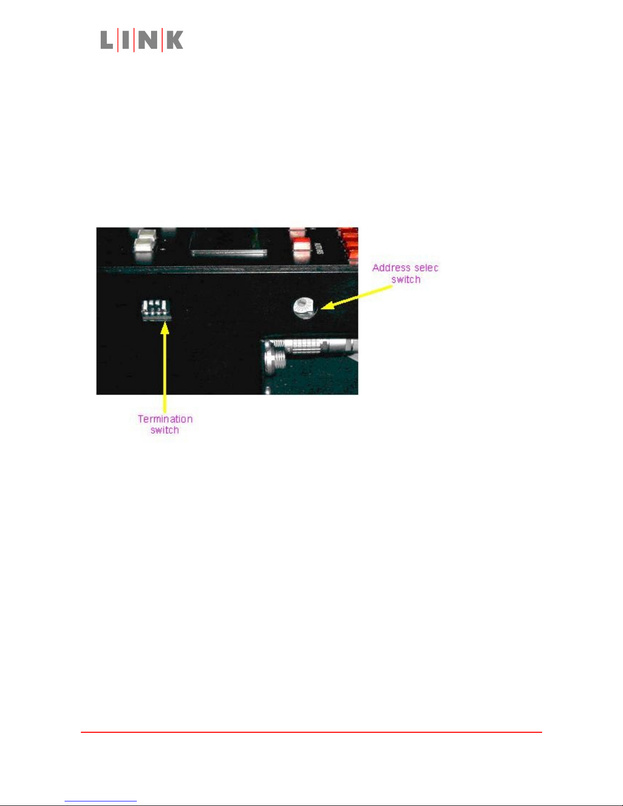
(a)Setting up the L1250 operator’s control panel
Connect the 9-way D-sub connector to the PREVIEW/TALLY connector on the base of the
L1250. The other end of the cable will go to the master switcher or control matrix in the
OB van. (Breakout cable is provided)
Select the unit address using the rotary switch on the right side of the unit. Any number
between 1 and 8 is a valid address. Do not select 0 as this is a special test mode. Both
L1250 and L1125 must have the same address selected.
Switch positions on the side of the operator’s control panel
When the OCP is turned on, it will initially display RF cam and the address of the unit. After
a short time, it will then display a camera type. Using the + and – buttons cycles through a
list of camera types: the camera type shown in the display is the currently selected
camera.
When using multiple OCP’s the final one in the chain must have its termination switch set
to ON (Down). If only one OCP is used then this is the last and only one in the chain and
therefore requires termination to be set to ON.
Images are for illustration only and may differ from components supplied
Link Research Ltd, 23 Watford Metro Centre, Dwight Road, Watford, Herts, WD18 9XA, UK
Telephone +44 1923 200900 (general), +44 1923 200909 (Customer Support)
© Link Research Limited 2004, 2005 Page 18 of 25
Page 19

L1125 User Guide
Cable & Connector Details
L0016 Control Cable for Philips LDK100/200 cameras
Lemo
FGG0B305CLAD52Z
9-Way D-Type socket Signal
1 3 Receive data
2 7 CTS
3 8 RTS
4 2 Transmit data
L0017 Control Cable for Sony 950 cameras
Lemo
FGG0B305CLAD52Z
Hirose MXR-8PA-8PB Signal
1 1 Tx+ from
camera
2 2 Tx– from camera
3 3 Tx+ to camera
4 4 Tx- to camera
L0023 Control Cable for Sony DXC-Dxx Cameras
Lemo
FGG0B305CLAD52Z
Hirose HR10A-10P-10P Signal
3 7 RTS
4 4 Transmit data
L0024 Control Cable for Ikegami cameras
Lemo
FGG0B305CLAD52Z
Hirose HR10B-10PA10PG
Signal
1 3 Receive data
2 4 CTS
3 1 RTS
4 2 Transmit data
L0026 Tally/Preview Cable
9-way D-Type socket 3-way XLR
plug
3-way XLR
socket
Signal
2 2 Not used Tally +
6 3 Not used Tally –
3 Not used 2 Preview Contact 1
4 Not used 3 Preview Contact 2
Images are for illustration only and may differ from components supplied
Link Research Ltd, 23 Watford Metro Centre, Dwight Road, Watford, Herts, WD18 9XA, UK
Telephone +44 1923 200900 (general), +44 1923 200909 (Customer Support)
© Link Research Limited 2004, 2005 Page 19 of 25
Page 20
L1125 User Guide
L1125 Headphone/Audio connector (mating connector is 5-way XLR
plug)
5-way XLR socket Signal
1 Microphone in +
2 Microphone in 3 GND
4 Headphone Out
5 Headphone Out
L1125 & L1303 Power connector (mating connector Lemo
FGG1B304CLAD62Z)
Lemo
FGG1B304CLAD62Z
Signal
1 GND
2
3
4 +Ve
L1125 RS232 connector (mating connector is Lemo
FGF0B306CLAD52Z)
Lemo EEF0B306CLL Signal
1 External RS232 Rx
2 External RS232 Tx
3 GND
4 Tally 1 + (300mA max)
5 Tally 2 - (300mA max)
6 GND
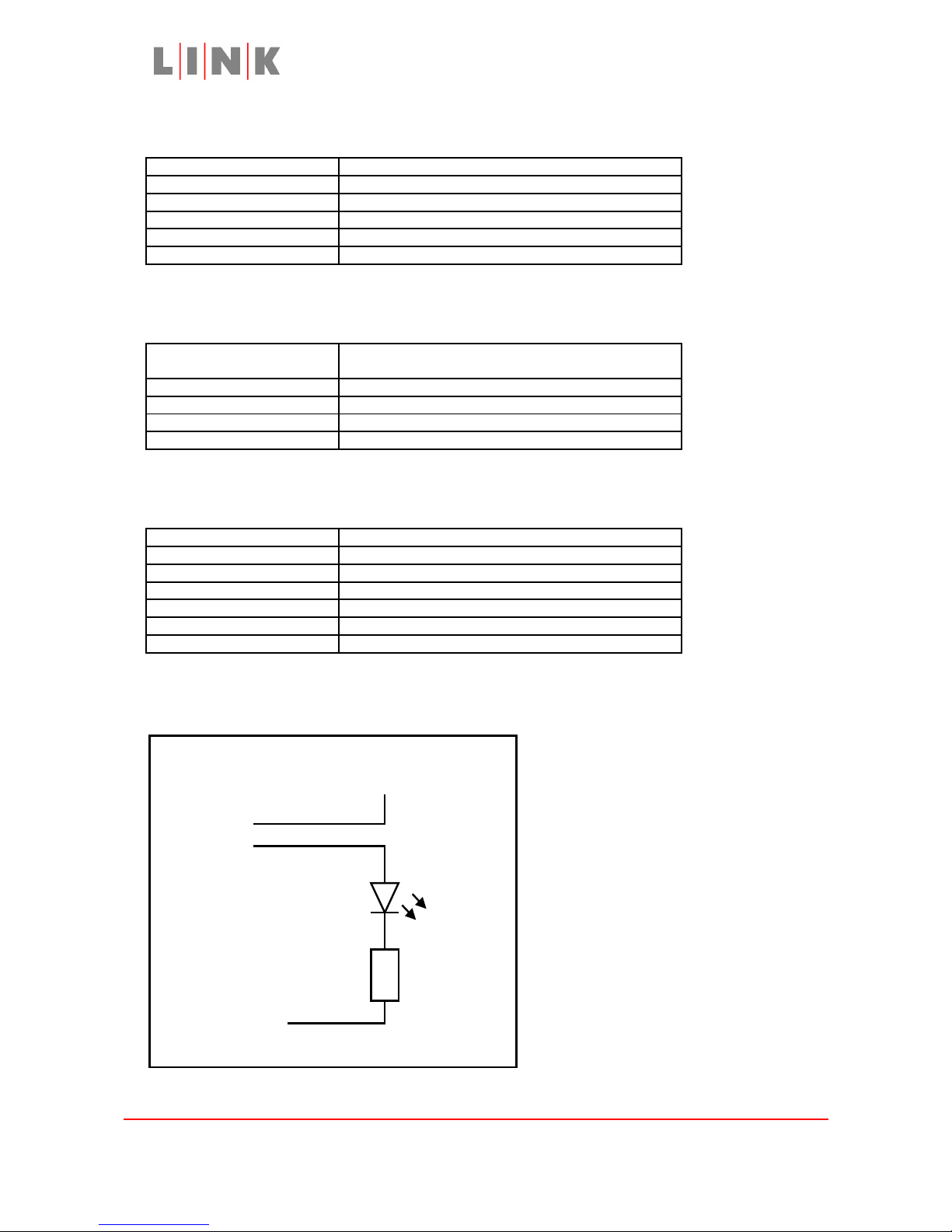
Example external Tally Circuit
Battery -ve
Pin 5
Pin 4
Battery +ve
600R (Approx)
Images are for illustration only and may differ from components supplied
Link Research Ltd, 23 Watford Metro Centre, Dwight Road, Watford, Herts, WD18 9XA, UK
Telephone +44 1923 200900 (general), +44 1923 200909 (Customer Support)
© Link Research Limited 2004, 2005 Page 20 of 25
Page 21

L1125 User Guide
L1125 EXT connector (mating connector is Lemo
FGG0B305CLAD52Z)
Lemo EEG0B305CLL Signal
1 Receive or Tx+ from camera
2 CTS or TX- from camera
3 RTS or Tx+ to camera
4 Transmit or Tx- to camera
5 No connection
Images are for illustration only and may differ from components supplied
Link Research Ltd, 23 Watford Metro Centre, Dwight Road, Watford, Herts, WD18 9XA, UK
Telephone +44 1923 200900 (general), +44 1923 200909 (Customer Support)
© Link Research Limited 2004, 2005 Page 21 of 25
Page 22
L1125 User Guide
Upgrading L1125 Software
L1125 software upgrades may be obtained from the Link Research website
www.linkres.co.uk , follow the Support -> Customers Login link, enter the username and
password provided by Link Research then go to Support -> Support Options -> Firmware
Download. Click on the link for L1125 software to download a zip file with the latest code,
then unzip the downloaded file to a directory on your PC.
The terminal program Tera Term is needed to upgrade the L1125 software. This can be
obtained from the site http://hp.vector.co.jp/authors/VA002416/teraterm.html. To install
Tera Term, download the zip file from the website (ttermp23.zip) and extract the zip to an
empty directory on your PC. Run the Setup program from that directory to install the
software, the directory used to extract the zip file can be deleted after installation.
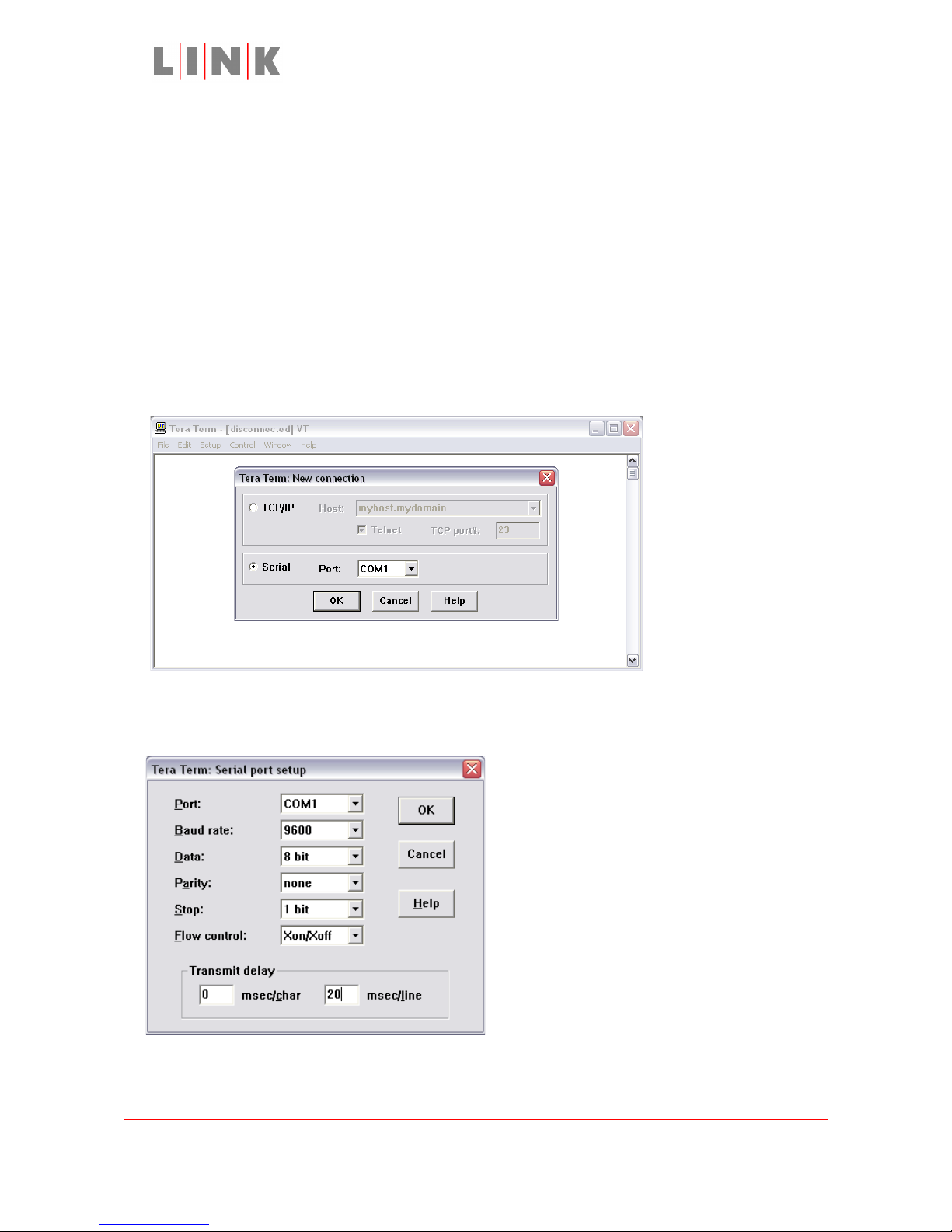
When Tera Term is run it will show a window like that below. Choose the Serial option and
select the COM port you will be using to reprogram the L1125.
Go to Setup -> Serial Port… to access the port configuration menu and configure it with the
settings shown below.
N.B. Make sure flow control is Xon/Xoff and Transmit Delay is 20
msec/line.
Images are for illustration only and may differ from components supplied
Link Research Ltd, 23 Watford Metro Centre, Dwight Road, Watford, Herts, WD18 9XA, UK
Telephone +44 1923 200900 (general), +44 1923 200909 (Customer Support)
© Link Research Limited 2004, 2005 Page 22 of 25
Page 23
L1125 User Guide
Connect the PC to the RS232 connector on the rear of the L1125 using the L0002 LinkXP
TX Data Remote Lead, the PC should be connected to the lead marked “DATA”.
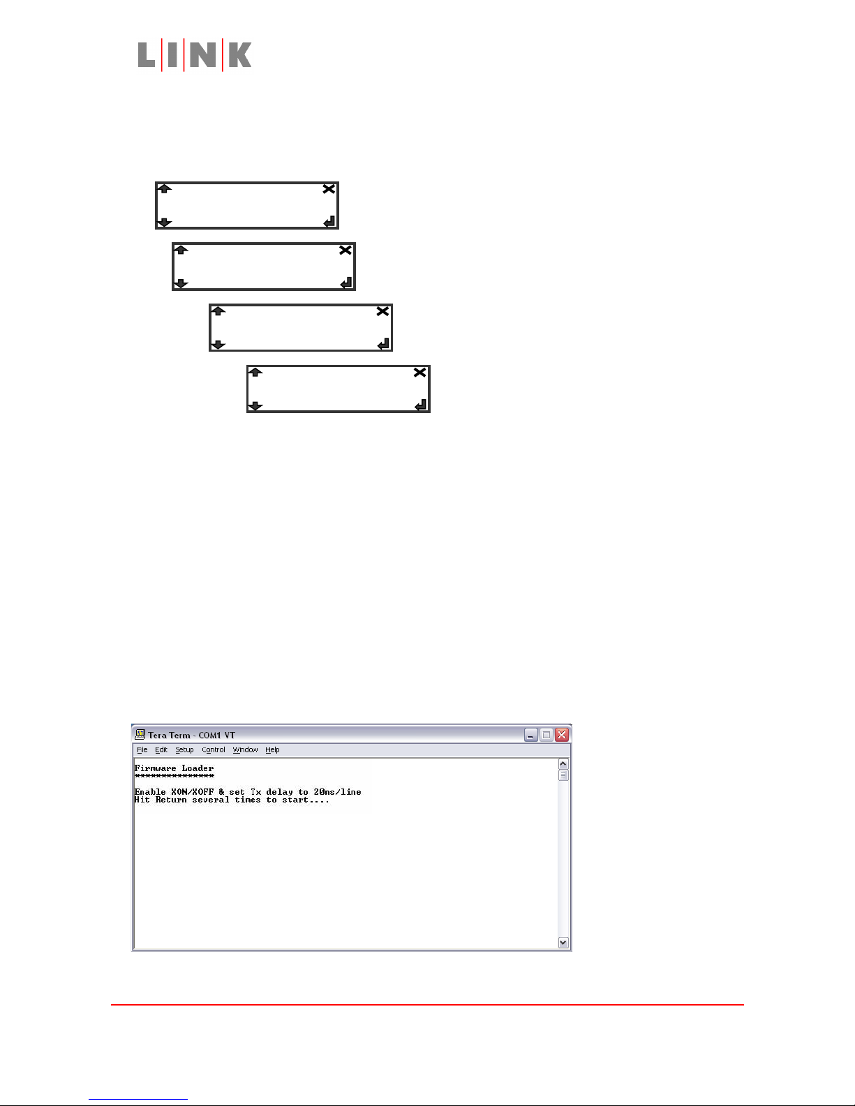
Go to the Unit menu on the L1125 and select Upgrade… -> Control Panel… -> Reprogram
If running V0.40 software this is the “Yes”
option. After pressing Enter the display
will show “Programming…”
Warning: Do not select Reprogram if you are not ready
to go through the full upgrade process. When upgrading
the L1125 camera back software the upgrade must be
completed before the L1125 can be used again. If the
upgrade does not complete successfully or power is
interrupted during the upgrade the L1125 will appear to
be dead. Once the software upgrade has been
successfully completed normal operation will be
restored.
A message similar to the following should appear on the Tera Term window, if it does not,
check the serial cable connections and make sure the PC is connected to the DATA lead,
not the CONTROL lead.
Images are for illustration only and may differ from components supplied
Link Research Ltd, 23 Watford Metro Centre, Dwight Road, Watford, Herts, WD18 9XA, UK
Telephone +44 1923 200900 (general), +44 1923 200909 (Customer Support)
© Link Research Limited 2004, 2005 Page 23 of 25
Upgrade…
Control Panel…
-> Reprogram
Unit…
Page 24
L1125 User Guide
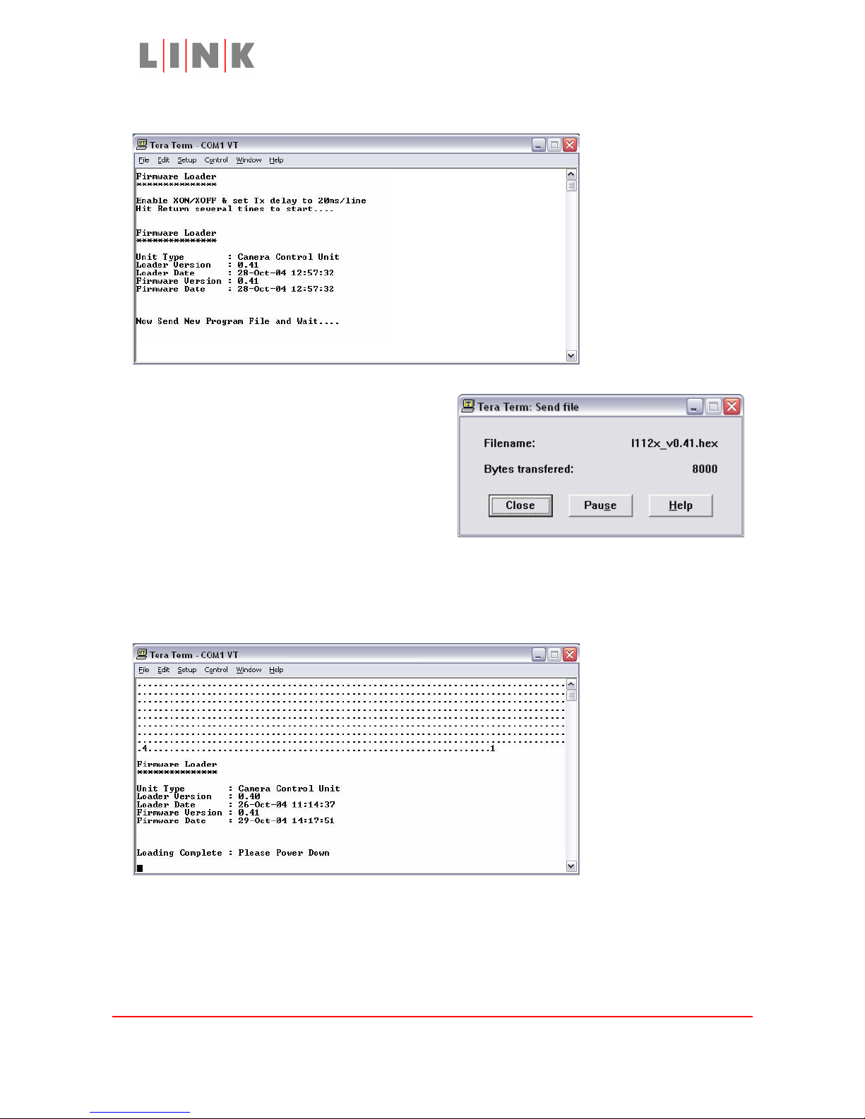
After hitting the Return key several times a message similar to the following will appear:
Select File -> Send File… on Tera Term and
choose the unzipped file downloaded from the
Link Research website (the file extension will
be .hex, e.g. l112x_v0.41.hex).
The file download takes approximately 4
minutes, during which the Tera Term window
will show a series of full stops. The progress of
the download is shown in a separate window
like that opposite.
When the upgrade process has completed the Tera Term window will show a window like
that below with the message “Loading Complete : Please Power Down”. At this point
the upgrade is complete and the L1125 can be turned off.
If the upgrade process does not complete successfully, turn the L1125 power off and back
on and repeat the process of sending the file. If the Tera Term window shows a checksum
failure, make sure that the serial port setup has Flow Control selected as Xon/Xoff and
Transmit Delay set to 20 msec/line and repeat the process of sending the file.
Images are for illustration only and may differ from components supplied
Link Research Ltd, 23 Watford Metro Centre, Dwight Road, Watford, Herts, WD18 9XA, UK
Telephone +44 1923 200900 (general), +44 1923 200909 (Customer Support)
© Link Research Limited 2004, 2005 Page 24 of 25
Page 25

L1125 User Guide
Troubleshooting
Symptom: L1125 appears to be dead. Power LED does not come on, display
remains blank
Possible causes: Rear power switch is off (power switch is adjacent to the rear
connectors, the switch on the battery bracket is not used with L1125)
Power lead is not connected
L1125 has been set to software upgrade mode and is awaiting new
software. To check for this, connect terminal software (e.g. Tera Term)
via the rear RS232 connection with settings of 9600 Baud, no parity,
8 data bits, 1 stop bit, XON/XOFF flow control and 20ms transmit
delay at end of line. Turn power off/on, if the L1125 is in
reprogramming mode it will send a message on the RS232
connection (refer to the Upgrading L1125 Software section for further
information).
Symptom: Camera does not react to Operators Control Panel control
adjustments
Possible causes: The Camera Address setting (in the Reverse Path menu) is not the
same as the OCP address (switch setting on side of OCP)
The Frequency setting (in the Reverse Path menu) is not the same as
the XPe Transmitter Interface.
The correct camera type has not been selected (in the Reverse Path
menu)
The wrong transmit filter is being used.
The camera requires an external control lead but the lead is not
fitted or not making proper connection
The camera supports selection of either internal or external control
links but the corresponding Cam I/F setting in the Reverse Path menu
has not been correctly configured
If the Data light on the OCP does not flicker when the iris control is
moved then the OCP is not communicating with the L1251 Interface,
check that the OCP address is not set to 0 and that the cable
between OCP and L1251 is properly connected and undamaged
If the L1251 status light and OCP Data light are working correctly,
remove the L1125 from the Camera, set the camera type (in the
Reverse Path menu) to Ikegami Handheld and check that the RX
status LED is on when the OCP iris control is moved. If the LED stays
off the L1125 is not receiving commands.
For further information, including the latest list of supported cameras and
details of any adaptor plate modifications or cables required, refer to the
Support Options section of the Link Research website www.linkres.co.uk or
contact the Support Line +44 1923 200909
Images are for illustration only and may differ from components supplied
Link Research Ltd, 23 Watford Metro Centre, Dwight Road, Watford, Herts, WD18 9XA, UK
Telephone +44 1923 200900 (general), +44 1923 200909 (Customer Support)
© Link Research Limited 2004, 2005 Page 25 of 25
 Loading...