

Page 1
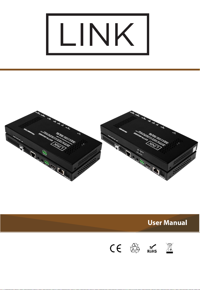
LINK EXT70-4KUHDE
4K@60 4:4:4 HDR HDBaseT Extender with ARC
Version: V1.0.0
Page 2
.
Page 3

This equipment has been tested and found to comply with the limits for a
Class B digital device, pursuant to Part 15 of the FCC Rules. These limits are
designed to provide reasonable protection against harmful interference in a
residential installation. This equipment generates uses and can radiate radio
frequency energy and, if not installed and used in accordance with the
instructions, may cause harmful interference to radio communications.
However, there is no guarantee that interference will not occur in a particular
installation. If this equipment does cause harmful interference to radio or
television reception, which can be determined by turning the equipment off
and on, the user is encouraged to try to correct the interference by one or
more of the following measures:
-- Reorient or relocate the receiving antenna.
-- Increase the separation between the equipment and receiver.
-- Connect the equipment into an outlet on a circuit different from that to
which the receiver is connected.
-- Consult the dealer or an experienced radio/TV technician for help.
Changes or modifications not expressly approved by the party responsible for
compliance could void the user's authority to operate the equipment.
Page 4
Table of Contents
Introduction
Overview
Features
Package Contents
Specifications
Transmitter
Receiver
Cable Specifications
Panel Layout
Transmitter
Receiver
Connections & Installations
Audio DIP Switch Control
ARC Mode
TOSLINK IN Mode
Operating with IR
IR Control
Control the Display
Control the Source
Operate with RS232
RS232 Pinout
RS232 Pass Through
Trouble Shooting
Steps of Regular Troubleshooting Routine
Warranty Terms and Conditions
Page 5

Introduction
Overview
LINK EXT70-4KUHDE is an HDBaseT Extender. It supports 4K@60
4:4:4 with HDR and HDCP 2.2 compliant, offers the distribution of
uncompressed UHD video, audio, power, and IR together up to
100m/330ft over a single Cat X cable.
With a feature set including transmission of uncompressed 4K@60Hz UHD
video, HDCP 2.2 compatibility, Dolby and DTS HD audio, bi-directional IR
control, it offers the added benefit of an incredibly low-profile for a greatly
reduced form factor behind the screen for even more convenience and ease
of installation at the display zone.
By the DIP switch of Audio Output on the receiver, it’s able to configure
the ARC channel feed by TV (with ARC support), or auxiliary S/PDIF Input
port. This unit also provides an HDMI audio de-embedding with phoenix
analog connector.
Its proprietary one way PoE technology ensures that the
transmitter unit powers the receiver unit, with visual LED indication for
power supply to units and signal status to show established connection
between connected devices.
1
Page 6

2
Features
4K/UHD capability @60 Hz with 4:4:4 Chroma sampling, plus support for
HDR formats.
HDCP 2.2 compliant.
Supports HD signal transmission up to 100 meters (1080p) and 70 meters
(4K@60Hz YUV 4:4:4) via a single Cat 5e/6 cable.
Supports HD signal transmission up to 100 meters (1080p) and 100
meters (4K@60Hz YUV 4:4:4) via a single Cat 6a/7 cable.
Receiver to transmitter audio return via ARC or optical coax pathway .
HDMI audio de-embedding with phoenix analog connector.
Extends RS232, IR and Ethernet control signals.
Automatic EDID management.
Visual LED indication.
Page 7

3
Package Contents
1 x Transmitter EXT70-4KUHDE
1 x Receiver EXT70-4KUHDE
1 x Power Adapter (DC 12V 3A)
3 x Phoenix Male Connector (3.5mm 3 Pin)
1 x IR Emitter Cable
1 x IR Broadband Receiver Cable (30KHz~50KHz)
1 x AC IR Coupler Cable
4 x Mounting Brackets
Page 8

4
Specifications
Technical
Input
1 x HDMI
Input Signal Type
HDMI with 4K
Input/Output Resolution
Support
800x6008, 1024x7688, 1280x7688,
1280x8008, 1280x9608, 1280x10248,
1360x7688, 1366x7688, 1440x9008,
1600x9008, 1600x12008, 1680x10508,
1920x10808, 1920x12008, 3840x2160
2,3,5,8
,
4096x2160
2,3,5,8
1 = at 23.98 Hz, 2 = at 24 Hz, 3 = at 25 Hz,
4 = at 29.97 Hz, 5 = at 30 Hz, 6 = at 50 Hz,
7 = at 59.94 Hz, 8 = at 60 Hz, 9 = at 75 Hz;
Maximum Data Rate
18 Gbps
Input Video Level
0.5-1.0 V p-p
Input DDC Signal
5V p-p
Maximum Pixel Clock
594MHz
Output
1 x HDBT
Output Signal Type
HDBT
Video Impedance
100 Ω
General
Operating Temperature
0°C to 45°C (32°F to 113°F)
Storage Temperature
-20°C to 70°C (-4°F to 158°F)
Humidity
10% to 90%, non-condensing
Transmitter
Page 9

5
ESD Protection
±8kV(Air-gap discharge)/
±4kV(Contact discharge)
Surge Protection
Voltage: ±1 kV
Electrical Fast
Transient/Burst
Data communication cord: 1 kV
Power cord : 2 kV
Power Supply
DC 12V 3A
Power Consumption
(Maximum)
Receiver is powered by transmitter:
22.38W (1080P)
27W (4K@60Hz YUV 4:4:4)
Transmitter and receiver are powered
separately:
6.32W (1080P)
8.68W (4K@60Hz YUV 4:4:4)
Device Dimension
(W x H x D)
195mm x 21mm x 94.8mm/7.68’’ x 0.83’’ x
3.73’’
Product Weight
0.4kg/0.88lb
Receiver
Video
Input
1 x HDBT
Input Signal Type
HDBT
Input/Output Resolution
Support
800x6008, 1024x7688, 1280x7688,
1280x8008, 1280x9608, 1280x10248,
1360x7688, 1366x7688, 1440x9008,
1600x9008, 1600x12008, 1680x10508,
1920x10808, 1920x12008, 3840x2160
2,3,5,8
,
4096x2160
2,3,5,8
Page 10

6
1 = at 23.98 Hz, 2 = at 24 Hz, 3 = at 25 Hz,
4 = at 29.97 Hz, 5 = at 30 Hz, 6 = at 50 Hz,
7 = at 59.94 Hz, 8 = at 60 Hz, 9 = at 75 Hz;
Maximum Data Rate
18Gbps
Input Video Level
0.5-1.0 V p-p
Input DDC Signal
5V p-p
Maximum Pixel Clock
594MHz
Output
1 x HDMI
Output Signal Type
HDMI with 4K
Video Impedance
100 Ω
General
Operating Temperature
0°C to 45°C (32°F to 113°F)
Storage Temperature
-20°C to 70°C (-4°F to 158°F)
Humidity
10% to 90%, non-condensing
ESD Protection
±8kV(Air-gap discharge)/
±4kV(Contact discharge)
Surge Protection
Voltage: ±1 kV
Electrical Fast
Transient/Burst
Data communication cord: 1 kV
Power cord : 2 kV
Power Supply
DC 12V 3A
Power Consumption
(Maximum)
Transmitter is powered by receiver:
20.46W (1080P)
26.45W (4K@60Hz YUV 4:4:4)
Transmitter and receiver are powered
separately:
9.6W (1080P)
10.69W (4K@60Hz YUV 4:4:4)
Device Dimension
(W x H x D)
195mm x 21mm x 94.8mm/7.68’’ x 0.83’’ x
3.73’’
Page 11
7
Product Weight
0.4kg/0.88lb
Certification
CE, FCC
Cable Specifications
Cable Type
Supported Video
Cat5e/6
100m
1080P@60Hz 36bpp
70m
1080P@60Hz 48bpp
1080P@60Hz 3D
4K@60Hz YUV 4:4:4
Cat6a/7
100m
Note: LINK recommends use of straight-through Category cables wired
to T568B standard.
Range
Page 12
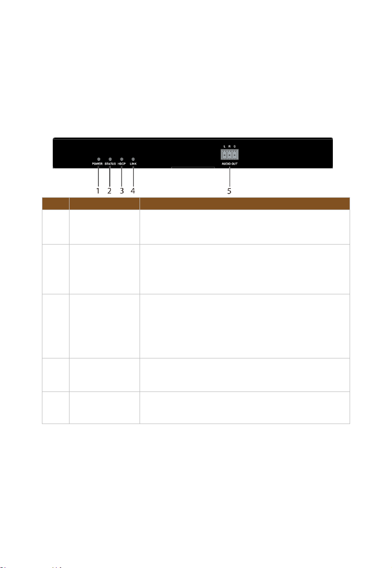
8
Panel Layout
Name
Description
1
POWER LED
ON: The transmitter is powered on.
OFF: The transmitter is powered off.
2
STATUS LED
Flashing Slowly:
The transmitter is working properly.
OFF: The transmitter is not working properly.
3
HDCP LED
ON: HDCP video is being transmitted.
Flashing Quickly: Non-HDCP video is being
transmitted.
OFF: No HDMI signal.
4
LINK LED
ON: HDBT link is normal
OFF: No HDBT Link
5
AUDIO OUT
HDMI audio de-embedding, connects to audio
system like AV receiver.
Transmitter
No.
Front Panel
Page 13
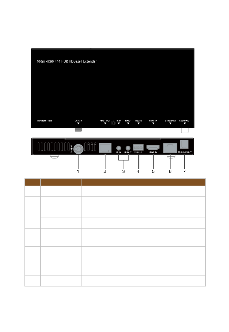
9
Rear Panel
No.
Name
Description
1
Power
12V DC power input
2
HDBT OUT
Connects to HDBT IN port of receiver
3
IR IN
Connects to IR receiver
IR OUT
Connects to IR emitter
4
RS232
5
HDMI IN
Connects to an HDMI source
6
ETHERNET
7
TOSLINK OUT
Connects to audio system like AV receiver
Connects to control system for RS232 Pass
Through
Passes Ethernet connections from TX unit to RX
unit.
Page 14
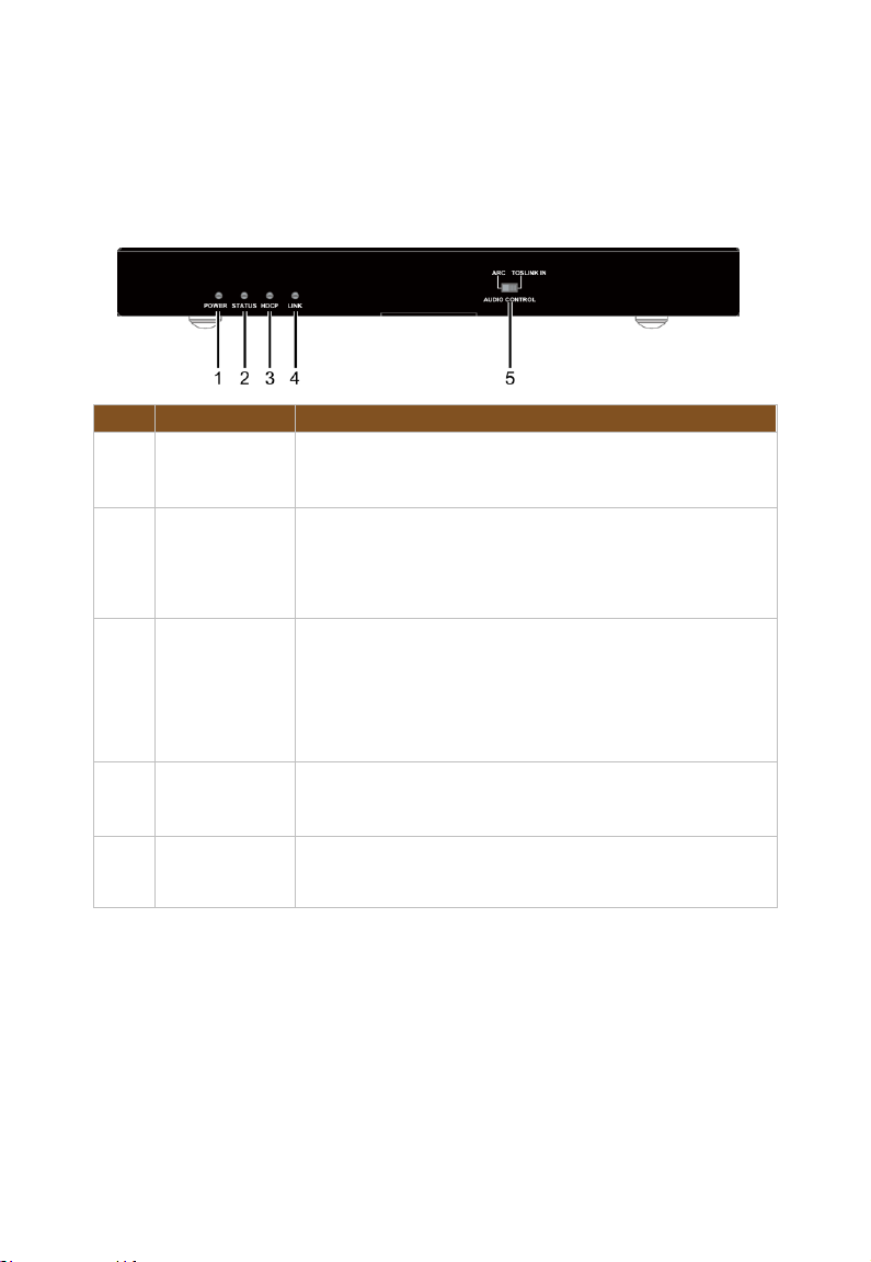
10
Receiver
No.
Name
Description
1
POWER
LED
ON: The receiver is powered on.
OFF: The receiver is powered off.
2
STATUS
LED
Flashing Slowly:
The receiver is working properly.
OFF: The receiver is not working properly.
3
HDCP LED
ON: HDCP video is being transmitted.
Flashing Quickly: Non-HDCP video is being
transmitted.
OFF: No HDMI signal.
4
LINK LED
ON: HDBT link is normal
OFF: No HDBT Link
5
AUDIO
CONTROL
Front Panel
ARC, use ARC utilizing HDMI
TOSLINK IN, passes optical audio from RX
to TX unit
Page 15
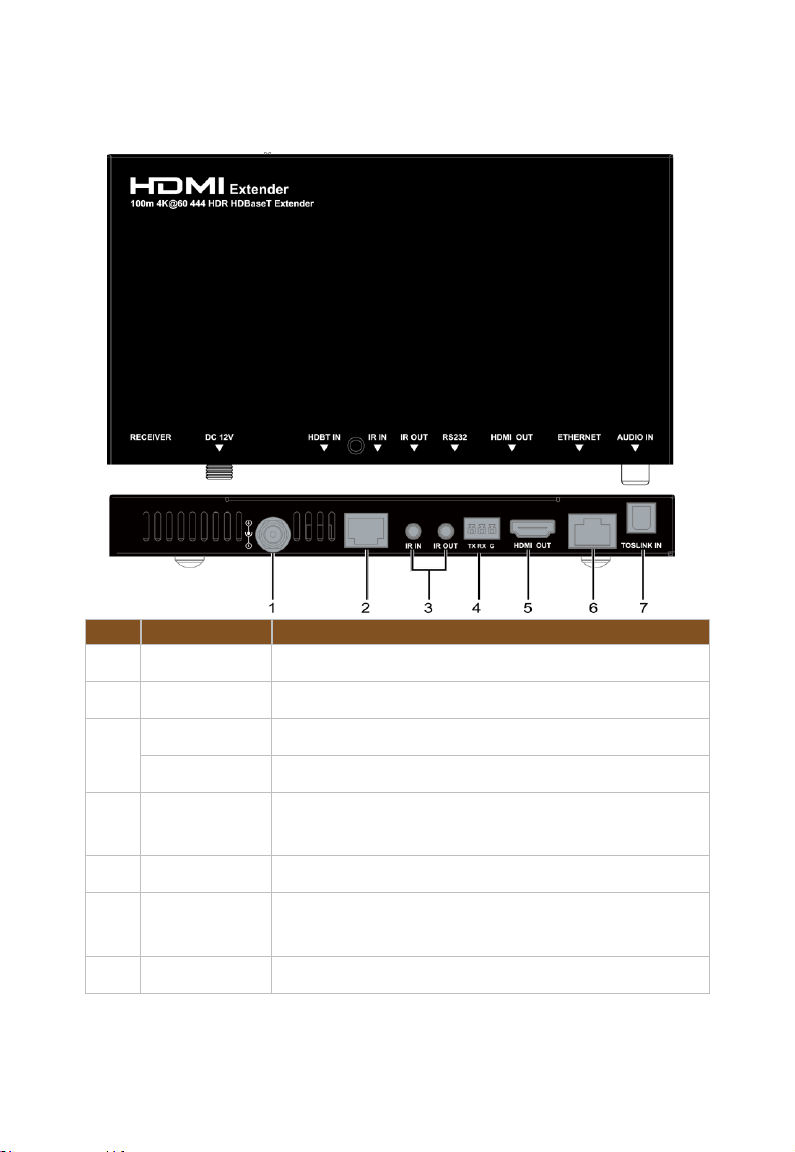
11
Rear Panel
No.
Name
Description
1
Power
12V DC power input
2
HDBT IN
Connects to HDBT OUT port of transmitter
3
IR IN
Connects to IR receiver
IR OUT
Connects to IR emitter
4
RS232
5
HDMI OUT
Connects to an HDMI display
6
ETHERNET
7
TOSLINK IN
Connects to audio system on TOSLINK IN mode
Connects to control system for RS232 Pass
Through
Passes Ethernet connections from TX unit to RX
unit
Page 16

12
Connections and Installations
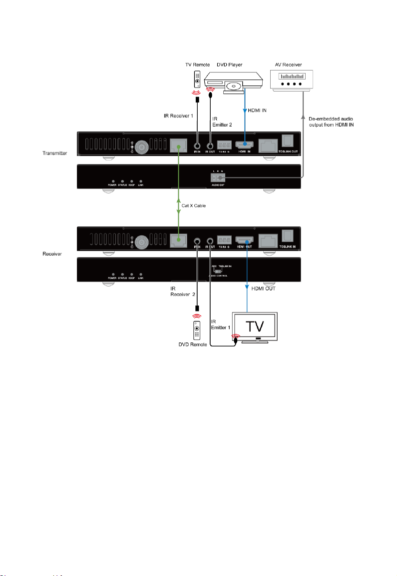
1. Using quality HDMI cables, connect an HDMI source (such as Blu-ray,
games console, satellite/cable TV, media server etc.) to HDMI IN port of
Transmitter.
2. Connect the audio system in the figure to the AUDIO OUT port of the
Transmitter.
3. Connect a good quality, terminated Cat X cable between the HDBT
OUT of the Transmitter to the HDBT IN of the Receiver.
4. Connect the HDMI display device such as TV in the figure to the HDMI
OUT of the Receiver.
5. For two-way IR control of connected sources and displays from either
location, first, connect IR Emitters to the IR OUT ports of the
Transmitter and Receiver, and then insert IR Receivers into the IR IN
ports of the Transmitter and Receiver.
6. For the audio DIP switch output on the receiver, please refer to the
Audio DIP Switch Control Section.
7. Connect the included 12V power supply to the transmitter or receiver.
The PoE function carries power along the length of the cable to power
the other one.
Check Power, Status, and HDCP & Link lights are illuminated on both units to
indicate successful connection, with a lit HDCP light illustrating the presence
of encryption within the signal. Power and Link are static lights. Status should
be blinking.
Page 17
13
Page 18

14
Audio DIP Switch Control
The Extender features an Audio DIP Switch that can be used to control audio
output.
ARC Mode
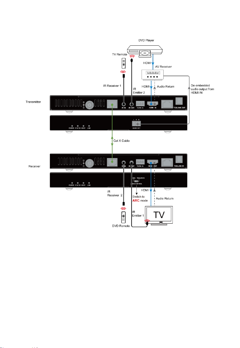
Note: When you want to configure ARC channel feed by TV:
Ensure AV System and TV support ARC function and CEC should be
ON.
Connect AV System and TV through ARC- enabled HDMI Ports.
Connect the AV System to HDMI IN port of Transmitter, connect a TV to
HDMI Out port of Receiver. Switch the DIP switch to ARC mode, switch TV to
the audio source you want to be sent back, and set the AV System to the
ARC channel. The audio signal of TV through HDMI OUT port will be
transmitted to the AV System connected to HDMI IN Port of Transmitter.
(Figure 1)
TOSLINK IN Mode
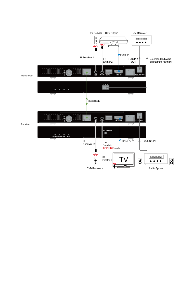
When you configure the auxiliary optical input, please switch it to TOSLINK
IN mode and connect an audio system to the TOSLINK IN port of Receiver,
and an Audio System such as an AV Receiver to TOSLINK OUT port of
Transmitter. Audio signal from TOSLINK IN port will pass through to
TOSLINK OUT port. (Figure 2)
Page 19
15
Figure 1
Page 20
16
Figure 2
Page 21

17
Operating with IR
IR Control
IR pass-through function allows you to control the source from the display
location or control the display from source location.
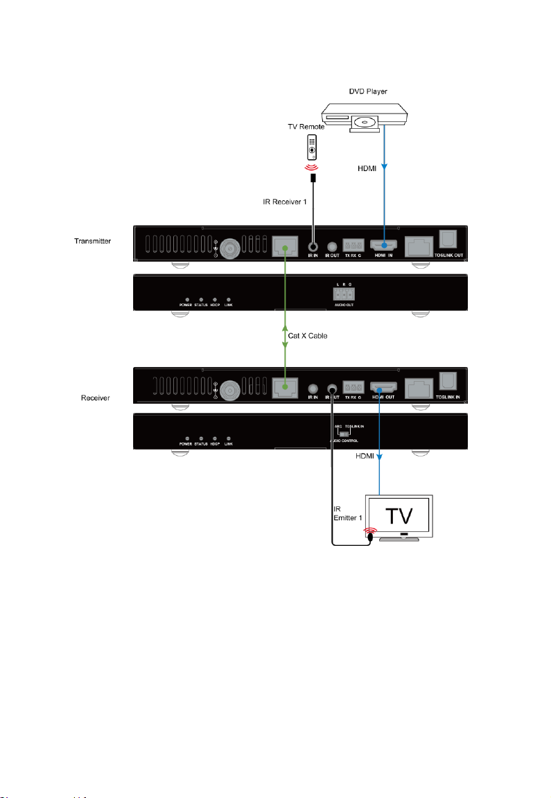
Control the Display
In this case, IR IN port in Transmitter is connected to a broadband IR
receiver and IR OUT port in Receiver is connected to an IR emitter. You
can control the TV from the DVD location with the TV remote.
Page 22
18
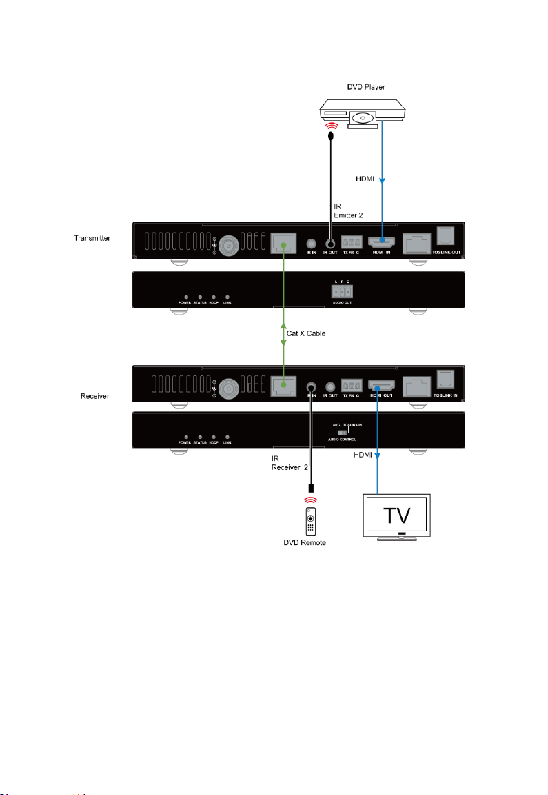
Control the Source
In this case, IR OUT port in Transmitter is connected to an IR emitter and IR
IN port in Receiver is connected to a broadband IR receiver. You can
control the DVD player from the TV location with the DVD remote.
Page 23
19
Page 24
20
Operate with RS232
Control System
TX
TX
RX
RX
GND
GND
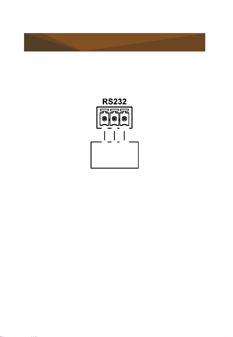
RS232 Pinout
The following figure shows the RS232 pinout. Please connect with Phoenix
Connectors provided.
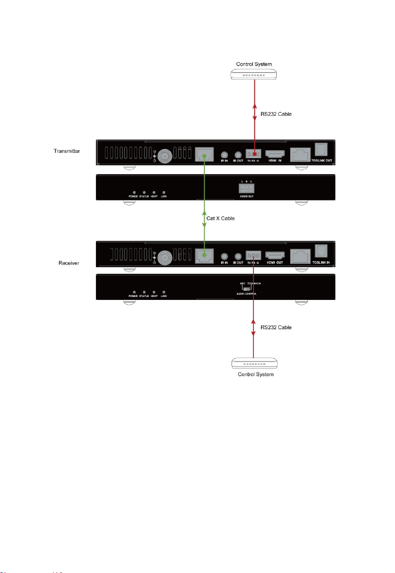
RS232 Pass Through
According to the bi-direction RS232 pass through function, you can use two
RS232 control systems for serial communication by connecting to the
devices via serial cables in order to control the source device or the display.
Page 25
21
Page 26

22
Trouble Shooting
Troubleshooting Steps
1. Power: Please make sure all devices are powered on (the sources,
extender and display).
2. Indicator: Please make sure LED indicators of the extender are normal
according to user manual.
3. Devices: Please make sure picture can be shown normally when
connecting source to display devices directly.
4. Cable: Plug in and unplug HDMI/Cat X cable or try another HDMI/Cat
X cable. Please make sure the specific cable length is within the
transmission range in the user manual Specification section. Cat
5e/6/6a/7 cable is recommended, do not use Cat 5 cable. Please make
sure the two connectors of one Cat X cable are the same standard
(EIA/TIA 568B).
5. Compatibility: Please test other source and display devices to
determine if it is a compatibility issue.
Page 27

23
Warranty Terms and Conditions
For the following cases LINK shall charge for the service(s) claimed for the
products if the product is still remediable and the warranty card becomes
unenforceable or inapplicable.
1. The original serial number (specified by LINK) labeled on the
product has been removed, erased, replaced, defaced or is illegible.
2. The warranty has expired.
3. The defects are caused by the fact that the product is repaired,
dismantled or altered by anyone that is not from a LINK
authorized service partner. The defects are caused by the fact that the
product is used or handled improperly, roughly or not as instructed in
the applicable User Guide.
4. The defects are caused by any force majeure including but not limited to
accidents, fire, earthquake, lightning, tsunami and war.
5. The service, configuration and gifts promised by salesman only but not
covered by normal contract.
6. LINK preserves the right for interpretation of these cases above and to
make changes to them at any time without notice.
Page 28
WWW.MSTRBRAND.COM
 Loading...