

Page 1
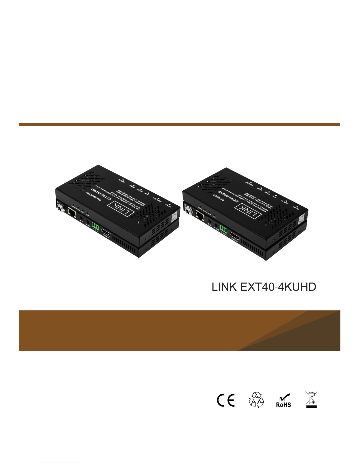
LINK EXT40-4KUHD
4K@60 4:4:4 HDR HDBaseT Extender
User Manual
Version: V1.0.1
Page 2
1
Important Safety Instructions
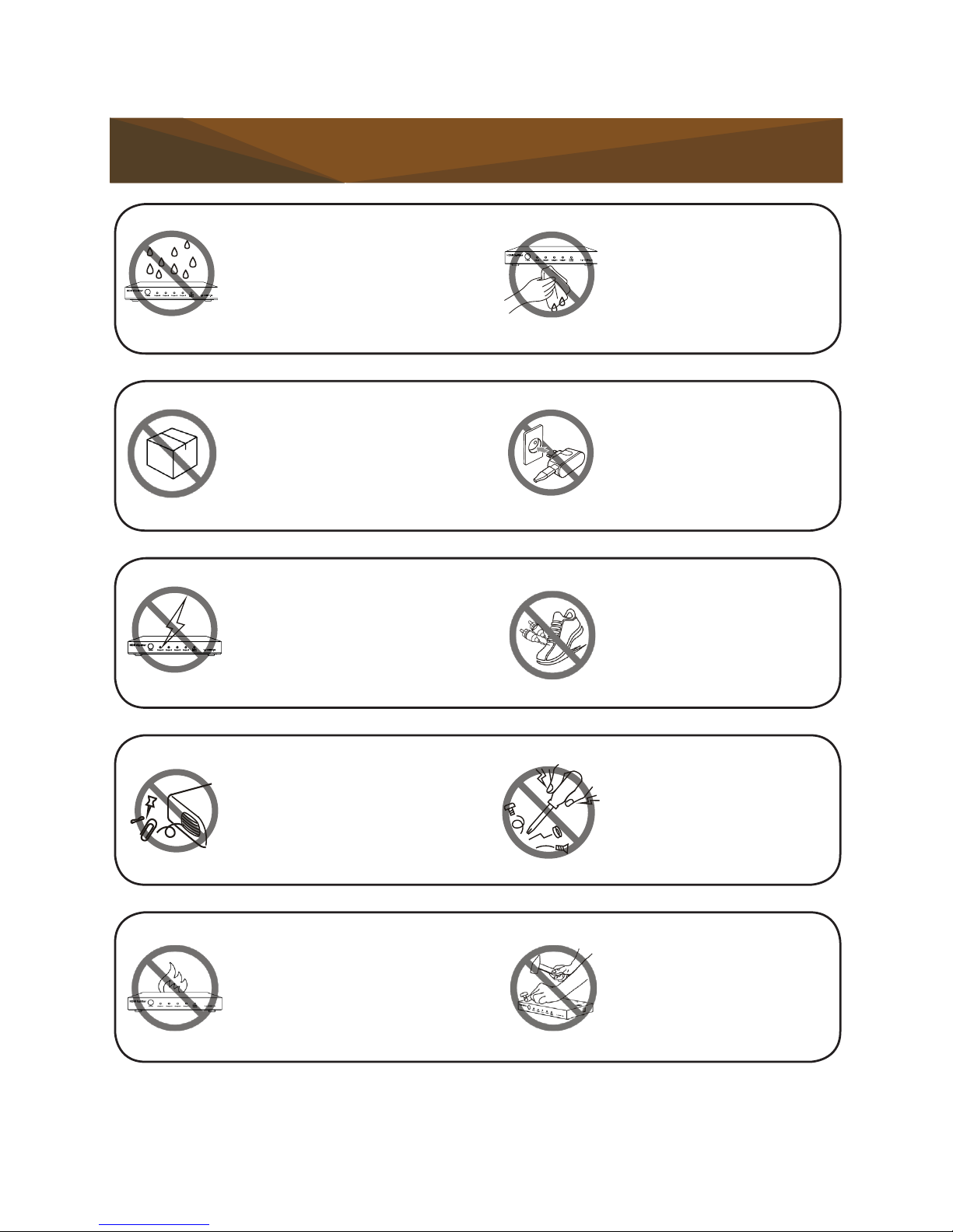
1. Do not expose this apparatus to
rain, moisture, dripping or splashing
and that no objects lled with liquids,
such as vases, shall be placed on the
apparatus.
2. Do not install or place this unit
in a bookcase, built-in cabinet or in
another confined space. Ensure the
unit is well ventilated.
3. To prevent risk of electric shock or
fire hazard due to overheating, do not
obstruct the unit's ventilation openings
with newspapers, tablecloths,
curtains, and/or similar items.
4. Do not install near any heat
sources such as radiators, heat
registers, stoves, or other apparatus
(including amplifiers) that produce
heat.
5. Do not place sources of naked
flames, such as lighted candles, on
the unit.
6. Clean this apparatus only with dry
cloth.
7. Unplug this apparatus during
lightning storms or when unused for
long periods of time.
8. Protect the power cord from being
walked on or pinched particularly at
plugs.
9. Only use attachments / accessories
specied by the manufacturer.
10. Refer all servicing to qualified
service personnel.
Page 3

2
Table of Contents
Introduction �������������������������������������������������������������������������������������������������
3
Overview .................................................................................................
3
Features ..................................................................................................
4
Package Contents ...................................................................................
4
Specication ............................................................................................
5
Transmitter .........................................................
...............................
5
...................................
7
Receiver .........................................................
Panel Layout .......................
....................................................................
9
...............................
9
Transmitter ........... ..............................................
Receiver .........................................................
..................................
11
Installation Instructions ���������������������������������������������������������������������������
13
IR Pass Through ...................................................................................
15
RS232 Pass Through ............................................................................
17
Trouble Shooting ��������������������������������������������������������������������������������������
18
Steps of Regular Troubleshooting Routine.......................................
18
Typical Questions .............................................................................
19
Warranty Terms and Conditions �������������������������������������������������������������
21
Page 4

3
Introduction
Overview
LINK EXT40-4KUHD is a slim HDBT transmitter receiver set with HDCP 2.2
compliant. It supports resolutions up to 4K@60Hz 4:4:4 8bit, transporting Ultra
HD/4K video with HDR, audio, bi-directional IR and power up to 131ft (40m) and
1080P signals up to 230ft (70m) over a single CATX cable.
EXT40-4KUHD features bi-directional PoCC, requiring only one
power adapter connected to either transmitter or receiver to power both units. Bi-
directional IR pass through allows users to control the source at the display location
or control the display at the source location with ease. RS232 pass through
supports serial communication.
The transmitter and receiver are easy to install. They are space saving and offer
ideal solutions for homes, ofces, digital entertainment centers, control centers,
conference rooms, schools and corporate training environments.
Page 5

4
• Supports HDMI 2.0 with 4K@60Hz 4:4:4 8bit and HDCP 2.2
• Supports HDR (High Dynamic Range) format
• Over a Cat 6a/7 cable, HDMI signal transport up to 230ft (70m) at 1080P and
131ft (40m) at 4K@60Hz (4:4:4)
• Over a Cat 5e/6 cable, HDMI signal transport up to 197ft (60m) at 1080P and
115ft (35m) at 4K@60Hz (4:4:4)
• Bi-directional PoCC, one power supply at either transmitter or receiver side
can power both units
• Supports bi-directional IR/RS232 pass through
• Slim profile, space saving and easy-to-install
Features
Package Contents
• 1 x Transmitter
• 1 x
Receiver
• 1 x Power Supply (DC 18V 1A)
• 1 x IR Emitter
• 1 x Broadband IR Receiver (30-50 KHz)
• 1 x IR-AC IR Coupler Cable
• 2 x Phoenix Male Connector (3.5mm, 3 Pins)
• 4 x Mounting Bracket
Page 6

5
Technical
Input 1 x HDMI IN
Input Signal Type HDMI with HDCP 2.2
Input/Output Resolution Supported
SMPTE:
1280x720P
1,2,3,4,5,6,7,8
, 1920x1080I
6,8
,
1920x1080P
1,2,3,4,5,6,7,8
, 3840x2160
2,3,5,6,8
,
4096x2160
2,3,5,6,8
VESA:
800x600
8
, 1024x7688, 1280x7688,
1280x800
8
, 1280x9608, 1280x10248,
1360x768
8
, 1366x7688, 1400x10508,
1440x900
8
, 1600x9008, 1600x12008,
1680x1050
8
, 1920x1200
8
1 = at 23.98 Hz, 2 = at 24 Hz, 3 = at 25 Hz, 4
= at 29.97 Hz, 5 = at 30 Hz, 6 = at 50 Hz, 7 =
at 59.94 Hz, 8 = at 60 Hz
Maximum Data Rate 18 Gbps
Input Video Level 0.5-1.0 V p-p
Maximum Pixel Clock 600MHz
Output 1 x HDBT
Output Signal Type HDBT
Video Impedance 100ohms
Specification
Transmitter
Page 7

6
General
Operating Temperature
0°C to 45°C (32°F to 113°F),
10% to 90%, non-condensing
Storage Temperature
-20°C to 70°C (-4°F to 158°F)
10% to 90%, non-condensing
Humidity 10% to 90%, non-condensing
Power Supply DC 18V 1A
Power Consumption (Max) 4.8W
Device Dimension
(W x H x D)
5.39'' x 0.61'' x 2.93''
(136.8 mm ×15.4 mm × 74.5 mm)
Product Weight 0.53lb (0.24kg)
Certication CE, FCC
Cable Specification:
Note: LINK recommends the use of T568B straight-through Category cables.
Cable Type Range Supported Video
HDMI
49ft (15m) 1080P@60Hz
33ft (10m) 4K@30Hz
10ft (3m) 4K@60 Hz 4:4:4 8 bit with HDR
CAT5e/6
197ft (60 m) 1080P@60Hz 36 bpp
115ft (35 m)
1080P@60Hz 48 bpp
1080P@60Hz 3D
4K@60 Hz 4:4:4 8bit with HDR
CAT6a/7
230ft (70 m) 1080P@60Hz 36 bpp
131ft (40 m)
1080P@60Hz 48 bpp
1080P@60Hz 3D
4K@60Hz 4:4:4 8bit with HDR
Page 8

7
Technical
Input 1 x HDBT
Input Signal Type HDBT
Input/Output Resolution Supported
SMPTE:
1280x720P
1,2,3,4,5,6,7,8
, 1920x1080I
6,8
,
1920x1080P
1,2,3,4,5,6,7,8
, 3840x2160
2,3,5,6,8
,
4096x2160
2,3,5,6,8
VESA:
800x600
8
, 1024x7688, 1280x7688,
1280x800
8
, 1280x9608, 1280x10248,
1360x768
8
, 1366x7688, 1400x10508,
1440x900
8
, 1600x9008, 1600x12008,
1680x1050
8
, 1920x1200
8
1 = at 23.98 Hz, 2 = at 24 Hz, 3 = at 25 Hz, 4
= at 29.97 Hz, 5 = at 30 Hz, 6 = at 50 Hz, 7 =
at 59.94 Hz, 8 = at 60 Hz
Maximum Data Rate 18 Gbps
Input Video Level 0.5-1.0 V p-p
Maximum Pixel Clock 600MHz
Output 1 x HDMI
Output Signal Type HDMI with HDCP 2.2
Video Impedance 100ohms
Receiver
Page 9
8
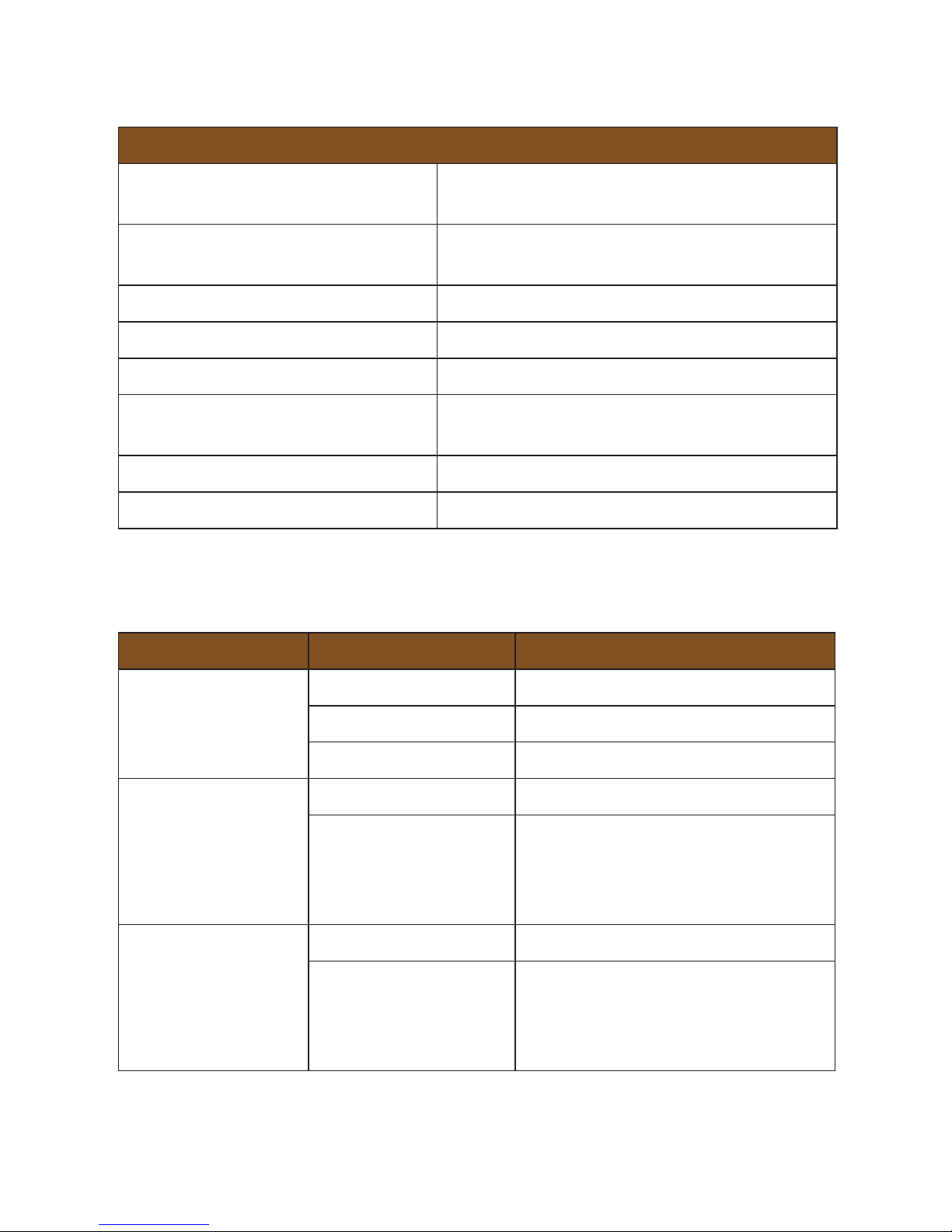
General
Operating Temperature
0°C to 45°C (32°F to 113°F),
10% to 90%, non-condensing
Storage Temperature
-20°C to 70°C (-4°F to 158°F)
10% to 90%, non-condensing
Humidity 10% to 90%, non-condensing
Power Supply DC 18V 1A
Power Consumption (Max) 7.4W
Device Dimension
(W x H x D)
5.39'' x 0.61'' x 2.93''
(136.8 mm ×15.4 mm × 74.5 mm)
Product Weight 0.53lb (0.24kg)
Certication CE, FCC
Cable Specification:
Note: LINK recommends the use of T568B straight-through Category cables.
Cable Type Range Supported Video
HDMI
49ft (15m) 1080P@60Hz
33ft (10m) 4K@30Hz
16ft (5m) 4K@60 Hz 4:4:4 8 bit with HDR
CAT5e/6
197ft (60 m) 1080P@60Hz 36 bpp
115ft (35 m)
1080P@60Hz 48 bpp
1080P@60Hz 3D
4K@60 Hz 4:4:4 8bit with HDR
CAT6a/7
230ft (70 m) 1080P@60Hz 36 bpp
131ft (40 m)
1080P@60Hz 48 bpp
1080P@60Hz 3D
4K@60Hz 4:4:4 8bit with HDR
Page 10
9
Front Panel
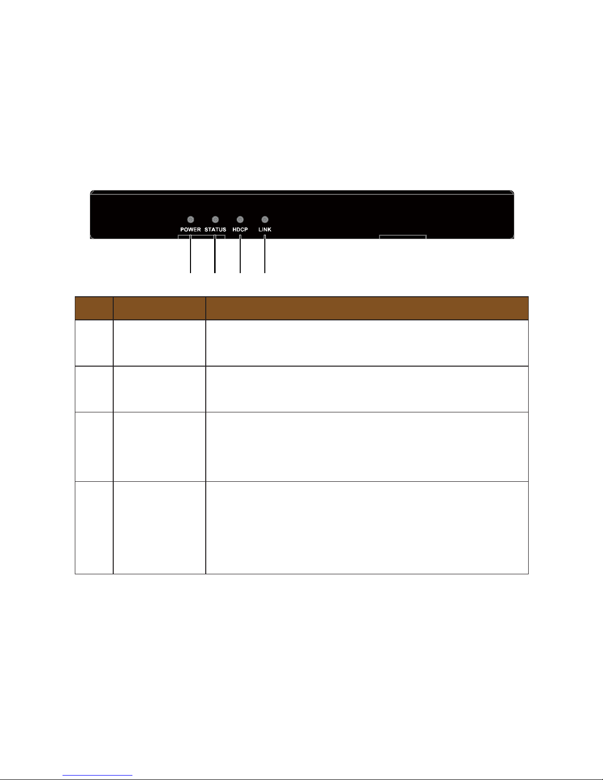
No� Name Description
1
Power LED
(Red)
On: The transmitter is powered on.
Off: The transmitter is powered off.
2
Status LED
(Blue)
Blinking: The transmitter is working properly.
Off: The transmitter is not working properly.
3
HDCP LED
(Blue)
On: HDMI signal is HDCP protected.
Blinking: HDMI signal is not HDCP protected.
Off: No HDMI signal pass through.
4
Link LED
(Green)
On: The link between transmitter and receiver is normal.
Blinking: The link between transmitter and receiver is
abnormal.
Off: No link.
Panel Layout
Transmitter
Page 11
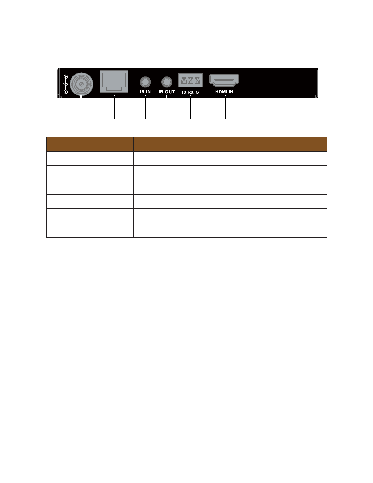
10
No� Name Description
1 DC 18V DC 18V power input
2 HDBT OUT Connect to the receiver
3 IR IN Connect to the supplied IR receiver.
4 IR OUT Connect to the supplied IR emitter.
5 RS232 RS232 pass through
6 HDMI IN Connect to an HDMI source device.
1 2 3 4 5 6
Rear Panel
Page 12
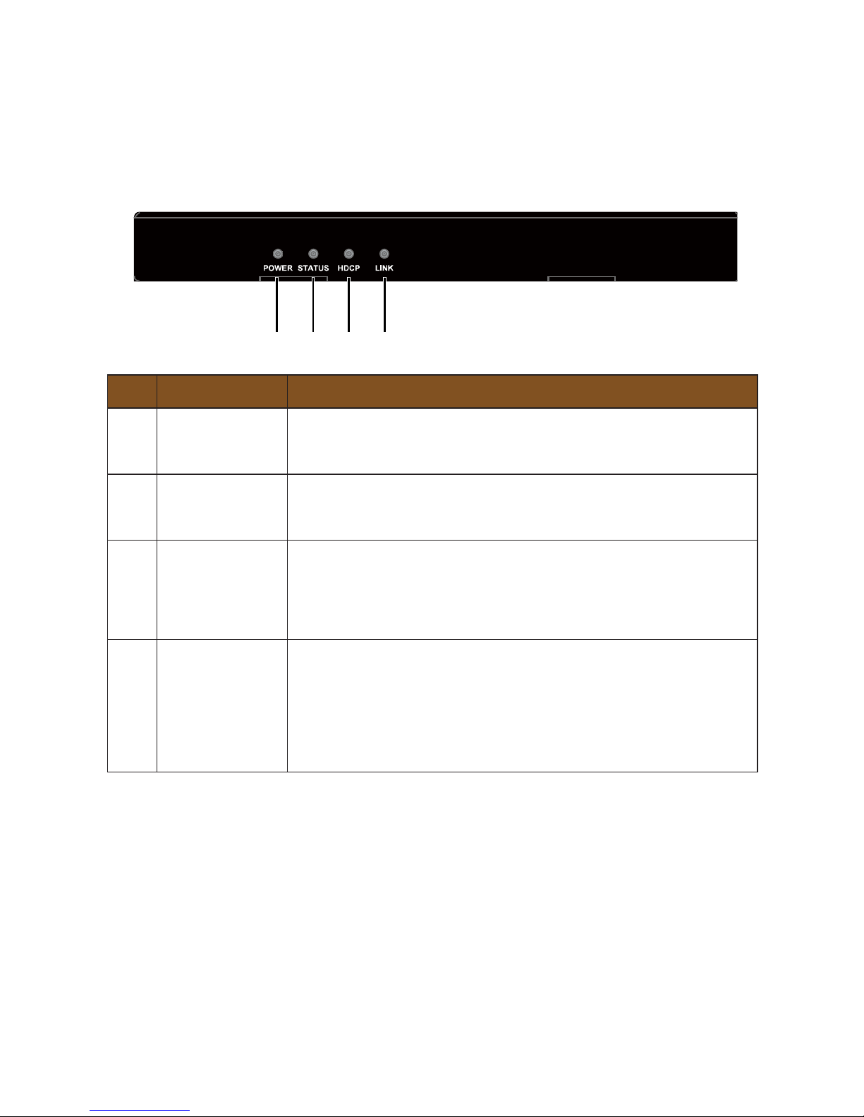
11
No� Name Description
1
Power LED
(Red)
On: The receiver is powered on.
Off: The receiver is powered off.
2
Status LED
(Blue)
Blinking: The receiver is working properly.
Off: The receiver is not working properly.
3
HDCP LED
(Blue)
On: HDMI signal is HDCP protected.
Blinking: HDMI signal is not HDCP protected.
Off: No HDMI signal pass through.
4
Link LED
(Green)
On: The link between transmitter and receiver is normal.
Blinking: The link between transmitter and receiver is
abnormal.
Off: No link.
1 2 3 4
Front Panel
Receiver
Page 13
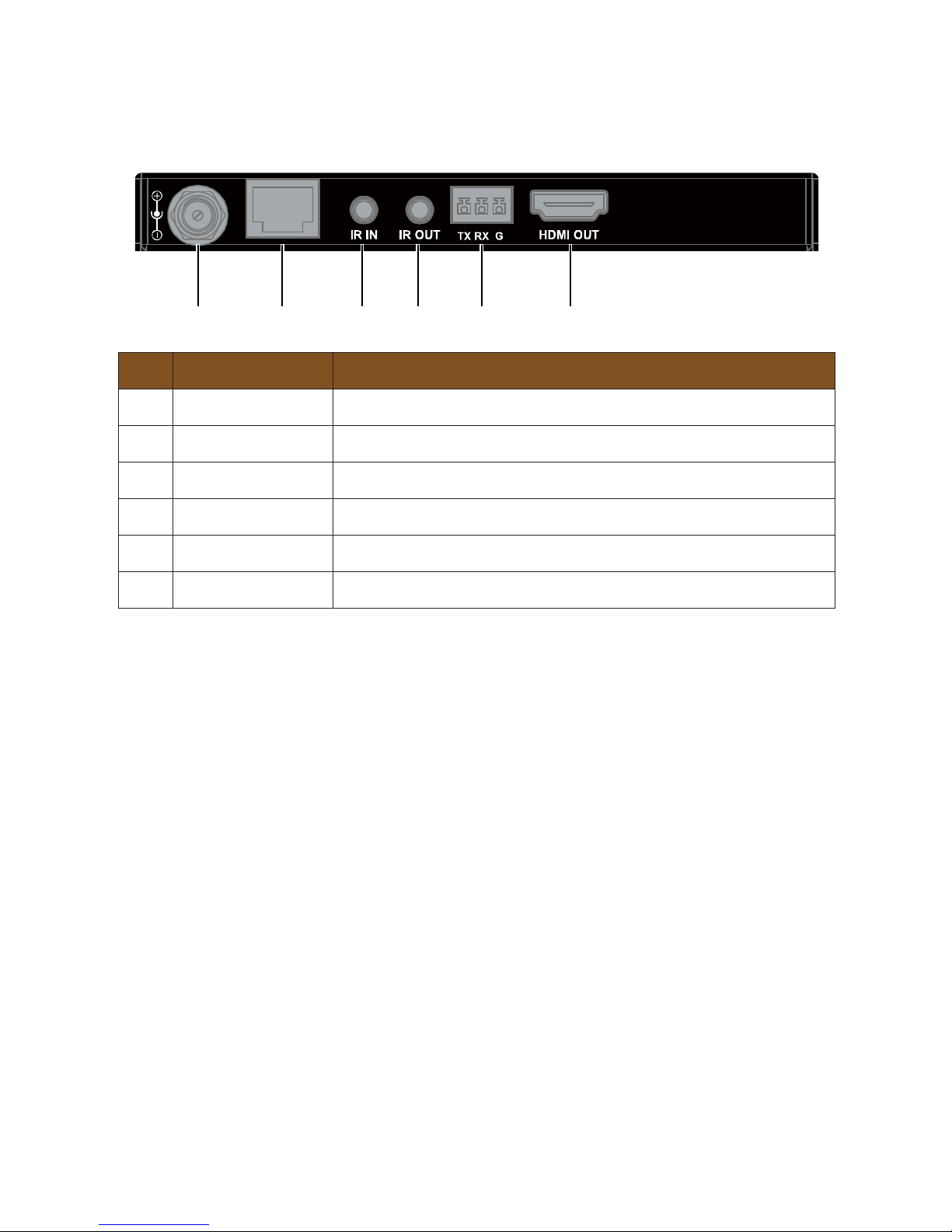
12
No� Name Description
1 DC 18V DC 18V power input
2 HDBT IN Connect to the transmitter
3 IR IN Connect to the supplied IR receiver
4 IR OUT Connect to the supplied IR emitter
5 RS232 RS232 pass through
6 HDMI OUT Connect to an HDMI display device
1 2 3 4 5 6
Rear Panel
Page 14

13
1. Connect an HDMI source (such as Blu-ray player, games console, STB, Apple
TV etc.) to the HDMI IN port of the Transmitter via an HDMI cable.
2. Connect the Transmitter to the Receiver via a Cat X cable on the HDBT ports.
3. Connect an HDMI display to the HDMI OUT port of the Receiver.
4. Connect the IR emitter and IR receiver to the Transmitter and the Receiver
respectively. Users can control the source at the display location or control the
display at the source location as required, please refer to the diagrams in IR
Pass Through Section.
5. Connect the power supply to either the Transmitter or Receiver to power both
units.
Check Power, Status, and HDCP & Link lights are illuminated on both units to indicate
successful connection, with a lit HDCP light
illustrating the presence of encryption
within the signal. Power and Link are static lights. Status should be blinking.
Installation Instructions
Page 15
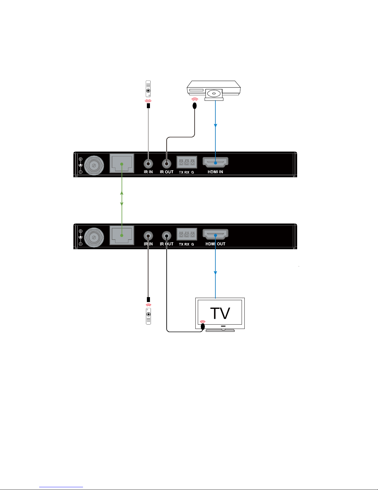
14
Transmitter
Receiver
DVD Remote
TV Remote
DVD
HDMI IN
HDBT OUT
HDBT IN
Cat X cable
HDMI OUT
IR Emitter 1
IR Emitter 2Broadband
IR Receiver 1
Broadband
IR Receiver 2
Page 16
15
IR pass-through function allows users to control the source at the display location or
control the display at the source location.
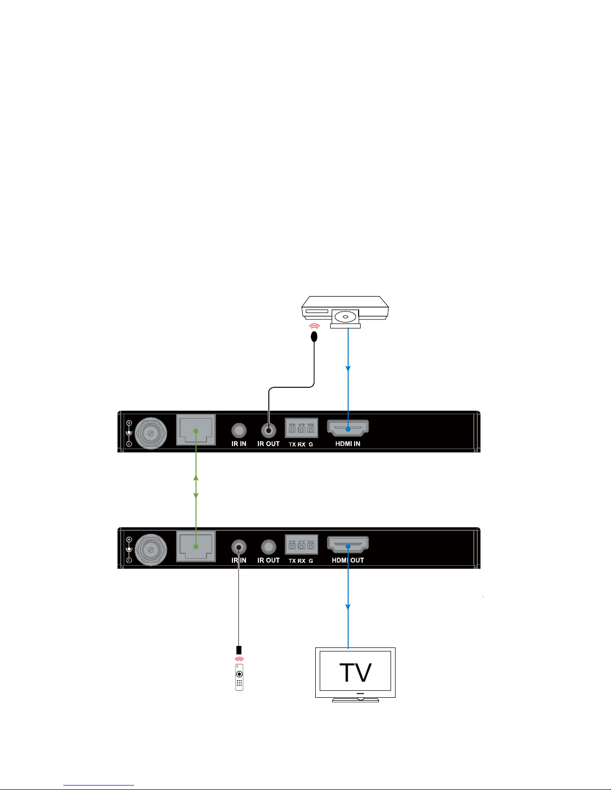
1� Control the source
Connect an IR emitter to the IR OUT port of the Transmitter and a broadband IR
receiver to the IR IN port of the Receiver. Users can control the source at the
display location with the source remote.
DVD Remote
Transmitter
Receiver
DVD
HDMI IN
HDBT OUT
HDBT IN
Cat X cable
HDMI OUT
IR Emitter
Broadband
IR Receiver
Control the source at the display location
IR Pass Through
Page 17
16
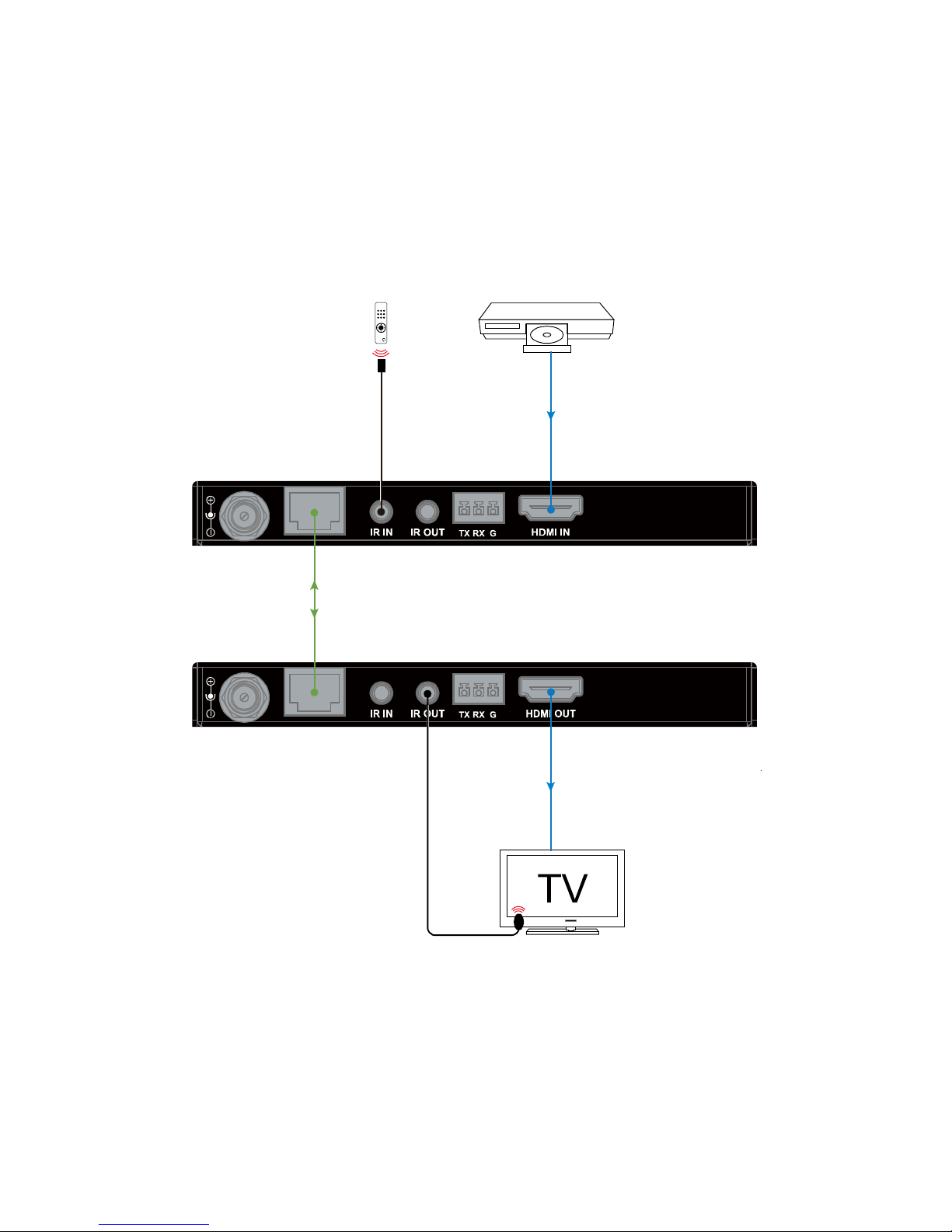
2� Control the display
Connect a broadband IR receiver to the IR IN port of the
Transmitter and an IR
emitter to the IR OUT port of the Receiver. Users can control the TV at the DVD
location with the TV remote.
Transmitter
Receiver
TV Remote
DVD
HDMI IN
HDBT OUT
HDBT IN
Cat X cable
HDMI OUTIR Emitter
Broadband
IR Receiver
Control the display at the source location
Page 18
17
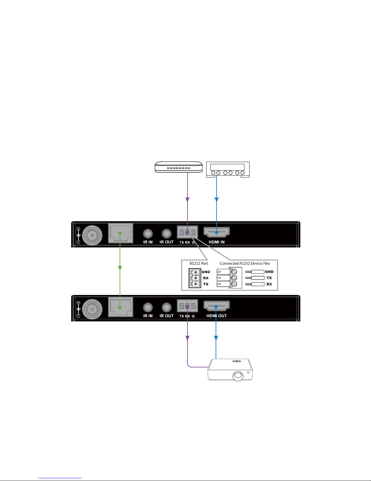
Projector
Transmitter
Receiver
HDBT OUT
RS232 cable
Control System
HDMI IN
STB
Cat X cable
HDMI OUTRS232 cable
RS232 Pass Through
The RS232 port provides a channel to pass through protocol commands to control
third party devices such as
user's source or display. RS232 uses the three
pins that are labeled transmitter, receiver and GND. Connect a host computer or
control system to the RS232 connector. Please refer to the following pin definition
of RS232 during installation.
Page 19

18
1. Power: Please make sure all devices are powered on (the source, extender set
and display).
2. Indicator: Please make sure LED indicators of the transmitter and receiver are
normal according to user manual.
3. Devices: Please make sure picture can be shown normally when connecting
source to display devices directly.
4. Cable: Unplug and
plug in HDMI/Cat X cable or try another HDMI/Cat X cable.
• Please make sure the specific cable length is within the transmission range
listed in below table based on different resolutions.
Resolution and Transmission Range
1080P
4K@60 420
4K@30 444
4K@60 444
HDMI IN 49ft 33ft 10ft
HDMI OUT 49ft 33ft 16ft
Cat 5e/6 197ft 115ft 115ft
Cat 6a/7 230ft 131ft 131ft
• Cat 5e/6/6a/7 cable is recommended, do not use Cat 5 cable. Please make
sure the two connectors of one Cat X cable are the same standard (EIA/TIA
568B).
5.
Compatibility: Please test other source and display devices to determine if it is
a compatibility issue.
Cable
Resolution
Trouble Shooting
Troubleshooting Steps
Page 20

19
1. How can I fix video flash or cut off during the installation?
• Power indicator should be solid on and status indicator should be blinking.
If
not, please check if the power adapter is securely connected.
• Link indicator should be solid on. If it is blinking or off, it is likely a problem
with your Ethernet cable, please change to a qualified cable (Cat5e/6/7,
EIA/TIA 568B) and ensure the cable length is within the maximum distance
(230ft for 1080P, 131ft for 4K).
• HDCP indicator should be solid on or blinking. If it is off, it means no signal
pass through, please check if the HDMI cables are securely connected to
the source and TV, and the Ethernet cable that connects transmitter to
receiver is normal. Try a better HDMI cable or Ethernet cable.
2. How can I fix the IR signal if it is weak or not working?
• Make sure the IR cables are correctly installed according to the diagrams in
IR Pass Through section above.
• Check if the IR emitter head is secured over the center of the device IR
receiver window. The best position may vary depending on the device,
please refer to the device user manual. If the signal is weak, please try to
adjust the position.
• Pay attention to the control angle and distance as below. The control signal
will be better when your controller is pointed at the IR receiver head directly.
Enabled Angle 0° 30°(Horizontal) 15°(Vertical)
Distance 26ft (Max) 15ft (Max) 10ft (Max)
Typical Questions
Page 21
20
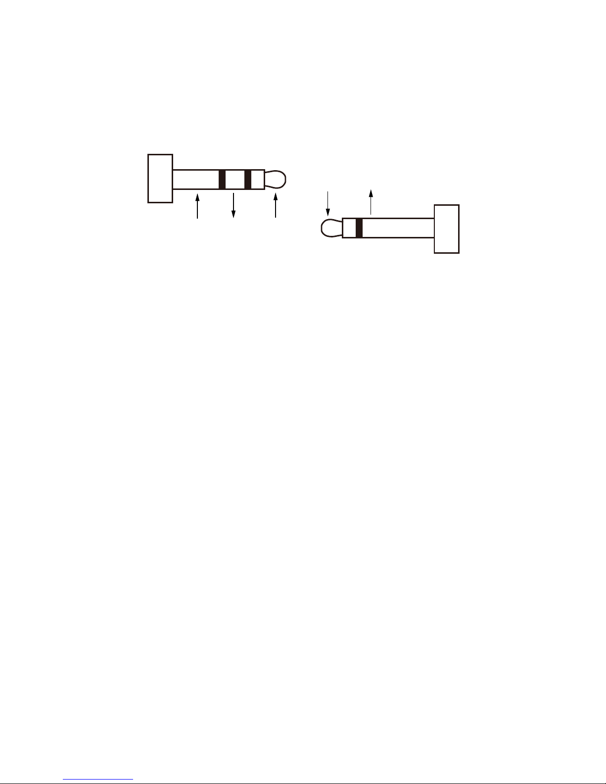
3.
How can I make the IR work with third party control devices?
Please make sure the third party device follows our pin denition as below:
IR Receiver
Gnd
IR signal
5V
IR Emitter
5V
IR signal
Page 22

21
1. The or
iginal serial number (specified by LINK) labeled on the product has
been removed, erased, replaced, defaced or is illegible.
2. The warranty has expired.
3. The defects
are caused by the fact
that the product is repaired,
dismantled
or
altered by anyone that is not from a LINK authorized service partner. The
defects are caused by the fact that the product is used or handled improperly,
roughly or not as instructed in the applicable User Guide.
4. The defects are caused by any force majeure including but not limited to
accidents, fire, earthquake, lightning, tsunami and war.
5. The service, configuration and gifts promised by salesman only but not covered
by normal contract.
6. LINK preserves the right for interpretation of these cases above and to make
changes to them at any time without notice.
Warranty Terms and Conditions
For
the following cases LINK s
hall charge for the service(s) claimed for
the products if the product is still remediable and the warranty card
becomes unenforceable or inapplicable.
Page 23
22
WWW.MSTRBRAND.COM
 Loading...