

Page 1
TECHNORAMA 612pc II
LINHOF PRÄZISIONS - SYSTEMTECHNIK GMBH
6x12 cm
MADE IN GERMANY
Page 2
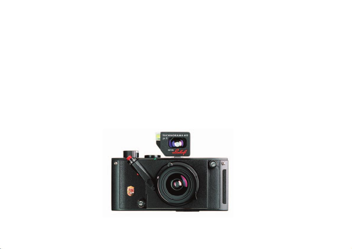
Zum Kauf ihrer Technorama 612 pc II beglückwünschen wir Sie. Mit
dieser Kamera haben Sie ein wertvolles Linhof Präzisionsgerät erworben, das Ihnen eine sachgemäße Behandlung durch stete Funktionsbereitschaft und lange Lebensdauer danken wird. Diese Bedienungsanleitung wird Ihnen beim Einsatz Ihrer Kamera eine Hilfe sein. Bitte
beachten Sie die folgenden Hinweise:
Die Technorama 612 pc II gestattet Panorama - Aufnahmen im Hochund Querformat mit dem Format 6x12 cm auf Rollfilm aus der Hand
in hervorragender Fachqualität.
Das besondere an dieser Kamera ist neben dem extremen Seitenverhältnis von 2 : 1, der eingebaute
Hochshift von 8 mm, der bei vielen
Motiven – z.B. Architektur, Industrie,
Kunstobjekten – stürzende Linien vermeiden hilft. Der stabile Vollmetallbody sorgt für exakte Filmplanlage
und Zuverlässigkeit auch bei Extrembedingungen unterwegs.
Die Technorama 612 pc II kann derzeit mit 5 Wechselobjektiven ausgestattet werden.
We would like to congratulate you on acquiring your new Linhof
Technorama 612 pc II. This is a sophisticated precision camera with
many exclusive features which should be treated as a fine optical
instrument and operated with proper care. The following instructions
will help you to use your Technorama correctly and to get excellent
results and many years of reliable service from your camera. The
Technorama 612 pc II allows professional hand-held panorama shots
in vertical or horizontal format on roll film using the extreme format
6x12 cm (2 1/4 x 5 in.). The main feature of this camera is the built-in
8 mm lens rise that creates the effect of a shift lens offering total per-
spective control both with high or low
camera angles. This feature avoids converging lines, especially with most
motifs like architecture, industry and
objects of art. The superbly finished, allmetal construction of the camera body
in Linhof precision quality guarantees
high-end photography even under extreme circumstances in off-road areas. The
Linhof Technorama 612 pc II is a system
camera with 5 interchangeable lenses.
2
BEDIENUNGSHINWEISE
LINHOF TECHNORAMA 612 PC II
OPERATING INSTRUCTIONS
LINHOF TECHNORAMA 612 PC II
Page 3

3
CONTENTSINHALT
1. FEATURES AND CONTROLS 5
2. FILM LOADING AND UNLOADING 7
3. CAMERA OPERATION 9
4. LENS CHANGE 11
5. LENSES 12
6. APERTURE AND DEPTH-OF-FIELD CONTROL 14
7. CENTER FILTER 15
8. THE PRECISION OPTICAL VIEWFINDER 16
9. SECTIONAL ENLARGEMENTS 18
10. HORIZONTAL PHOTOS FROM
AN ELEVATED VIEW-POINT 19
11. USE OF FLASH 20
12. TECHNICAL DATA 21
13. GENERAL COMMENTS 22
1. TECHNISCHE BESCHREIBUNG 5
2. FILMEINLEGEN UND FILMENTNAHME 7
3. BEDIENUNG DER KAMERA 9
4. OBJEKTIVWECHSEL 11
5. OBJEKTIVE 12
6. BLENDE UND SCHÄRFENTIEFE 14
7. CENTERFILTER 15
8. DIE OPTISCHEN SUCHER 16
9. AUSSCHNITT-VERGRÖSSERUNGEN 18
10. AUFNAHMEN AUS ERHÖHTEN
POSITIONEN 19
11. BLITZAUFNAHMEN 20
12. TECHNISCHE DATEN 21
13. HINWEISE 22
Page 4
4
1
2
3
16
15
1
18
17
15
19
5
4
9
9
10
6
7
9
20
16
17
18
19
12 11
8
8
L
R
Page 5

5
1. FEATURES AND CONTROLS
TECHNORAMA 612 PC II
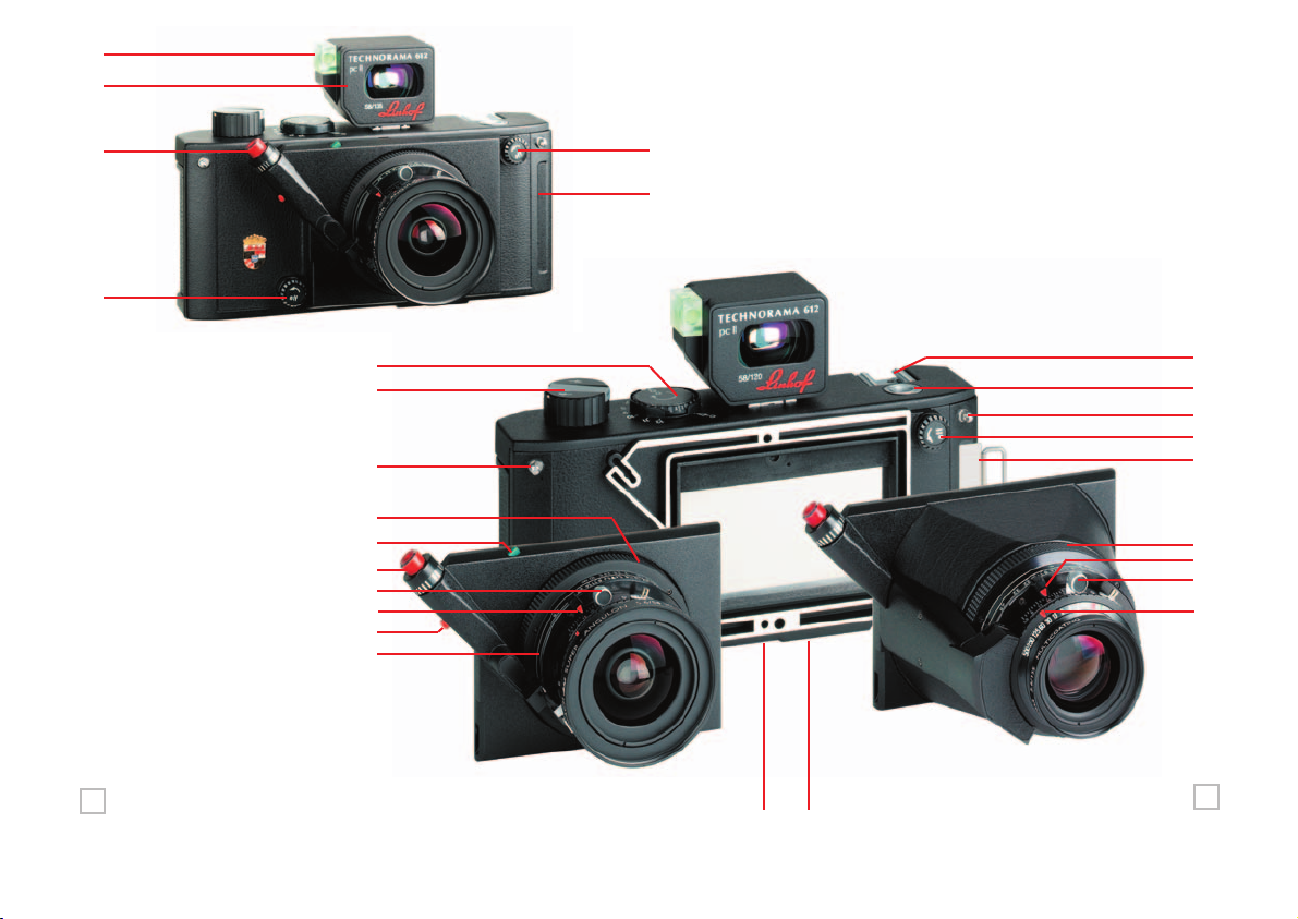
1 Gehäuseauslöser mit Gewinde für Drahtauslöser
2 Ausklappbarer Kurbeltrieb für Filmtransport, Filmtransportknopf
3 Zählscheibe mit Indexanzeige für Filmtransport
(6 Aufnahmen auf Rollfilm 120 und 12 Aufnahmen auf Rollfilm 220)
4 Abnehmbarer Präzisions-Leuchtrahmensucher für Wechselobjektive
5 In Sucher integrierte Wasserwaage (Kontrolle zur Senkrechtausrichtung der
Kamera im Quer- und Hochformat)
6 Zubehörschuh für Blitz, Belichtungsmesser etc.
7 Gesenktes 3/8” Stativgewinde, Oberseite Kamera
(Für Aufnahmen mit erhöhtem Standpunkt mit gedrehter Kamera)
8 Ösen für Umhängeriemen
9 Drehrändelschrauben, links-/rechts-drehend für Objektivwechsel
(Objektivwechsel nur bei vorne eingeschobenen Schieber möglich).
10 Einschubschacht für Lichtschutzschieber bei Objektivwechsel
(Normalposition des Schiebers: In der Rückwand)
11 Gesenktes 3/8” Stativgewinde, Unterseite Kamera
(In Abbildung verdeckt)
12 Versenkter Dreh-Schließbügel zum Öffnen/Schließen der
Kamerarückwand (In Abbildung verdeckt)
13 Blitz-Synchronisationsnippel, Verschluss-Vollsynchronisation bis 1/500s
14 Markierung für Entfernungseinstellung (Symbol: Dreieck)
15 Vollintegrierte Auslösesperre mit Anzeigestift gegen unbeabsichtigtes
Auslösen (Sichtbarer grüner Stift: Unverriegelter Auslöser, sichtbarer roter
Stift, unten: Verriegelter Auslöser)
16 Einstellring, links-rechtseitig drehbar für Entfernung
17 Einstellhebel, links-rechtsseitig schiebbar, für Blende
18 Präzisions-Verschluss-Spannhebel, mit Freilauf in eine Richtung ziehbar
19 Einstellring, links-rechtsseitig drehbar für Verschlusszeiten
20 Lichtschutzschieber, schiebbar und beidseitig in Einschubschacht geführt.
Normalposition des Schiebers: In der Rückwand.
1 Shutter release at camera body, including a cable release socket
2 Film advance/rewind knob with fold-out crank
3 Rotating frame counter with index for 6 photos on 120 and 12 photos
on 220 roll film
4 Detachable, precision bright line frame viewfinder for interchangeable
lenses.
5 Spirit level integrated into viewfinder (control of vertical orientation of
camera in either horizontal or vertical format)
6 Recessed accessory shoe for flash, exposure meter etc.
7 Lowered upper 3/8” tripod socket on top of camera (allows shooting from
an elevated point with a turned camera)
8 Eyelets for camera strap
9 Knurled locking knobs for lens panel change (changing of lenses only with
inserted dark slide)
10 Slot for inserting dark slide when changing lenses. Dark slide is
normally stored in the camera back.
11 Lowered lower 3/8” tripod socket at bottom of camera (cannot be seen
in illustration)
12 Recessed fold-down retaining lock for opening/locking detachable
camera back. To close, turn locking key firmly through approx. 180°.
13 X-sync nipple, shutter fully synchronised to 1/500 sec.
14 Index mark for focusing. Depth-of-field available is indicated by the pairs
off-stop figures at either side of the focusing index.
15 Safety lock to prevent unintentional shutter release. Shutter can be
released as long as the green end of the locking pin is visible. To lock, push
safety pin all the way down so that the red end becomes visible.
16 Easy-to-grip focusing ring, can be turned to the right or left for distance.
17 Aperture setting lever, can be pushed to the right or left.
18 Precision shutter cocking lever, in free move can be pulled in one direction.
19 Shutter speed selector ring, can be turned to the right or left for
different shutter speed.
20 Dark slide, can be pushed, has to be inserted on both sides into the shaft.
Normal storage position: in camera back.
1. TECHNISCHE BESCHREIBUNG
TECHNORAMA 612 PC II
Page 6
6
13
16
3
24
2
24
22
23
21
26
2
25
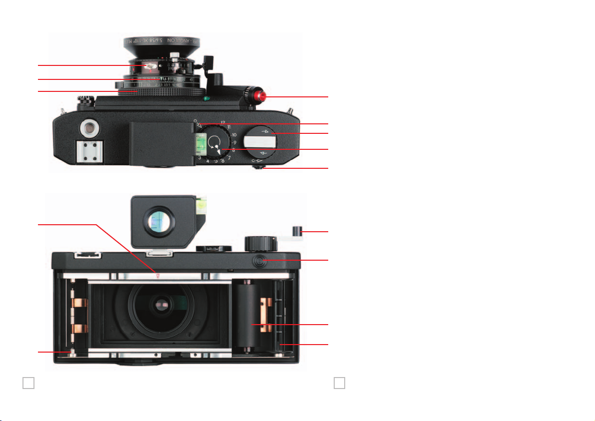
21 Spannfeder mit Spulenzentrierbolzen, nach außen bieg-
bar (Zur Aufnahme der unbelichteten Filmspule)
22 Spannfeder mit Spulenzentrierbolzen, nach außen
biegbar (Leerspule eingelegt)
23 Präzisions-Filmtransportwalze (Empfindliche Oberfläche)
24 Entriegelungstaste, rechtsseitig schiebbar
(Zur jeweiligen Transportfreigabe nach Auslösung,
Infomarke an Kameraoberseite)
25 Einstellmarke für Filmvorlauf (Bezugsposition Dreieck
für Filmvorlauf)
26 Gravierte Bezugsmarke für Filmaufgabe, Startposition
(Anfangsmarkierung am Filmschutzpapier sowie
Bezugsmarke liegen bei Filmaufgabe nebeneinander)
21 Film supply with leaf spring, can be bent outwards.
(To take the unexposed film spool)
22 Film take-up spool with leaf spring, can be bent out-
wards. (empty spool inserted).
23 Precision film transport roller (Sensitive surface)
24 Sliding film transport release knob with direction indica-
tor on top. Can be pulled to the right, allows transport
after shutter release.
25 Reference arrow on counterdisk to indicate the start posi-
tion of film travel
26 Reference mark for correct positioning of paper
leader, start position: start mark on film seal paper and
reference mark on camera are next to each other when
positioning new roll film.
1
14
L R
Page 7

2.1 Zum Öffnen der Kamera drehen des Dreh-Schließbügels (12) an der
Kameraunterseite in Position “OFF” und Abnehmen der Rückwand.
Leerspule rechts in Aufwickelseite durch drücken der Spannhalterung nach
unten einsetzen, dabei beachten, dass die Spule am Zentrierbolzen einwandfrei einrastet. Spule hilfsweise drehen.
2.2 Zum Einlegen eines unbelichteten Rollfilms: Filmspule in die Abwickelseite (21) einsetzen, Klebestreifen völlig entfernen und Film mit Filmschutzpapier über die Filmbühne ziehen, Lasche an Schutzpapier mittig in Leerspule einfädeln. Film durch Drehung des Kurbeltriebs (2) und vorheriger
Entriegelung (24) so weit aufspulen, bis die Anfangsmarkierung auf dem
Filmschutzpapier (Pfeil oder Dreieck) mit gravierter Markierung (26) nebeneinander liegen, dabei auf Planlage u. Faltenfreiheit des Films achten.
2.3 Einstellen der Filmandruckplatte für Rollfilm 120 oder 220 durch Andruck;
Verschieben und Einrasten dieser Platte auf rote bzw. grüne Signalmarke.
2.4 Die Kamerarückwand wieder ansetzen, parallel andrücken und durch
Drehung des Schließbügels (12) verriegeln.
2.5 Zählscheibe einstellen: Zählscheibe (3) bei gleichzeitiger Entriegelung von
(24) drehen. Bezugsmarkierungen “Dreiecke” in gegenüberliegende Position bringen. Zählscheibe rastet ein. Hilfsweise Scheibe geringfügig vorwärts-/rückwärts drehen.
2.6 Filmtransport, Aufnahmebereitschaft herstellen: Mit (24) entriegeln. Mit
(2) so lange drehen, bis Transportsperre wirksam wird. Das Zählwerk zeigt
Bild 1 an, die Kamera ist aufnahmebereit. Bei Verwendung von Rollfilm 120
stehen 6, bei Rollfilm 220 stehen 12 Aufnahmen zur Verfügung. Nach jeder
Aufnahme und vor dem Filmtransport mit (24) entriegeln.
2.7 Nach der letzten Aufnahme Entriegelungstaste (24) betätigen, gedrückt halten und den Film mit (2) restlos aufspulen, bis sich die Zählscheibe (3) nicht
mehr dreht. So ist gewährleistet, dass der exponierte Film vollkommen aufgespult ist. Danach Rückwand öffnen und den Film entnehmen.
2.1 To open the camera, turn the fold-down locking key (12) on the bottom of
the camera to the ‘off’ position and remove camera back. Insert empty film
spool in the take-up chamber on the right side by pressing the leaf spring
downwards. Make sure that the wind key engages properly. You might need
to wind the spool in order to position it correctly.
2.2 To load an unexposed film roll: place unexposed roll of film in the supply
chamber (21), remove tape seal completely and pull film including the film
covering paper until paper leader can be threaded into the middle of the
take-up spool. Pull release knob (24) in the direction of the arrow, if necessary, and advance film by turning the film advance knob (2) until the marks
of the backing paper (either arrow or triangles), are opposite the red reference triangle (26) on the camera housing. Make sure the film is in correct
position without any folds or creases.
2.3 Check film pressure plate for correct adjustment. For change-over from 120
to 220 film, push down and slide pressure plate as indicated by the arrow
and the red/green reference marks.
2.4 Attach camera back again and lock it by turning the fold-down key (12).
2.5 To adjust film counter: while pulling the release knob (24) rotate film coun-
ter disk (3) on top of camera until the two reference triangles face each other
and you can definitely notice the clicking noise. You might need to adjust by
carefully turning forwards or backwards.
2.6 Film transport, preparing for the first shot: Pull release knob (24). Turn
film transport knob (2) until it stops automatically and locks in position for
the first photo. Index on film counter disk now points to frame 1, camera is
ready for use. 6 photos are available with roll film 120, 12 photos when
using a roll film 220. After each shot and before winding the film to the next
stop, pull release knob (24).
2.7 After the final shot pull film release knob (24), keep it pulled and re-wind the
film completely with the film transport knob (2), until the counter disk (3)
does not move any more. This guarantees that the exposed film is fully
rewound onto the spool. Now you can open the camera and take out
the film.
2. FILMEINLEGEN UND
FILMENTNAHME
2. FILM LOADING AND
UNLOADING
7
Page 8
8
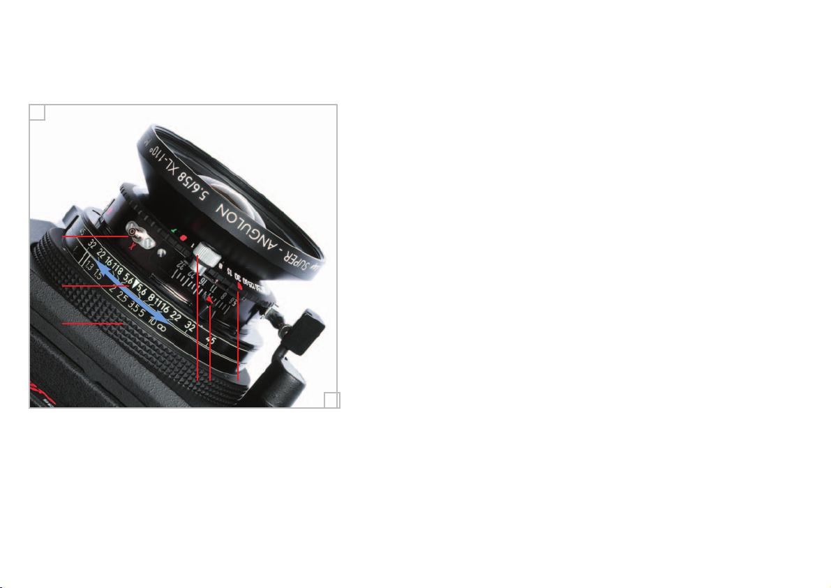
13 Blitz-Synchronisationsnippel,
Verschluss-Vollsynchronisation
bis 1/500 s
14 Markierung für Entfernungsein-
stellung (Symbol: Dreieck),
links und rechts davon Blendenpaare
zur Bestimmung der Schärfentiefe, je
nach Arbeitsblende
16 Entfernungs-Einstellring mit
Entfernungsskala in Meter oder Fuß,
die Dreiecksmarke (14) in der Mitte
des Schärfentieferings zeigt die effektive Entfernungseinstellung (optimale
Schärfe-Ebene).
Die Entfernungszahlen links des
Doppelstriches dienen zur Ermittlung
der Schärfentiefe im Nahbereich.
17 Blenden-Einstellhebel für
1/3-Blendeneinstellung; Blendenhebel
mit zusätzlicher Blendenskala.
18 Verschluss-Spannhebel: Vor jeder
Auslösung - objektivseitig betrachtet gegen den Uhrzeigersinn spannen.
19 Zeiten-Einstellring, B, T, 1 – 1/500 s
B-Einstellung: Verschluss offen,
solange Auslöser gedrückt ist.
T-Einstellung: Verschluss öffnet mit
erstem Auslösen, nochmaliges
Auslösen - Verschluss schließt.
13 X-sync nipple; shutter fully synchroni-
sed from B to 1/500 sec.
14 Index mark for focusing (symbol:
triangle). Depth-of-field available is
indicated by the pairs of f-stop
figures at either side of the focusing
index.
16 Helical focusing ring and distance
scale in metric or feet calibration.
Triangle (14) in the middle of the
depth-of-field scale indicates focusing
distance selected (the optimal depthof-field level).
The close-up distance shown left from
the double bar are for reference purposes only, indicating the depth-offield available at short distance.
17 Aperture scale in 1/3 increments.
Aperture setting lever with additional
aperture scale.
18 Shutter cocking lever. Anti-clockwise
cocking (when looking at it from the
lens side) necessary before each
release.
19 Shutter speed selector ring, B, T,
1 – 1/500 sec.
B-setting: shutter open as long as
release button is pressed.
T-setting: First press - shutter open,
second press – shutter closed.
13
17 1918
16
14
Die Schärfentiefeskala zwischen Entfernungs-Einstellring (16) und
Verschluss erstreckt sich zu beiden Seiten der Einstellmarke (14)
durch spiegelgleiche Blendenzahlen (Blauer Pfeil: Schärfentiefe bei
Blende 22 und Fokussierung auf 2,5 m)
The depth-of-field scale located between shutter and focusing ring
(16) shows symmetrically arranged pairs of f-stop figures.
L
R
Page 9

9
3.1 Fotografieren: Nach dem der Verschluss gespannt ist, Zeit, Blende (mit
externem Belichtungsmesser) und Entfernung (mit Hilfe des Schärfentieferings) eingestellt ist, kann fotografiert werden.
3.2 Auslösen: Der Auslösedruckpunkt liegt im unteren Drittel des Auslöseweges. Nach erfolgter Aufnahme Entriegelungstaste (24) betätigen und den
Film mit Kurbeltrieb (2) transportieren. Verschluss jeweils mit Spannhebel
(18) spannen. Die Kamera ist erneut aufnahmebereit.
3.3 Verwenden eines Drahtauslösers: Es kann der Linhof Drahtauslöser
022767 verwendet werden.
3.4 Auslösesperre: Die Auslösung ist nicht möglich, wenn
a) die Auslösesperre aktiviert ist (roter Stift 15 sichtbar) oder
b) der Verschluss nicht gespannt ist.
3.5 Film vollständig vor Entnahme aufspulen: Nach der sechsten und letzten
Aufnahme bei Verwendung von Film 120, bzw. der 12. Aufnahme bei Film
220, Entriegelungsknopf (24) in Pfeilrichtung betätigen, gedrückt halten und
den Film mit Kurbeltrieb (2) restlos aufspulen, bis sich die Zählscheibe (3)
nicht mehr dreht. So ist gewährleistet, dass der exponierte Film vollständig
aufgespult ist. Danach den Film entnehmen.
3.6 Doppelbelichtung: Für Doppelbelichtungen kann der Verschluss beliebig oft
gespannt und ausgelöst werden, ohne dabei den Film zu transportieren.
3.1 To take photos: After the shutter is cocked, shutter times, aperture settings
(external light meter) and focusing distance (with the help of the depth-offield indicator ring) are adjusted manually in the conventional way and you
can now take your photo.
3.2 Shutter release: the shutter release pressing point lies in the lower third of
the shutter release way. After each shot, pull release knob (24) and transport the film with the film transport knob (2) until it locks for the next frame.
Shutter is always cocked with button (18). The camera is ready for the next
shot.
3.3 To use a cable release: for best results, use original Linhof T-lock cable
release with extra long release pin (022767).
3.4 Shutter lock: the shutter cannot be released as long as the release lock is
engaged (red end of locking pin (15) is visible) or the shutter is not cocked.
3.5 Before taking film out of camera, make sure you have rewound the film
completely: After the sixth and final photo (with 120 film) or the twelfth
photo (with 220 film) pull film release knob (24) in direction of the arrow.
Keep it pulled and rewind film with the film transport knob (2) completely
until the film counter disk (3) does not move any more. This guarantees that
the exposed film is fully rewound onto the take-up spool.
3.6 Double/multiple exposures: Double and multiple exposures can be taken
by simply re-cocking the shutter as often as required without transporting
the film any further.
3. BEDIENUNG DER KAMERA 3. CAMERA OPERATION
Page 10

10
4.1 Objektivwechsel: Den Lichtschutzschieber (20) in den Einschubschacht
(10) einschieben, nur dadurch wird der Objektivwechsel mechanisch
ermöglicht, gleichzeitig der eingelegte Film vor Licht geschützt.
4.2 Position der Kamera zum Objektivwechsel: Kamera mit Objektiv nach oben
legen und Rändelschrauben (9) für die Objektivplatten-Verriegelung in
Pfeilrichtung lösen, Objektiv wechseln und beide Rändelknöpfe entgegen
der Pfeilrichtung verriegeln. Lichtschutzschieber wieder in die KameraRückseite einsetzen.
4.3 Perspektivkontrolle (pc): Der eingebaute Hochversatz der Objektive von 8
mm gestattet Querformataufnahmen höher positionierter Objekte ohne stürzende Linien. Die Kontrolle der Kamera mittels Wasserwaage im Sucher
ermöglicht die exakte Lotrecht-Ausrichtung. Für Aufnahmen mit betontem
Vordergrund und Aufsichten wird die Kamera gedreht.
Zu Aufnahmen mittels Stativ dient das integrierte Gewinde (7) bzw. (11) am
Kameragehäuse (vergl. auch Seite 19).
4.4 Achtung: Bei Aufnahmen von oben herab die Kamera niemals wie sonst
üblich neigen. Durch den eingebauten Hochversatz des Objektivs führt dies
zu extrem stürzenden Linien (Ausnahme: Dies ist gestalterisch gewünscht).
Bei Aufsichten daher Kamera stets umdrehen! So wirkt der Hochversatz als
Tiefversatz. Der Blick durch den Sucher überzeugt.
4.5 Die für den Einbau in die Technorama 612 pc II gefertigten Teile und
Objektive sind von hervorragender optischer Oualität. Beim Arbeiten sollte
nicht vergessen werden, dass diese Großformat-Fachobjektive erst abgeblendet ihre volle Leistung erreichen. Für maximale Schärfeleistung bis in
den Bildrand sollte im Bereich Blende 16 bis 32 gearbeitet werden. Bis
Blende 22 steigt die Gesamtleistung des Objektivs und damit die effektive
Abbildungsqualität.
4.1 Change of lens: Push dark slide (20) into slot (10) on camera front until it
reaches its end position. Due to the safety lock provided, the lens assembly
can only be removed if the dark slide is inserted behind the lens.
4.2 Positioning of camera: Hold or place the camera with the lens facing up,
open knurled lens panel locking knobs (9) – left turn, in direction of arrows.
Change lens and tighten both locking knobs – right turn. Pull and return
dark slide to its storage compartment in camera back.
4.3 Perspective control (pc): The built-in pre-shift acts as a lens rise (for architectural photos) or a lens drop, if camera is held upside down (for interior
photos) to provide images from a lower or higher viewpoint without converging lines. Using the precision viewfinder with its reflected spirit level,
the camera can be perfectly aligned in either position to obtain a correctly
composed image with straight vertical and horizontals by means of the reference cross. For images with pronounced forefront and top view the camera
is turned. For the use of the tripod there are two threads (7) and (11) - see
also page 19.
4.4 Attention: When taking pictures from an elevated viewpoint, do not tilt the
camera in the usual way. If you do so, be aware that the built-in pre-shift of
the lens leads to extremely converging lines in your photo. (Exception: if
that is a means of your wanted design). When taking top view pictures,
always turn the camera. This way the pre-shift works as a low-shift. A look
through the viewfinder will convince you.
4.5 The lenses are specially selected for the Technorama 612 pc II, featuring
state-of-the-art technology in optical and mechanical engineering. It should
be remembered, however, that those large format expert lenses achieve
their highest performance when stopped down. For maximum corner to
corner sharpness please use f/16 to f/32. Up to f-stop 22 the general performance of the lenses increases and therefore the optimum reproduction
quality.
4. OBJEKTIVWECHSEL 4. LENS CHANGE
Page 11
11
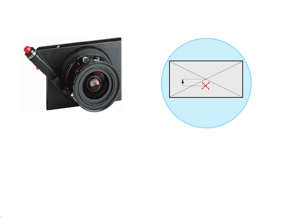
Bildkreis des Objektivs
Image circle
Aufnahmeformat / picture format 6x12 cm
Mittelpunkt des Bildkreises
real center of the image circle
Shift
Mittelpunkt des Aufnahmeformats
format center
8 mm
Perspektivkontrolle:
Die Grafik zeigt die Position des Aufnahmeformats im Bildkreis. Durch diesen
Festshift können z.B. Architekturaufnahmen korrekt ohne stürzende Linien wiedergegeben werden.
Perspective Control:
The illustration shows the position of the picture format within the image circle.
With this pre-shift e.g. architectural photos can be taken realistically without
converging verticals.
Technorama Super-Angulon XL 5,6/58 mm.
Objektiv in Copal-Verschluss und Einstellschnecke, auf Präzisions-Objektivplatte
mit integriertem Auslöser und Auslösesperre.
Lens in copal shutter and focus mount on precision lens panel with integrated
body release and safety lock to prevent unintentional shutter release.
Page 12
12
5. OBJEKTIVE
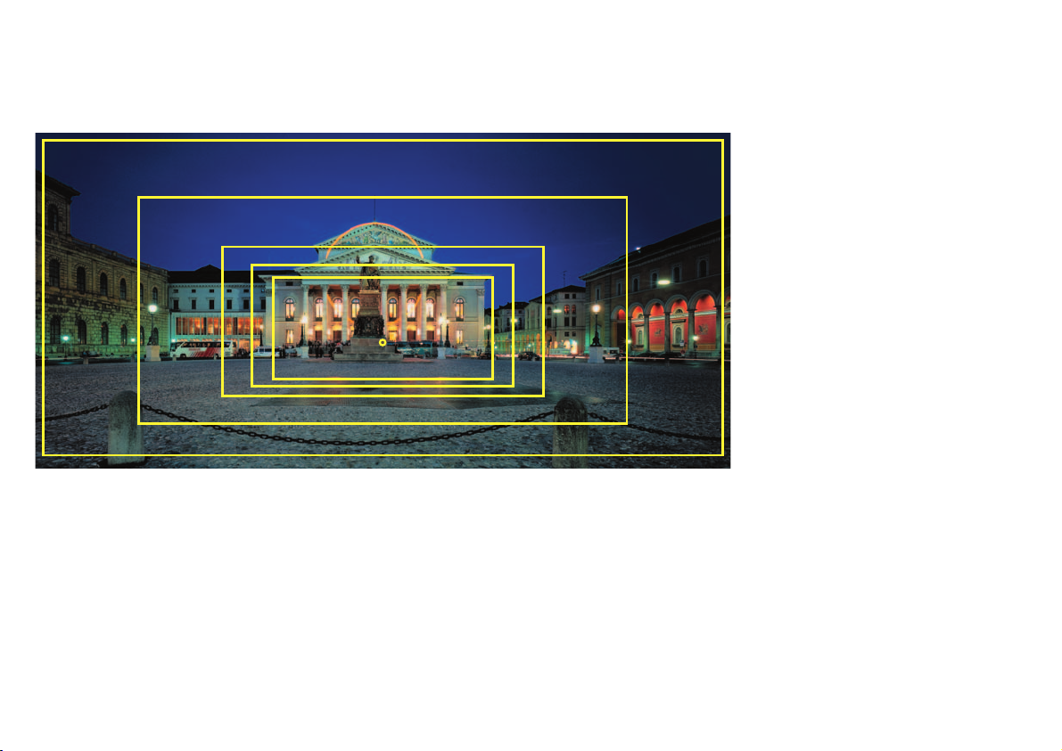
Die Rahmen zeigen die Wirkung der
einzelnen Objektiv-Brennweiten.
The focal effect of the picture section is
visible in this photo.
5.1 Für die Technorama 612 pc II sind derzeit 5 Wechselobjektive für
individuelle Bildgestaltung verfügbar. Neben dem bewährten Technorama Super-Angulon XL 5,6/58 ergänzen vier Objektive mit den
Brennweiten 80, 120, 150 und 180 mm das System. Alle Objektive
verfügen über einen besonders lang dimensionierten Schneckengang, der exaktes Fokussieren bis in den Nahbereich ermöglicht.
5.2 Die Spezialtuben der Objektive verfügen über einen integrierten
Schlagschutzbügel, der dem Auslösesystem bestmöglichen mecha-
nischen Schutz bietet. Darüber hinaus ermöglicht er der Kamera
einen optimalen Stand.
5.3 Die in den Linhof Technorama-Objektivkonstruktionen verwendeten
Schneider Objektive bieten höchste optische Qualität für verzeichnungsfreie Abbildungsleistungen: Die Horizontlinie bleibt bis in die
äußersten Ecken gerade.
5.4 Die eingesetzten Copal-Verschlüsse mit Belichtungszeiten von bis
zu einer 1/500 s gestatten das Fotografieren aus der Hand.
58 mm
80 mm
120 mm
150 mm
180 mm
opt. Achse
Page 13
13
5. LENSES
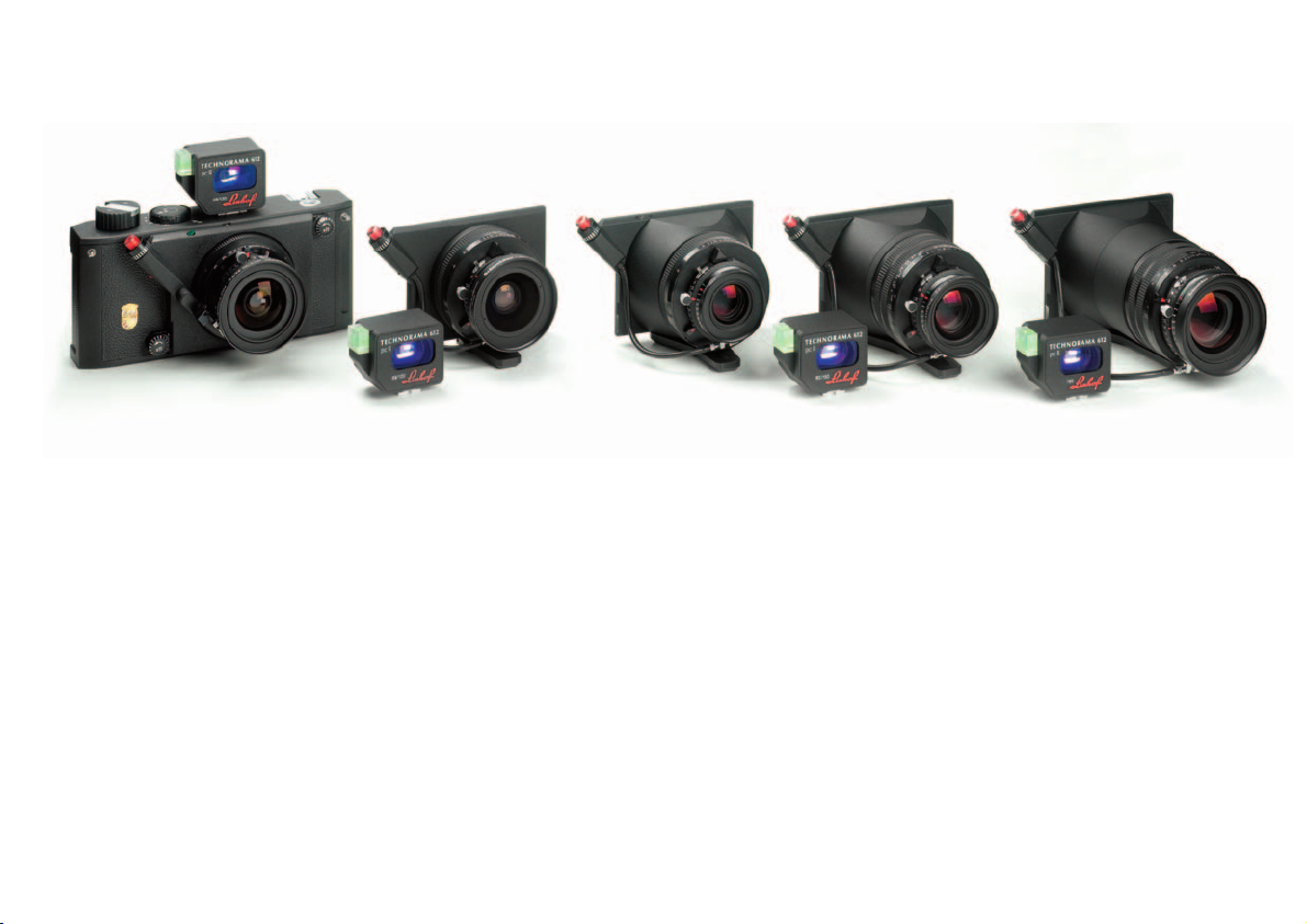
Technorama 612
Apo-Symmar L 5,6 / 180
TECHNORAMA 612 pc II
mit Super-Angulon XL 5,6 / 58
Technorama 612
Apo-Symmar L 5,6 / 120
Technorama 612
Apo-Symmar L 5,6 / 150
Technorama 612
Super-Symmar XL 4,5 / 80 Asph.
5.1 5 interchangeable lenses with individual angles of view are now
available. In addition to the proven wide-angle lens Technorama
Super Angulon XL 5,6/58 mm four high performance lenses are
offered: 80 mm, 120 mm, 150 mm and 180 mm focal length. All lenses are equipped with especially long dimensioned helical mounts
for precise focusing even at close-range.
5.2 The integrated anti-shock supports of the tubes provide an optimum mechanical protection for the shutter release system facilitating the perfect positioning of the camera.
5.3 Technorama lenses made by Schneider/Bad Kreuznach and specially selected by Linhof are totally distortion-free of optimum quality.
5.4 Thanks to shutter speeds from 1 s to 1/500 s the Technorama permits hand-held photography.
Page 14

14
6.1 Blendeneinstellung: Die Blende ist entsprechend der Skala im Bereich von
Blende 5,6 bis Blende 32 (58 mm) bzw. 64 in Drittelwerten einstellbar. Die
Arbeitsblende soll zwischen Blende 16 und 32 liegen, da bei größeren
Blenden (8 oder 11) die volle Schärfeleistung am Bildrand nicht erreicht
wird. Über Blende 22 hinaus tritt keine Verbesserung der Bildqualität ein. Es
nimmt zwar die Schärfentiefe noch zu (siehe Schärfentiefering), aber bei
extrem kleinen Blenden (45) können bereits Kontrastverluste und Schärfeminderung durch Beugung auftreten.
6.2 Schärfentiefe festlegen: Die Schärfentiefe bezeichnet den Bereich noch
ausreichender, aber kontinuierlich abnehmender Schärfe im Vorder- und
Hintergrund bei normaler Bildbetrachtung. Der Schärfentiefering zwischen
Entfernungs-Skala und Verschluss ermöglicht die Bestimmung der Schärfentiefe. Optimale Schärfe wird grundsätzlich in der Ebene der exakten Entfernungseinstellung (14) erreicht. Die Blendenpaare auf beiden Seiten der
Skala begrenzen den jeweiligen Schärfentiefebereich.
Dabei gilt, je kleiner die Blende, desto größer die Schärfentiefe (Blende 22
gilt dabei als kleiner als z.B. Blende 16 oder 11).
Beispiel: Bei 58 mm Objektiv, Blende 22 und Einstellung auf 2,5 m:
Schärfentiefebereich von 1,3 m bis unendlich (blauer Pfeil in Abbildung
Seite 8).
6.3 Schärfentiefe im Nahbereich: Die Entfernungsskala reicht über den kürzesten Einstellbereich hinaus. Der Bereich links neben dem Doppelstrich ist
also nicht bis auf die Einstellmarke beziehbar, er dient lediglich der
Schärfentiefedefinition im Nahbereich bei entsprechender Abblendung.
6.1 Adjusting of f-stop: The aperture scales covers a range from f/5.6 to f/32
(58 mm) or f/64 respectively in 1/3 increments. For optimum edge to edge
sharpness, the aperture setting of between f/16 and f/32 is recommended.
With higher aperture openings (like 8 or 11) the sharpness at the edges cannot be achieved. Larger openings than f-stop 22 do not produce better
results. Extremely small openings, while increasing the depth-of-field, may
degrade the image on account of diffraction.
6.2 Depth-of-field: The depth-of-field describes the area where there is still
enough, but continuously diminishing sharpness in the front and the background of the photo. The depth-of-field ring (14) between distance scale
and shutter allows convenient depth-of-field calculation with any given lens
opening. Optimum sharpness is basically obtained in the level of an exact
distance setting (14). The pair of f-stops figures on both sides of the focusing index marks the respective depth-of-field area: the smaller the aperture, the more the depth-of-field is prolonged (f-stop 22 is acknowledged to
be smaller than f-stop 16 or 11).
Example: For 58 mm lens – an aperture of f/22 and camera focus to 2.5 m
(8.2 ft): a sharp image will be produced from 1.3 m (4.3 ft) to infinity (blue
arrow in illustration on page 8).
6.3 Depth-of-field in close-up distances: Although a minimum distance is
indicated, the focusing scale extends further down. The area left of the
double bar is not to be applied to the focusing mark. It is only used for
depth-of-field definition in the close-up area when lens is stopped down
accordingly.
6. BLENDE UND SCHÄRFENTIEFE 6. APERTURE AND
DEPTH-OF-FIELD CONTROL
Page 15
15
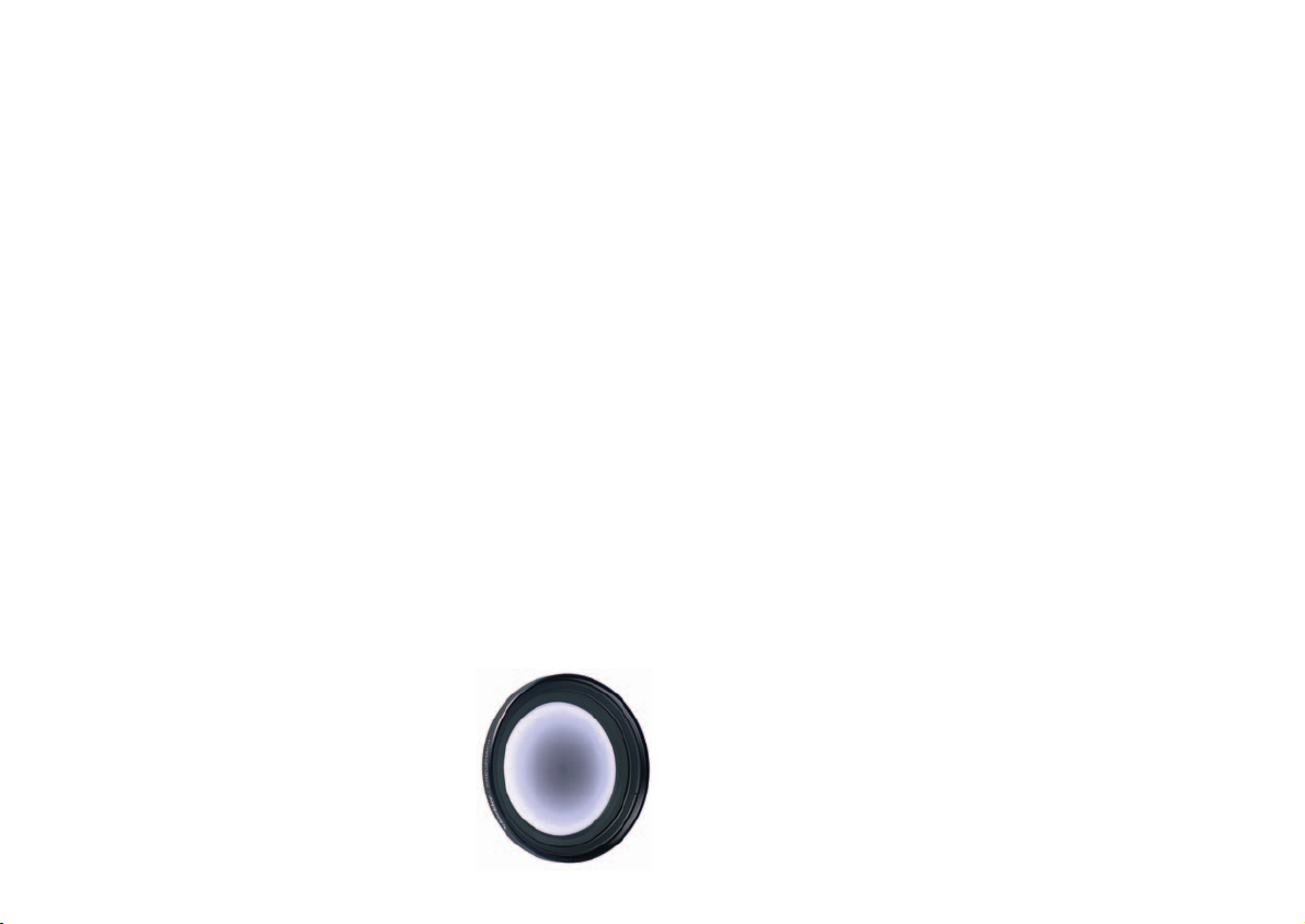
7.1 Einsatz des Centerfilters: Super-Weitwinkelobjektive haben physikalisch
bedingt einen natürlichen Randlichtabfall im Bildkreis und damit auch zu
den Bildecken hin. Um diesem Helligkeitsabfall entgegenzuwirken, wurden
für die Weitwinkelobjektive konzentrische Grauverlauffilter entwickelt, die
eine von innen nach außen zunehmende Lichtdurchlässigkeit aufweisen.
Dabei wurde auf den vollständigen Ausgleich des Randlichtabfalls der
Objektive verzichtet, um die dadurch erforderliche Verlängerung der
Belichtungszeiten nicht überproportional ansteigen zu lassen. Wenn mit
Centerfiltern gearbeitet wird, sollte das Objektiv um ein bis zwei Blendenstufen abgeblendet werden, da erst dann die ausgleichende Wirkung des
Centerfilters voll zur Geltung kommt.
Bei Nachtaufnahmen kann auf den Centerfilter u.U. verzichtet werden.
7.2 Zusätzliche Filter: Diese sollten in das Einschraubgewinde des Centerfilters
geschraubt werden, da sonst die Wirkung des Centerfilters ungünstig verändert wird.
7.3 Auf das Super-Angulon XL 5,6/58 wurde das Präzisionsfilter, Code 022282,
abgestimmt. Der Verlängerungsfaktor beim Einsatz dieses Filters beträgt ca.
1,5 mal, also 1 1/3 bis 1 2/3 Blenden je nach Motiv.
7.4 Bei Verwendung von Color- oder SW-Negativmaterial kann wegen des größeren Belichtungsspielraums und der Kompensationsmöglichkeiten im
Positiv auf das Centerfilter in den meisten Fällen verzichtet werden. Oftmals
ist eine leichte Abdunkelung an den Formatecken zur Steigerung der Bildwirkung erwünscht.
7.5 Achtung: Den Centerfilter beim Einschrauben
nicht zu fest anziehen, damit beim Herausschrauben Objektivverbindungen nicht gelöst
werden.
7.1 Use of the Center Filter: Super-wide-angle lenses have a natural fall-off of
illumination towards the corners which is caused physically. In order to
compensate this loss in brightness, concentric graduated grey filter have
been
designed for the wide-angle lenses. These filters have a transparency which
increases gradually from the center to the edges. To avoid too long exposures times and with consideration of the exposure latitude of the film emulsions, the vignetting of the lenses has not been fully compensated. For
maximum results and definition when using Center filter, it is necessary to
stop down the lens by one to two full stops, since only then the maximum
compensating effect of the Center filter can be achieved.
7.2 Additional filters: Additionally used filters should be screwed in the thread
of the Center filter, since otherwise the effect of the Center filter will be changed negatively.
7.3 For the lens Super Angulon XL 5.6/58 we recommend the center filter, code
number 022282. This Center filter requires an approximate 3 x exposure
increase which is equivalent to opening the lens by 1 1/3 or 1 2/3 stops
(depending on the motif).
7.4 As colour negative and black-and-white films have a wider exposure latitude and allow to correct the image in the printing process, you can do
without a center filter in most cases and still obtain a well-balanced print. In
many instances, slightly darker corners even help to enhance the image and
to dramatise the pictorial content of a picture.
7.5. Attention: The center filter should not be screwed in too tightly to avoid
inadvertent unscrewing of the front lens section when removing the filter.
7. CENTERFILTER
7. CENTER FILTER
Centertfilter gleichen den Helligkeitsabfall zum
Rand des Bildkreises aus.
Center filter to reduce the light fall-off
at the edges.
Page 16

16
8.1 Hochwertige Sucher: Für die Technorama 612 pc II stehen folgende Sucher
zur Verfügung: Für die Brennweiten 58 und 120 mm sowie 80 und 150 je ein
kombinierter Sucher, für Brennweite 180mm ein separater Sucher.
Die Verbindung mit der Kamera erfolgt über den mittleren Sucherschuh.
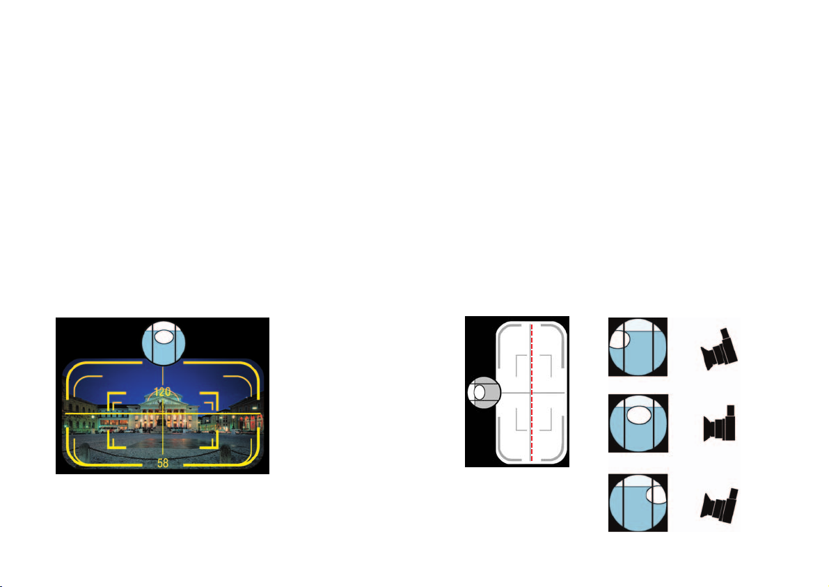
8.2 Leuchtrahmen im Sucher: Der eingespiegelte Leuchtrahmen zeigt den
exakten Bildausschnitt mit einer Sicherheitsreserve von ca. 10% an, das
Sucherbild zeigt also etwas weniger als später auf dem Film zu sehen ist.
Im Sucher eingespiegelt: Leuchtrahmen für die entsprechenden Objektive
zur Bildausschnittsbestimmung, Parallaxenkorrektur für den Nahbereich,
Wasserwaage und Referenzkreuz zur horizontalen und vertikalen Ausrichtung.
8.3 Motivbetrachtung: Wegen des großen Bildwinkels wurde im Sucher die
optisch bedingte, tonnenförmige Verzeichnung beibehalten. In der Abbildung auf dem Film werden die waagerechten und senkrechten Linien
ohne Krümmung verzeichnungsfrei wiedergegeben.
8.4 Eingespiegelte Wasserwaage: Die Wasserwaage, die auch von außen ablesbar ist, ermöglicht und kontrolliert die Vertikalausrichtung der Kamera
(Neigung nach oben oder unten) und zeigt somit jeweils die Lotrechte der
Filmebene an. Auf diese Weise werden stürzende Linien sowohl im Querals auch im Hochformat vermieden.
8.5 Ausrichtung der Kamera: Das eingespiegelte Referenzkreuz erlaubt die
waagerechte Ausrichtung der Kamera (Horizont waagerecht, lotrechte
Objektlinien senkrecht) und ermöglicht außerdem die parallele Ausrichtung
der Kamera zur Objektebene (z.B. Hausfassade). Dies geschieht folgendermaßen: Es ist die vom eigenen Standpunkt senkrecht auf das Objekt stoßende (gedachte) Linie zu suchen; Bodenlinien können dabei hilfreich sein.
Dort, wo die Linie das Objekt trifft, ist die Senkrechte des Sucherkreuzes zu
positionieren. So wird das Objekt ohne Fluchtlinien abgebildet. Diese
Methode kann für horizontale wie auch vertikale Motive angewandt werden.
8.1 High quality viewfinders: The crystal clear optical viewfinders (Albada) with
brightline finder frames for 58/120 mm, 80/150 mm and 180 mm lenses
showing the built-in vertical shift is part of the system camera
Linhof Technorama 612 pc II. The optical viewfinder is attached to the
camera using the accessory shoe in the center of the camera body.
8.2 Brightline frame in viewfinder: Precise framing of the subject is accomplished by the bright line frames. The viewfinder shows the image area with
a safety margin of approximately 10%, so the picture covers slightly more
than can be seen in the viewfinder.
Visible in the finder: spirit level and brightline frames for picture sections,
parallax corrections for close-range photos and reference cross for horizontal and vertical orientation (Illustration a).
8.3 Looking at the motif: On account of the extremely large viewing angle, the
viewfinder shows a slight amount of barrel distortion which, for technical
reasons, is not fully eliminated. The distortion is apparent in the finder only
and does not affect the actual image. Both lenses are totally distortion-free
and, naturally, all horizontals and verticals are reproduced as straight lines
on film.
8.4 Reflected spirit level: the reflected spirit level, visible in the finder, controls
the vertical orientation of the film plane not only with the camera in the conventional horizontal position, but in the vertical mode as well. To avoid converging lines do not tilt the camera, always check the spirit level to be sure,
that the camera is properly aligned.
8.5 Alignment of the camera: Horizontal alignment (lateral levelling) is controlled by the reflected reference cross which shows if the camera is tilted to
the left or right side. A convenient method to control parallelism between
film plane and main subject plane (front of the building, for instance) is to
project an imaginary line from the camera position to the object which
meets the main object plane at a 90° angle. Lines on the floor can be very
helpful for this. The point where the projected line meets the object line
should be positioned in the center of the reference cross. This method
works with both horizontal and vertical subjects.
8. DIE OPTISCHEN SUCHER
8. THE PRECISION OPTICAL
VIEWFINDERS
Page 17
17
8.6 Vertical photos: When taking vertical pictures of symmetrical objects
(church interiors, for instance) proceed as follows to compensate for the
lens displacement incorporated for horizontal images: If also the horizontal
lines should be kept parallel (for instance the floor lines or back wall of the
rooms) disregard the vertical center line and frame your subject off center
in such a way that the subject’s center line coincides with the imaginary
dotted line as shown in illustration b.
8.7 Finding a motif without camera: The viewfinder can also be used separate-
ly for easy determining the selected photo area.
8.6 Hochaufnahmen: Bei Hochaufnahmen symmetrischer Objekte, z.B. der
Innenraum einer Kirche, ist der für die Queraufnahme eingebaute Hochversatz folgendermaßen zu berücksichtigen: Unter der Vorgabe, dass auch
die horizontalen Linien parallel bleiben (Bodenlinien, Rückwand des Raumes
etc.), darf die Objekt-Mittelachse nicht in die Vertikallinie des Referenzkreuzes fallen, sondern muss im Sucher derart verlaufen, wie in der
Illustration b durch die rote gestrichelte Linie markiert ist.
8.7 Motivsuche ohne Kamera: Der von der Kamera abgenommene Sucher kann
zur Motivsuche und Motivbetrachtung im Vorfeld der Aufnahme verwendet
werden.
Die eingespiegelte
Wasserwaa
ge zeigt die
lotrechte
Kameraposi
tion an.
Reflected
spirit level
shows the
orientation
of the
camera.
Illustration b
Illustration a
Im Sucher eingespiegelt:
Leuchtrahmen für die entsprechenden Objektive zur Bildausschnittsbestimmung,Parallaxenkorrektur für den Nahbereich, Wasserwaage und
Referenzkreuz zur horizontalen
und vertikalen Ausrichtung.
Visible in the finder:
spirit level and brightline frames for picture sections, parallax corrections for close-range
photos and reference cross for
horizontal and vertical orien
tation.
Illustration c
Page 18
18
9. AUSSCHNITTVERGRÖSSERUNGEN
9. SECTIONAL ENLARGEMENTS
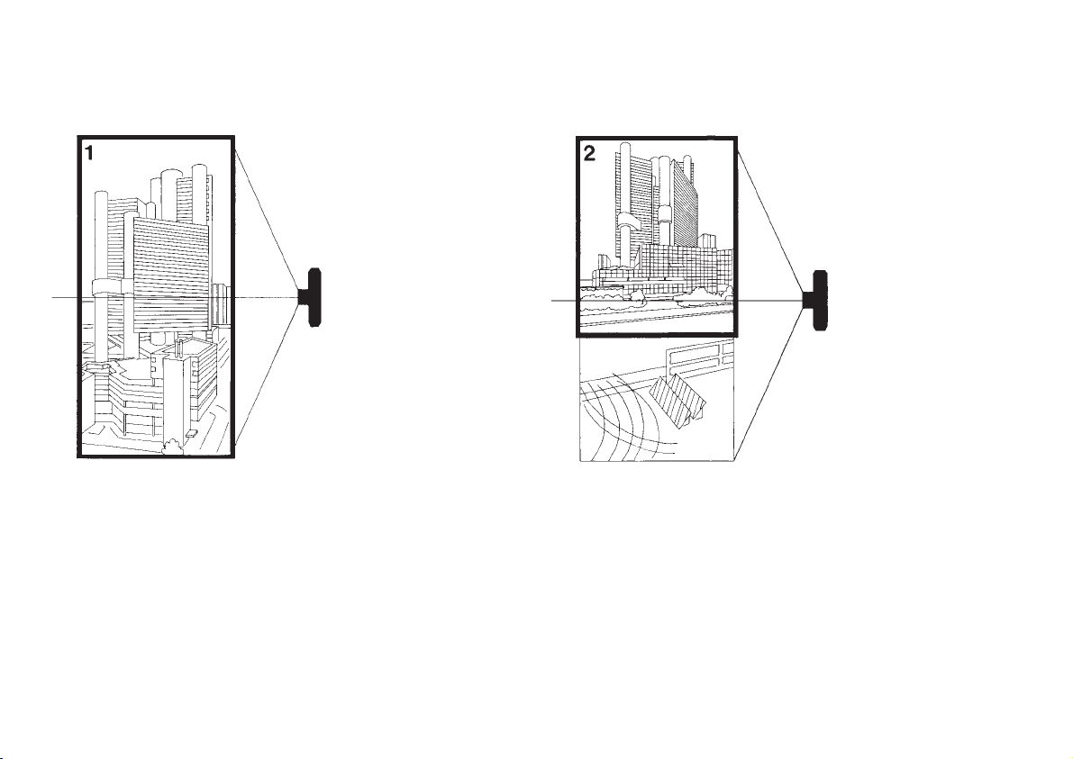
9.1 Das Spezialformat 6x 12 mit seinem 1 : 2 – Verhältnis eignet sich besonders für Architektur, Landschaft, lnterieurs, Technik, Kunst – hoch
und quer. Bei entsprechender Standpunktwahl, das Bildbeispiel (1)
zeigt eine Aufnahme aus einem Nachbarhaus, kann das Gesamtformat
bildwirksam genutzt werden.
9.2 Ist der Fotograf jedoch an den Bodenstandpunkt gebunden, kann er mit
der Technorama 612 pc II auch extrem hohe (oder tiefer gelegene) Objekte ohne stürzende Linien abbilden: Lotrechte Kamerahaltung durch
Wasserwaage feststellen, Objekt im Sucher platzieren; bei Auswertung
den bildwirksamen Ausschnitt verwenden (Bildbeispiel 2).
9.1 The elongated 6x12 cm format with its 1 : 2 aspect ration is eminently suitable for dramatic effects in technical and artistic photography, it is ideal for
architecture, scenic, interiors and equally adaptable to both horizontal and
vertical subjects. By choosing the proper viewpoint – the illustration shows
a photo taken from a neighbouring building – the total film format can be
used for the composition of the photo (1).
9.2 If the photographer, however, has to shoot from ground level, the
Technorama 612 pc II still allows him to record even extremely high (or
respectively low situated) subjects without converging lines: simply check
the vertical alignment of the film plane with the aid of the reflected spirit
level and frame the subject according to finder delineation and reference
cross. Print only the appropriate selection of the image, cropping any
unwanted foreground matter (2).
Kamera in
Bodennähe
Camera on
ground level
Erhöhter
Kamerastandpunkt
Camera on an
elevated viewpoint
Page 19
19
10. AUFNAHMEN AUS ERHÖHTEN
POSITIONEN
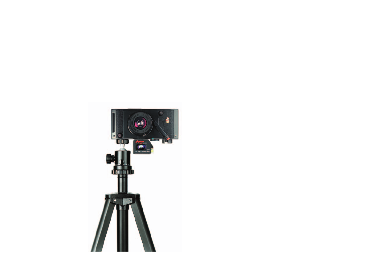
10.1 Queraufnahmen aus erhöhter Position: Queraufnahmen aus erhöhter Po-
sition (Aufsichten) erfordern ein Umdrehen der Kamera, so dass der Hochversatz des Objektivs zu einer Tiefverstellung wird; das Stativgewinde (7)
auf der Kameraoberseite dient dieser Anwendung.
Eine solche Kameraposition ermöglicht z.B. Innenaufnahmen ohne stürzende Linien von einer Leiter aus.
10.1 Horizontal photos from an elevated view-point: those photos can be taken
without converging lines by turning the camera upside down – the built-in
lens rise now becomes a lens drop. To do this, the camera is equipped with
a second tripod socket on the top of the camera housing (7). The spirit level
works also in the inverted position.
Achtung: Bei erhöhtem Standpunkt also
Kamera unbedingt umdrehen wie die
Abbildung zeigt. Wird die Kamera in
gewohnter Weise nach unten geneigt,
entstehen extrem stürzende Linien.
Attention: When shooting from an elevated position, always turn camera upside
down as shown on the illustration. Only
by doing this you enable the camera to
use the built-in lens rise as a lens drop. If
you do not turn the camera, extremely
converging lines will be the result!
10. HORIZONTAL PHOTOS FROM
AN ELEVATED VIEW-POINT
Page 20

20
11. BLITZAUFNAHMEN 11. USE OF FLASH
11.1 Die Verschlüsse der Objektive gestatten eine Blitzsynchronisation von B bis
1/500 s.
11.2 Beim Einsatz von aufsteckbaren Blitzgeräten mit Mittenkontakt im linken
Aufsteckschuh muss ein Verbindungskabel vom Blitz zur X-Synchronisation
(13) des Verschlusses verwendet werden.
11.3 Beim Arbeiten mit dem Super-Angulon XL 5,6/58 empfehlen sich für eine
gleichmäßige Ausleuchtung zwei Blitzgeräte (auf jeder Seite der Kamera ein
Blitzgerät) unter Verwendung einer geeigneten Halteschiene.
11.1 The shutter is fully synchronised from B to 1/500 sec.
11.2 The left accessory shoe can be used to mount a compact flash unit. As this
accessory shoe is not equipped with a flash contact, connect flash gun with
the X-sync nipple (13) on the shutter by means of a suitable flash cord.
11.3 When working with the Super Angulon XL 5.6/58, the use of 2 flash units,
mounted on a suitable flash bracket, is recommended on account of the
wide angle of view. To avoid hot spot in the center, the flash guns should be
angled outward.
Page 21

21
Länge x Breite x Höhe Gewicht
Length x Depth x Height Weight
000099 Technorama 612 pc II (6x12 cm) Technorama 612 pc II (6x12 cm)
Gehäuse ohne Sucher, ohne Objektiv, mit Umhängeriemen camera body without lens and viewfinder, w. camera strap 220 x 50 x 110 mm 1200 g
000894 Technorama Super Angulon XL 5,6 / 58 mm Technorama Super Angulon XL 5,6 / 58 mm 70 x 152 x 105 mm 650 g
T, B, 1 s - 1/500s, Blende 5,6 - 32, T, B, 1 s - 1/500s, aperture range 5,6 - 32,
effektiver Bildwinkel 92°, kürzeste Einstellentfernung 1,2 m effective angle of view 92°, shortest distance 1,2 m
000775 Technorama Super-Symmar Aspheric XL 4,5 / 80 mm Technorama Super-Symmar Aspheric XL 4,5 / 80 mm 87 x 152 x 105 mm 718 g
T, B, 1 s - 1/500s, Blende 4,5 - 45, effektiver Bildwinkel 74°, T, B, 1 s - 1/500 s, aperture range 4,5 - 45, eff.angle of view 74°
kürzeste Einstellentfernung 0,98 m, Filtergewinde M 67 x 0,75 shortest distance 0,98 m, filter mount M 67 x 0,75
000776 Technorama Apo-Symmar L 5,6 / 120 mm Technorama Apo-Symmar L 5,6 / 120 mm 106 x 152 x 105 mm 807 g
T, B, 1 s - 1/500s, Blende 5,6 - 64, effektiver Bildwinkel 52°, T, B, 1 s - 1/500 s, aperture range 5,6 - 64, eff.angle of view 52°
kürzeste Einstellentfernung 2,1 m, Filtergewinde M 52 x 0,75 shortest distance 2,1 m, filter mount M 52 x 0,75
000777 Technorama Apo-Symmar L 5,6 / 150 mm Technorama Apo-Symmar L 5,6 / 150 mm 133 x 152 x 105 mm 943 g
T, B, 1 s - 1/500s, Blende 5,6 - 64, effektiver Bildwinkel 44°, T, B, 1 s - 1/500 s, aperture range 5,6 - 64, eff.angle of view 44°
kürzeste Einstellentfernung 1,58 m, Filtergewinde M 58 x 0,75 shortest distance 1,58 m, filter mount M 58 x 0,75
000778 Technorama Apo-Symmar L 5,6 / 180 mm Technorama Apo-Symmar L 5,6 / 180 mm 172 x 152 x 105 mm 1195 g
T, B, 1 s - 1/400s, Blende 5,6 - 64, effektiver Bildwinkel 37°, T, B, 1 s - 1/400 s, aperture range 5,6 - 64, eff.angle of view 37°
kürzeste Einstellentfernung 2,15 m, Filtergewinde M 72 x 0,75 shortest distance 2,15 m, filter mount M 72 x 0,75
001310 Technorama-Sucher für f 58 / 120 Technorama Viewfinder for f 58 / 120 37 x 65 x 52 mm 100 g
mit eingespiegelter Wasserwaage, Referenzkreuz und with bright line frames and reflected spirit level
Parallaxenausgleich and parallax correction
001311 Technorama-Sucher für f 80 / 150 Technorama Viewfinder for f 80 / 150 37 x 65 x 52 mm 100 g
mit eingespiegelter Wasserwaage, Referenzkreuz und with bright line frames and reflected spirit level
Parallaxenausgleich and parallax correction
001312 Technorama-Sucher für f 180 Technorama Viewfinder for f 180 37 x 65 x 52 mm 100 g
mit eingespiegelter Wasserwaage, Referenzkreuz und with bright line frames and reflected spirit level
Parallaxenausgleich and parallax correction
022282 Centerfilter für f 58, Filtergewinde M 67 x 0,75 / M 86 x 1 Center filter for f 58 with dual threading for 90 mm 113 g
überbaut M 67 x 0,75 / M 86 x 1
022471 Alu-Koffer Aluminium case 430 x 185 x 275 mm 3665 g
für Kamera mit 4 Objektiven, Sucher, Filter und Filmen for body with four lenses, viewfinder, filter and films
12. TECHNISCHE DATEN / TECHNICAL DATA
Page 22
TECHNISCHE ÄNDERUNGEN VORBEHALTEN SPECIFICATIONS SUBJECT TO CHANGE PRINTED IN GERMANY 025059/04.07/ DE
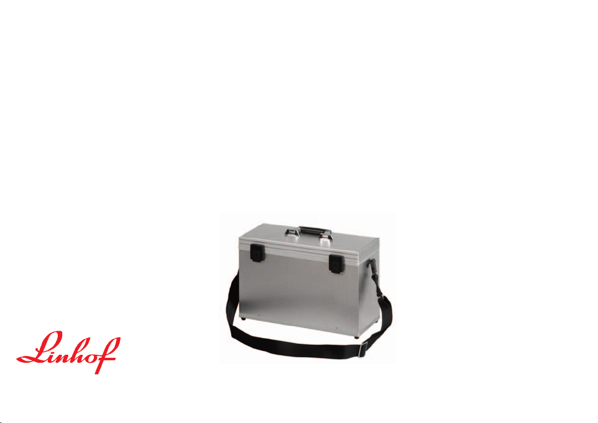
Alu-Koffer 022471
Zum Schutz und Transport der Kamera empfehlen wir den stabilen Linhof SpezialKoffer (022471). Er nimmt die 612 pc II mit angesetztem Objektiv und 3 weitere
Wechselobjektive auf.
Pflege der Präzisions-Filmtransportwalze
Die Oberfläche der Gummi-Transportwalzen wird nach längerem Gebrauch glänzend. Es empfiehlt sich daher, die Gummiwalze von Zeit zu Zeit mit einem Tuch und
etwas Extraktionsbenzin (fettfreies Reinigungsbenzin: Isohexan) zu reinigen, so
dass sie ihre Griffigkeit behält.
Camera Aluminium Case 022471
For added protection during transport we recommend to keep the camera always
in its custom-designed sturdy aluminium case (022471) accepting a camera with
four lenses and finders.
Maintenance of the rubber transport roller
After prolonged use, the surface of the rubber transport rollers may become shiny
and slightly slippery. It is recommended to clean these rollers from time to time
with a soft cloth and some cleansing solvent (Isohexan).
13. HINWEISE 13. GENERAL COMMENTS
Alu-Koffer für Kamera mit 4
Objektiven, Sucher, Filter und Filmen
Aluminium case for camera, 4
lenses, viewfinder, filter und
film rolls
LINHOF PRÄZISIONS - SYSTEMTECHNIK GMBH | RUPERT - MAYER - STRASSE 45 | 81379 MÜNCHEN /GERMANY
TEL. +49.89.72492-0 | FAX +49.89.72492-250 | [email protected] | www.linhof.de
 Loading...