

Page 1
M A D E I N G E R M A N Y
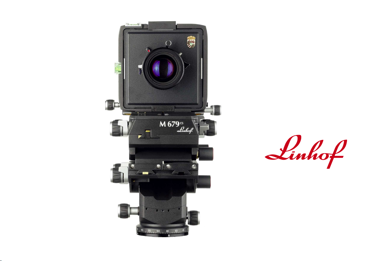
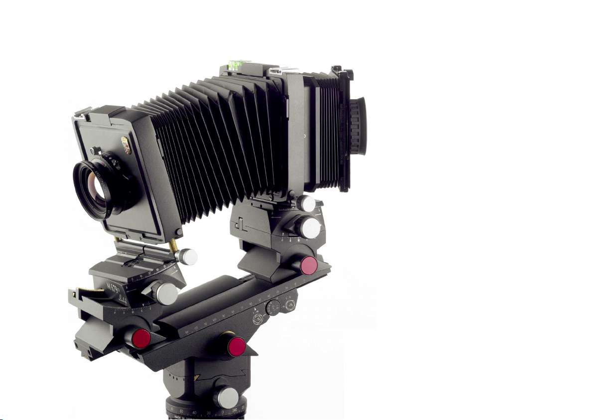
LINHOF M 679
E
cs
Page 2
Con ten ts
1. THE DESIGN PRINCIPLE 5
1.1. THE SYSTEM OF THE M 679cs - ACCESSORIES 6
1.2. ORDERING INFORMATION 7
1.3. TECHNICAL DATA LINHOF M 679cs 8
2. CAMERA DESIGN DETAILS AND ACCESSORIES 9
2.1. FEATURES AND CONTROLS 10
2.2. THE OPTICAL BENCH 12
2.3. THE INTEGRATED LEVELLING BENCHHOLDER 13
2.4. BELLOWS AND BELLOWS CHANGE 14
2.5. THE LENS STANDARD 15
2.6. LENS CHANGE 15
2.7. COMPENDIUMS 15
2.8. REAR STANDARD 17
2.9. M 679cs GROUNDGLASS BACK 17
2.10. GROUNDGLASSES 17
2.11. FOCUSING AIDS 18
2.12. ADAPTERS FOR ROLLFILM AND DIGITAL IMAGING 20
2.13. ADAPTERS FOR DIGITAL BACKS 22
2.14. RAPID CHANGE ADAPTER SLIDE 23
2.15. UNIVERSAL ADAPTER SYSTEM 24
2.16. M 679 COMPONENTS TO USE WITH 4x5 CAMERAS 26
2.17. STAND ALONE POLAROID BACK 27
2.18. THE SYSTAINER TRANSPORTATION LINHOF M 679cs 28
2.19. TRIPODS AND TRIPOD HEADS 29
3. LENSES AND SHUTTERS 30
3.1. LENS SELECTION 31
3.2. IMAGE CIRCLE 32
3.3. LENSBOARDS 33
3.4. SHUTTERS 34
3.5. DIGITAL LENSES 35
4. CAMERA ADJUSTMENTS 36
4.1. VERTICAL AND LATERAL SHIFT (DIRECT DISPLACEMENT) 37
4.2. INDIRECT PARALLEL DISPLACEMENTS 38
4.3. VERTICAL PARALLEL SHIFTS (INDIRECT) 39
4.4. HORIZONTAL PARALLEL SHIFTS (INDIRECT) 41
4.5. COMBINED PARALLEL SHIFTS 42
4.6. SCHEIMPFLUG ADJUSTMENTS 43
4.7. DEPTH-OF-FIELD WEDGE 46
4.8. SUMMARY 47
4.9. DEPTH-OF-FIELD AND DEPTH-OF-FIELD OPTIMIZER 48
4.10. WHAT ABOUT YAWING? 50
4.11. VIEW CAMERA MOVEMENTS MADE SIMPLE 51
3
Page 3
4
Page 4

1. THE DE SIGN P RINC IPL E
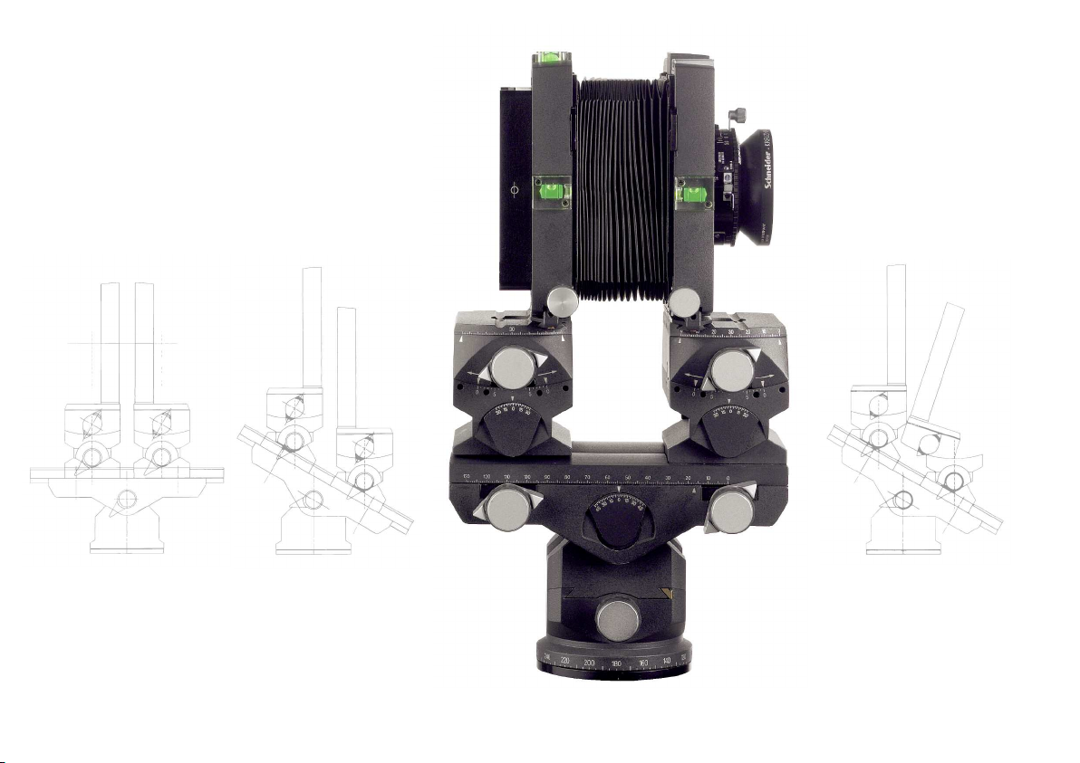
The Linhof M 679cs is a modular view camera for the formats 6x6 cm
/2 1/4 x 2 1/4 in. up to 6x9 cm/2 1ŕ4 x 3 1ŕ4 in.
A special adapter system permits the use with commonly used medium
format systems by utilizing existing magazines. The same adapters for the
various medium format camera systems permit the use of all existing scan
and chip backs. Therefore, the Linhof M 679cs is the ideal tool for all
photographers who:
a. start working with an adjustable camera system by
utilizing their own medium format equipment,
b. need a compact camera system for digital imaging as well as
analogue professional photography on classic rollfilm.
Ease of use, almost unlimited flexibility, and a complete range of accessories make the M 679 the ideal camera.
The following features mean the 679 is capable of being set up, adjusted,
and used with the greatest of ease. The base of the camera is an optical
bench with two parallel rails from 53 (35) -326 mm. This means lenses
from 24 - 240 mm can be used without extension rails.
The M 679cs has been ergonomically designed with precision micro
drives and positive locks for exact, fast and errorfree use.
All movements are made by rotating control knobs. This procedure
guarantees effortless and precise adjustments to be made and easily seen
on the viewing screen.
The method of indirect displacement is used on the M 679cs which
speeds up the work of any photographer. The required result either on
film or on chip is faster and more precisely achieved than with the
conventional method of direct displacement. Micro drives serve for fine
adjustments of lateral and horizontal shifts at the lens standard and the
rear standard.
The integrated panorama benchholder with stepless lateral levelling of
10° not only serves as an additional tilt or ballhead but also allows
precise repetition of a shot because of its calibrated scale.
Front and rear standards are steplessly moved in tilt segments. Thereby
giving permanent yawfree operation, and avoiding converging lines by
exact alignment of the vertical plane, for example, in architectural photography. The basic principles of large format photography are easily
applied on the M 679cs due to the accuracy of all measurement scales.
The front and rear standard can be turned by +/- 30° around the vertical
axis and by 36° and 24° respectively around the horizontal axis.
This feature enables the image circle of the lens to be fully exploited.
This is an optimum in utilization of the image angle and the image circle
of the lenses. The lenses mounted on lensboards are freely accessible
from 3 sides and can be used in all known mechanical and electronic
shutters.
The groundglass back has interchangeable groundglasses for different
formats. A sliding Fresnel screen and a viewer allow the uncomplicated
viewing of a bright and undistorted groundglass image even if the camera
is extremely displaced.
A huge range of accessories permit convenient image control and fast
operation by using the Linhof Rapid Change Adapter Slides.
5
Page 5
1. Th e Des ig n P ri nci ple
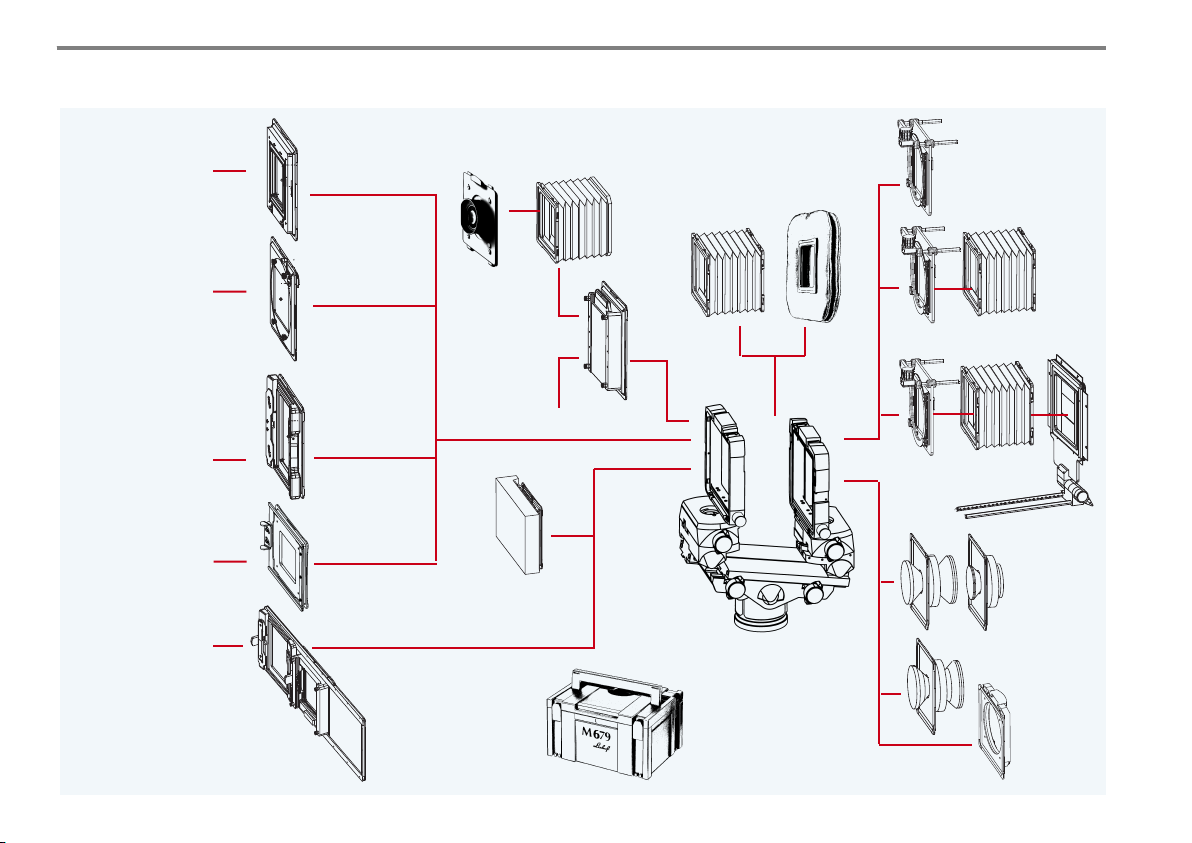
1.1. THE SYSTEM OF THE M 679cs - ACCESSORIES
- Hasselblad backs
- Polaroid back 100
- Accepts all digital
backs for Hasselblad V
- Mamiya RZ
- Polaroid back RZ
- Accepts all digital
backs for Mamiya RZ
- Mamiya RB
back
- Mamiya 6x8
motor back
- Linhof Rapid Rollex
slide-in back 6x7
- Horseman 6x9 cassette
- Silvestri accessories
- Accepts all digital
backs for Mamiya RB
Digital Back Adapter
plates:
- for Hasselblad V, H1
- for Mamiya 645 AF/AFD
- for Contax 645
Universal Rapid
Change Adapter Slide for
Digital Back Adapter plates:
- for Hasselblad V, H1, H2
- for Mamiya 645 AF/AFD
- for Contax 645
Magnifier viewing
Adapter for
Hasselblad
backs
Adapter for
Mamiya RZ
backs
Multi Adapter
Universal Adapter
Rapid change adapter slide M 679
system for Basic
lighthood
Back with
interchangeable
groundglasses
Fresnel screen M 679
M 679
Polaroid Back
M 679 Systainer I
Systainer II
for accessories
Basic
lighthood
Normal
bellows
Wide angle
bellows
M 679
with integrated
levelling benchholder
cs
Filter holder
Basic compendium
M 679 Pro
compendium
Lensboards
for lenses
f 24 - 250 mm
Lensboard
adapter
M 679 for
Technika
lensboards
6
Page 6
1.2. ORDERING INFORMATION
LINHOF M 679cs incl. bellows, front and rear standard,
with integrated benchholder with stepless lateral
levelling, without lens and back 000117
M 679cs Groundglass back 001698-S
Groundglass scoring 3x3 021833-S
Groundglass scoring 6x6 021834-S
Groundglass scoring 6x7 021835-S
Groundglass scoring 6x8 021836-S
Groundglass scoring 6x9 021842-S
Groundglass scoring 24x36 / 36x63 021837-S
Groundglass scoring 37x37 / 37x71 021838-S
Groundglass scoring 37x49 / 49x71 021840-S
Groundglass scoring 33x44 021841-S
Groundglass scoring 72x88 (Anagramm) 021839
Fresnel Screen M 679 002523
Acute Groundglass for M679cs, 37x37 / 37x49 021843-S
Acute Groundglass for M679cs, 33x44 021844-S
Format dial 6x7 M 679cs for format 6x6 - 6x8
(included in camera price M 679cs) 003905
Format dial 3x3 M 679cs 003906
Format dial 6x9 M 679cs 003907
Basic Lighthood M 679 002763-S
Magnifier Viewing System 8x8 for Basic Lighthood 002757
M 679 Adapter for Hasselblad V backs 001694
M 679 Adapter for Mamiya RZ backs 001696
Adapter for Anagramm Scanning back 064924
Multi Adapter for Mamiya RB, Mamiya 6x8 motor cassette,
Linhof Rapid Rollex 6x7, Horseman 6x7/6x8/6x9 001695
Universal Adapter for camera adapter plates 001697
Groundglass Silvestri 6x9 S-24011
Focusing Bellows with Magnifier / Silvestri 6x9 S-25010
Right Angle Attachment / Silvestri 6x9 S-25030
Polaroid Back M 679 001692
Universal Rapid Change Adapter Slide
M 679 24x36 / 36x63 002765-S
1. Th e Des ig n P ri nci ple
Universal Rapid Change Adapter Slide M 679 37x37 / 37x71 and 37x49 / 49x71 002766-S
Adapter plate for Hasselblad V 001700
Adapter plate for Hasselblad H 1, H2 001701
Adapter plate for Mamiya 645 AF / AFD 001702
Adapter plate for Contax 645 001703
Flexible shafts for M 679cs shift (2 pcs.) 002769
Wide Angle Bellows M 679 002754
Normal Bellows M 679 (spare) 002753
Basic Compendium Lensshade M 679 incl. Filter Holder 001939
Pro Compendium M 679 incl. Filter Holder and
Vignetting Mask Holder 001940
Filter Holder M 679 M105x1 and 10x10 cm 001941
Vignetting Mask Holder M 679 001942
Flat Lensboard M 679 size 0 001160
Flat Lensboard M 679 size 1 001161
Flat Lensboard M 679 size 3 001173
Recessed Lensboard M 679, size 0 001163
Recessed Lensboard M 679, size 1 / Rollei Shutter. 001164
Double Recessed Lensboard M 679 size 0 001176
Double Rec. Lensboard M 679, size 1 / Rollei Shutter 001174
3x Recessed Lensboard M 679, size 0 001175
3x Recessed Lensboard M 679, size 1 / Rollei Shutter 001177
4x Recessed Lensboard M 679, size 0 for
Apo-Digitar XL 5,6/35, Copal 0 001178
Lensboard Adapter M 679 / Technika 45 lensboard 001100
Adapter Linhof Kardan for M 679 001101
Adapter Sinar / Horseman for M 679 001102
Adapter Cambo for M 679 001103
Adapter plate for Hasselblad Finder 001104
Adapter plate for Arca Swiss Bino Tube on M 679 001105-S
Systainer M 679 022491
Systainer II M 679 for Accessories 022492
7
Page 7
1. Th e Des ig n P ri nci ple
1.3. TECHNICAL DATA LINHOF M 679cs
Overall camera dimensions in basic position Length: 170 mm, width: 153 mm, height: 294 mm
with integrated panorama benchholder 6.7 x 6.0 x 11.6“
Weight Approximately 4.500 g with integrated benchholder
Maximum camera extension of non-adjusted camera in 326 mm / 12.8“
normal position (lens to film plane)
Minimum camera extension with wide-angle bellows 53 mm with recessed lensboard
(lens to film plane) 40 mm with double recessed lensboard
35 mm with 4x recessed lensboard
Indirect parallel adjustment (up/down), maximum extension 168 mm / 6.6“
and tilting angle of the optical bench of 30°
Indirect vertical parallel shift (up/down) minimum extension 38 mm / 1.5“
and tilting angle of optical bench 30° (limitations with focal lengths of less than 47 mm)
Indirect horizontal parallel shift (lateral shift left/right) 168 mm / 6.6“ maximum extension
Indirect horizontal parallel shift (lateral shift left/right) 38 mm / 1.5“
minimum extension (limitations with focal lengths of less than 47 mm)
Direct cropping correction lens standard Lateral shift right - left 20 mm, Vertical shift 20 mm
Direct cropping correction rear standard Lateral shift right - left 20 mm, Vertical shift 20 mm
Panorama benchholder Tilting front 45°, rear tilting 45°
Panorama rotation 360°,
lateral levelling 10° each side
Tilts of front and rear standard to optical bench 30° each front and rear
Front standard / Rear standard Vertical axis swing +/- 30°
Tilting around the horizontal axis front 18° / 12°
Tilting around the horizontal axis rear 12° / 18°
8
Page 8
2. C A MER A DESI GN DET AIL S A ND AC C ESS ORIE S
The Linhof M 679cs is a system camera
with an utmost flexibility of the individual
system components.
The basic idea is an optimum operation
ease. Therefore the system is continuously
updated to the current needs.
The basic lighthood serves
as a light shield permitting
viewing in brighter areas.
The magnifier viewing adapter 8x8 can be linked to the
basic lighthood.
9
Page 9
35
34
33
32
31
30
29
28
27
26
25
24
23
22
21
20
19
18
17
16
1010
2. Cam era D es i gn D eta ils a nd A c ce sso rie s
1
2
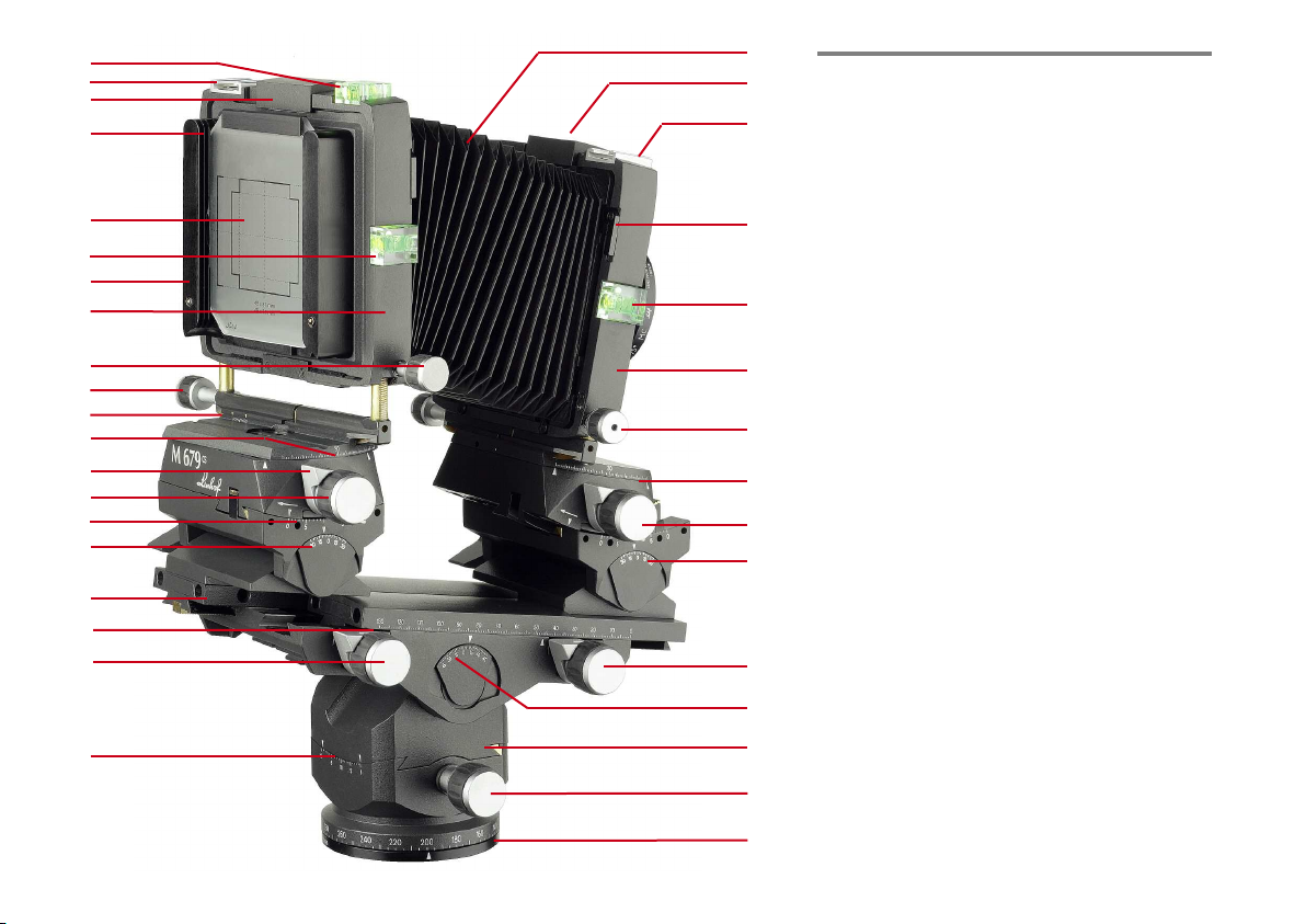
2.1. FEATURES AND CONTROLS
3
1 Normal bellows
2 Unlocking of lensboard
3 Accessory shoe for filter holder,
compendium etc.
4 Lever for change of bellows
4
5 Spirit level to control adjustment of lens
standard to vertical
6 Lens standard
5
7 Self-aligning micro drives for horizontal
shift of the lens standard
8 Scale for swinging the lens standard around
6
the vertical axis
9 Rack and pinion drive for tilting of the lens
7
standard around the horizontal axis
10 Scale for basic tilting angle of the lens standards
11 Turning knob for basic extension and for
8
close up focusing
12 Scale for tilting angle of the optical bench
9
13 Integrated panorama benchholder with stepless
10
self-aligning lateral levelling and panorama
rotation
14 Rack and pinion drive for lateral levelling
15 Scale for panorama rotation of the benchholder
16 Scale for lateral levelling
17 Focusing knob
11
18 Scale for focusing and further extension
19 Rails of the optical bench
12
20 Scale for basic tilting angle of the rear standard
21 Scale for tilting angle of the rear standard
13
22 Rack and pinion drive for tilting of the rear
14
standard
23 Integrated locking lever at the turning knobs
24 Scale for swinging of the rear standard
15
25 Scale for lateral shift (cropping correction)
Page 10
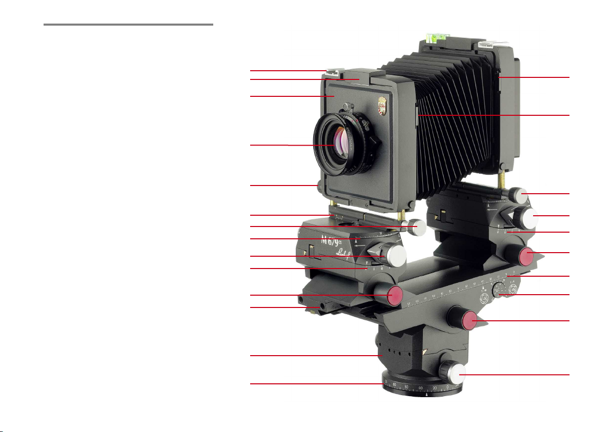
2. Cam era D es i gn D eta ils a nd A c ce sso rie s
26 Rack and pinion drive for lateral shift
of the rear standard
27 Rack and pinion drive for vertical shift
of the rear standard
28 Rear standard
29 Groundglass back for interchangeable
groundglasses and focusing aids
30 Spirit level for adjusting the rear standard to
vertical for avoiding converging lines
31 Interchangeable format groundglasses
32 3 grooves for easy change of groundglasses,
Fresnel screens and basic lighthoods
33 Unlocking device for groundglass back,
adapters and Rapid Change Adapter Slides
34 Accessory shoe
35 Spirit level for horizontal adjustment
36 Rack and pinion drive for swinging the rear
standard around the vertical axis
37 Scale for tilting of the lens standard around
the horizontal axis
38 Basis locking of the rear standard
39 Scale for focusing and increased extension
40 Depth-of-field optimizer
41 Locking lever for panorama benchholder
42 Locking knob of panorama rotation
43 2 holes for compendium guide rails
44 Basis locking of the lens standard
45 Scale for tilting of the lens standard around
the horizontal axis
46 Rack and pinion drive for swinging of the
lens standard around the vertical axis
47 Scale for swinging of the lens standard
48 Rack and pinion drive for lateral shift
49 Scale for lateral shift of the lens standard
50 Interchangeable lens
51 Lensboard M 679
3
2
51
50
7
49
48
47
46
45
44
43
13
15
26
36
37
38
39
40
41
42
11
11
4
4
Page 11
2. Ca mer a De s ig n Det ail s an d A cc ess ori es
2.2. THE OPTICAL BENCH
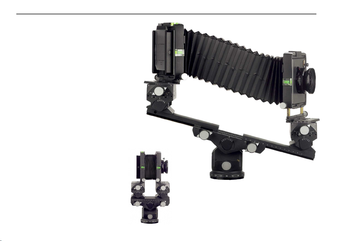
The base of the camera is an optical bench with
two parallel guided rails. Although extremely
compact, the camera offers sufficient extension
up to maximum 326 mm for long focal lengths
– as well as for close ups. This means starting
with wide-angle of 24 mm to tele 240 mm.
The focal length is coupled with the taking
format: 240 mm with 6x7 cm format corresponds to 450 mm with 4x5 in. format.
The telescoping extension of the optical bench
can be reached with the front and rear standard. For better balancing the extension should
always be made with both standards. Focusing
is effected with the same elements also realizing the extension changes: the camera can be
focused with the front standard as well as with
the rear standard. The rear standard has got the
depth-of-field optimizer (40) guaranteeing the
calculation of the exact focus point. Turning
knob (11) und focusing knob (17) have integrated locking levers (23), which should always be
applied after any change of the extension or
change of focus.
Both standards are linked to base tilt elements
serving to adjust the camera to vertical for vertical parallel displacements (38, 44).
Camera shown with
maximum extension.
Camera shown in
compact position.
12
Page 12
2.3. INTEGRATED LEVELLING
BENCHHOLDER
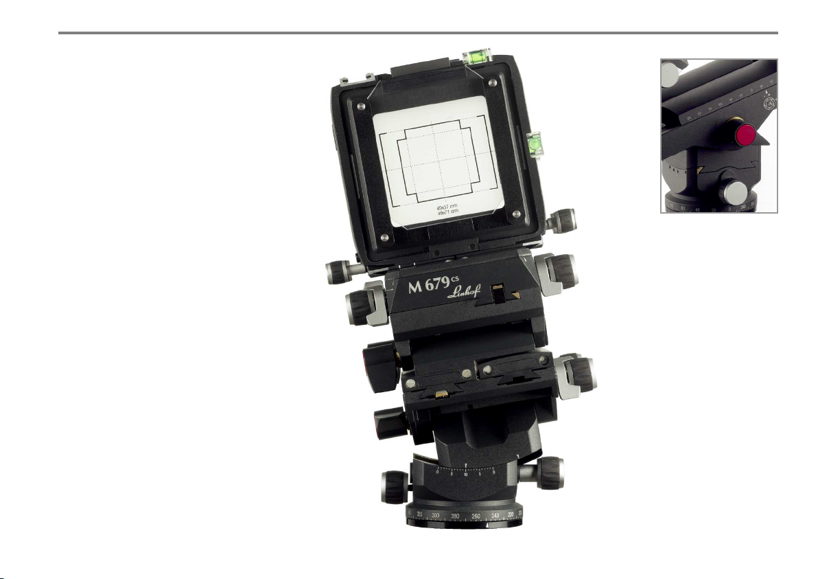
Any studio camera requires a pan/tilt head or
ballhead. The Linhof M 679cs is supplied with
an already integrated panorama benchholder
offering many advantages: various adjustments
or extreme displacement make it necessary to
know the exact angle of the tilting degree.
Therefore, the integrated benchholder of the
M 679cs has a precise angle scale. The maximum tilting to either side is 45°, the panorama
rotation is 360°.
All displacements start with the benchholder:
unlock the holder (41), set the camera to the
subject and lock. The built-in zero click and a
retention spring facilitate the operation.
The integrated panorama bench holder features
a stepless lateral levelling of 10° each side by
means of self-aligning micro drives. Practically
all photographic problems can now be solved
without the need of an additional tripod head.
2. Ca mer a De s ig n Det ail s an d A cc ess ori es
Attention please:
Locking after each
displacements with the
red coloured levers is
strongly advised (38,
41, 44).
The integrated panorama
benchholder with 3/8“
retaining socket.
13
Page 13
2. Ca mer a De s ig n Det ail s an d A cc ess ori es
2.4. BELLOWS AND BELLOWS CHANGE
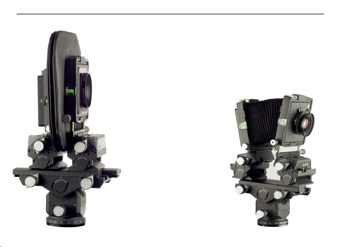
Lenses of different focal lengths require different camera extensions. The normal bellows
can be exchanged very quickly with the wideangle bellows (and vice versa): unlock each
lever right and left at the inner lens and rear
standard (4).
The normal bellows is very flexible but at the
same time stable enough to allow extreme displacements.
The wide angle bellows (Code 002754) of the
Linhof M 679cs is double-folded permitting
extreme extensions. Therefore, the extension
range is wide enough to avoid changing the
bellows unnecessarily.
The wide angle bellows is used for focal length
of 24 – 90 mm, the normal bellows is used for
lenses with focal lengths of 90 to 240 mm.
14
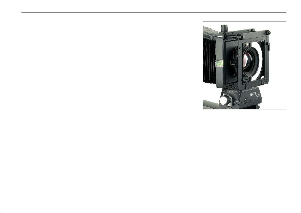
M 679cs with
wide angle bellows,
35 mm lens and
lens rise.
Linhof M 679cs with
normal bellows
Page 14
2. Ca mer a De s ig n Det ail s an d A cc ess ori es
2.5. THE LENS STANDARD
By swinging around the vertical and horizontal
axis lenses over 90 mm focal length are turned
around the principle point in such a way that
the framing chosen before is hardly changed.
The lenses mounted on lensboards are freely
accessible from 3 sides utilizing all known
mechanical and electronic shutters.
Linhof supplies lenses complete with shutter
mounted on the appropriate lensboard.
Informations for lens selection, lensboards and
shutters please see chapter 3.
2.6. LENS CHANGE
Lenses/lensboards are easily changed by a
click clack mechanism: just unlock a lever (2)
and the lensboard is free. Insert the lensboard
by simply pressing into the snap-on device.
(We recommend a hand counter pressure at
the standard.)
The lensboard is square, the lens is exactly
centered in the board which can therefore be
inserted in either way right and left.
Cables of digital shutters can therefore be
used from any side.
2.7. COMPENDIUMS
For obtaining brilliant pictures a compendium
is a must for adjustable cameras. Lenses with
the huge image angle of view of applied photography require an appropriate lensshade.
Such a lensshade should also offer sufficient
adjustment facilities.
A compendium is an indespensible accessory
as it ensures best possible exposures of flarefree definition, contrast and colour saturation.
For the M 679cs two compendiums with integrated filterholder are offered.
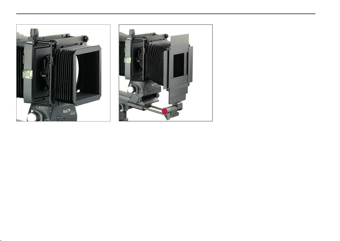
The FILTER HOLDER M 679 (001941) can also
be ordered separately. This accessory is adapted to the accessory shoe accepting gelatine
filter and up to 2 acryl glass filter 10x10 cm as
well as screw-in filter M 105 x 1.
For changing lenses the basic compendium can
remain at the camera: With the counter part of
the accessory shoe the compendium can be
moved aside.
Filter holder on the M 679
15
Page 15
2. Ca mer a De s ig n Det ail s an d A cc ess ori es
The filterholder of the Pro Compendium is inserted in the accessory shoe of the camera body.
For special effects, double exposures, section
framings and as a protection against unwanted
side light there are vignetting blinds available.
The M 679 Professional Compendium with
intelligent adaptation at the optical bench
The BASIC COMPENDIUM (001939, incl. filter
holder) consists of a small flexible self-supporting bellows and is supplied complete with filterholder. The basic compendium has to be
adapted to the filterholder. The self-supporting
bellows can olso be utilized as basic lighthood.
With the counter part of the accessory shoe the
compendium can be moved aside after unlocking the knob.
16
The M 679 PROFESSIONAL COMPENDIUM
(001940) consists of the filterholder, a M 679
normal bellows and the vignetting mask holder
and will be supplied as a complete unit.
This compendium is centered automatically.
It is inserted into the optical bench and is therefore always in the optical axis. It is sufficient to
align the compendium standard parallel to the
rear standard using the red locking lever.
Page 16
2.8. REAR STANDARD
The maximum usable format is 6x9 cm.
Special adapters for each system are the link for
compatibility with the commonly used medium
format systems by utilizing existing magazines
(analogue and digital). Swinging is principally
made around the vertical and horizontal axis in
the format centre which means that the image
center once focused sharp will remain sharp at
any displacement.
All backs are freely accessible from the three
sides. The easily detachable groundglass back
accepts the groundglasses as well as various
viewing aids.
2.9. GROUNDGLASS BACK
The detachable groundglass back accepts
various groundglasses and viewing aids.
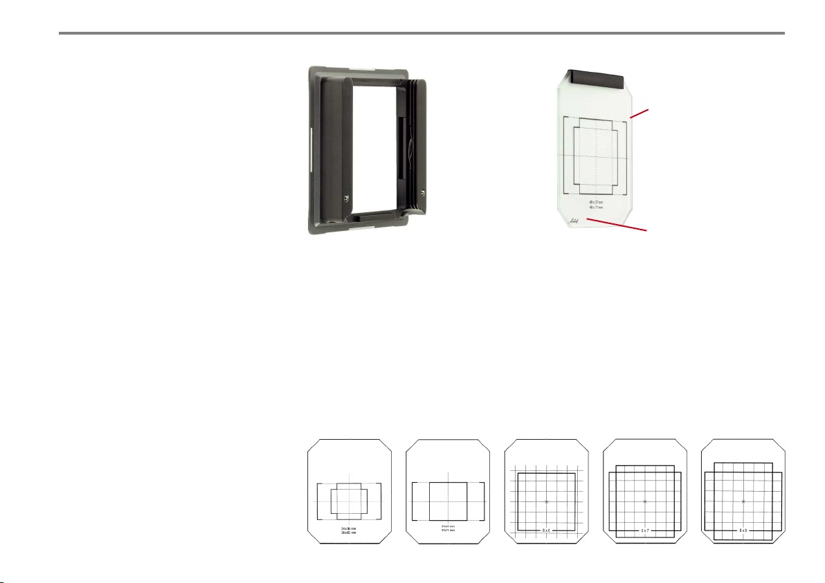
The M 679cs
groundglass back
(001698-S) has
3 grooves for inserting the interchangeable format
groundglasses, the
Fresnel screen as
well as the viewing
aids.
2.10. GROUNDGLASSES
Several groundglasses according to the required
formats are offered with grids of 3x3 cm up to
6x9 cm. The groundglass is changed with the
aid of a small handgrip, therefore no screws, no
2. Ca mer a De s ig n Det ail s an d A cc ess ori es
Interchangeable format
groundglasses with
scoring for stitching facilities in combination with
rapid change adapter
slide.
The groundglasses "S" matching the groundglass back
001698-S have the imprinted
logo in the bottom left corner
for better identification.
clamps. The groundglass is inserted into the first
groove at the camera back. The only exception
is the the Silvestri 6x9 groundglass used as an
attachment to the multi adapter.
VERTICAL OR HORIZONTAL FORMAT
By simple fingertip pressure the groundglass
back with inserted groundglass can be unlocked and be taken off for change of vertical
to horizontal format, sometimes even with
attached viewing aid.
The corresponding interchangeable format groundglasses can be changed by using the handgrip.
17
Page 17
2. Ca mer a De s ig n Det ail s an d A cc ess ori es
„ACUTE“ GROUNDGLASS (021843-S)
The „Acute“ groundglass is known to be super
bright allowing easier composition and focusing even with extremely short focal lengths.
To use the original „Acute“ groundglass with
the Linhof M 679 system we have framed this
glass inside a metal plate matching the same
outer dimensions as the original Linhof groundglass. An easy and quick exchange from the
„Acute“ to the Linhof groundglass is possible
at any time.
There are two formats available for the Acute
groundglass M 679cs: Code No. 021843-S
for format 37x37 / 37x49 mm and Code No.
021844-S for format 33x44 mm.
2.11. FOCUSING AIDS
By viewing via groundglass the image control
is facilitated by various system accessories.
THE M 679 FRESNEL SCREEN
For increasing the brightness of the image
corners when using short focal lenghts socalled Fresnel screens are used.
With the Linhof M 679 the optical centre of the
Fresnel screen is offset from the centre of the
screen. In addition it can be moved up and
down which means that the brightest part can
be positioned on the darker portions of the
focusing screen. Because of this a right angle
viewfinder can be used without image vignetting. By turning the complete groundglass back
by 90° also the darker parts of the lateral shift
can be compensated.
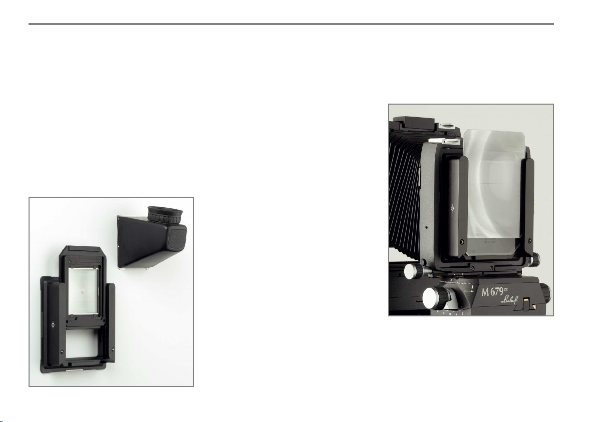
The Fresnel screen is placed over the ground-
The Acute groundglass is slotted into the first groove
of the groundglass back M 679. The rear side of the
metal plate accepts all Hasselblad finder systems.
glass with the grooved side towards the lens.
It is slotted into the 2nd groove of the groundglass back permitting easy moving up and
down.
The Fresnel screen can be moved up and
down. The illustration shows the use of the
Fresnel screen at lens rise. By fully utilizing
the special design of the screen we have not
only moved it up but also inserted the screen
with the offset center in top position.
18
Page 18
2. Ca mer a De s ig n Det ail s an d A cc ess ori es
FURTHER VIEWING AIDS
The following accessories are furthermore
available:
Adapter plate for Arca Swiss Bino Tube
(001105-S): This item is slotted into the 3rd
groove of the groundglass back accepting the
Acra Swiss Bino Tube, enabling a binocular
upright image control.
Adapter plate for Hasselblad Finder (001104):
This adapter permits the use of the Hasselblad
Hasselblad reflex finder RMFX allowing to
control an 6x6 image section (see illustration
opposite page).
This Hasselbald finder is especially recommended in combination with the Acute groundglass
M 679cs.
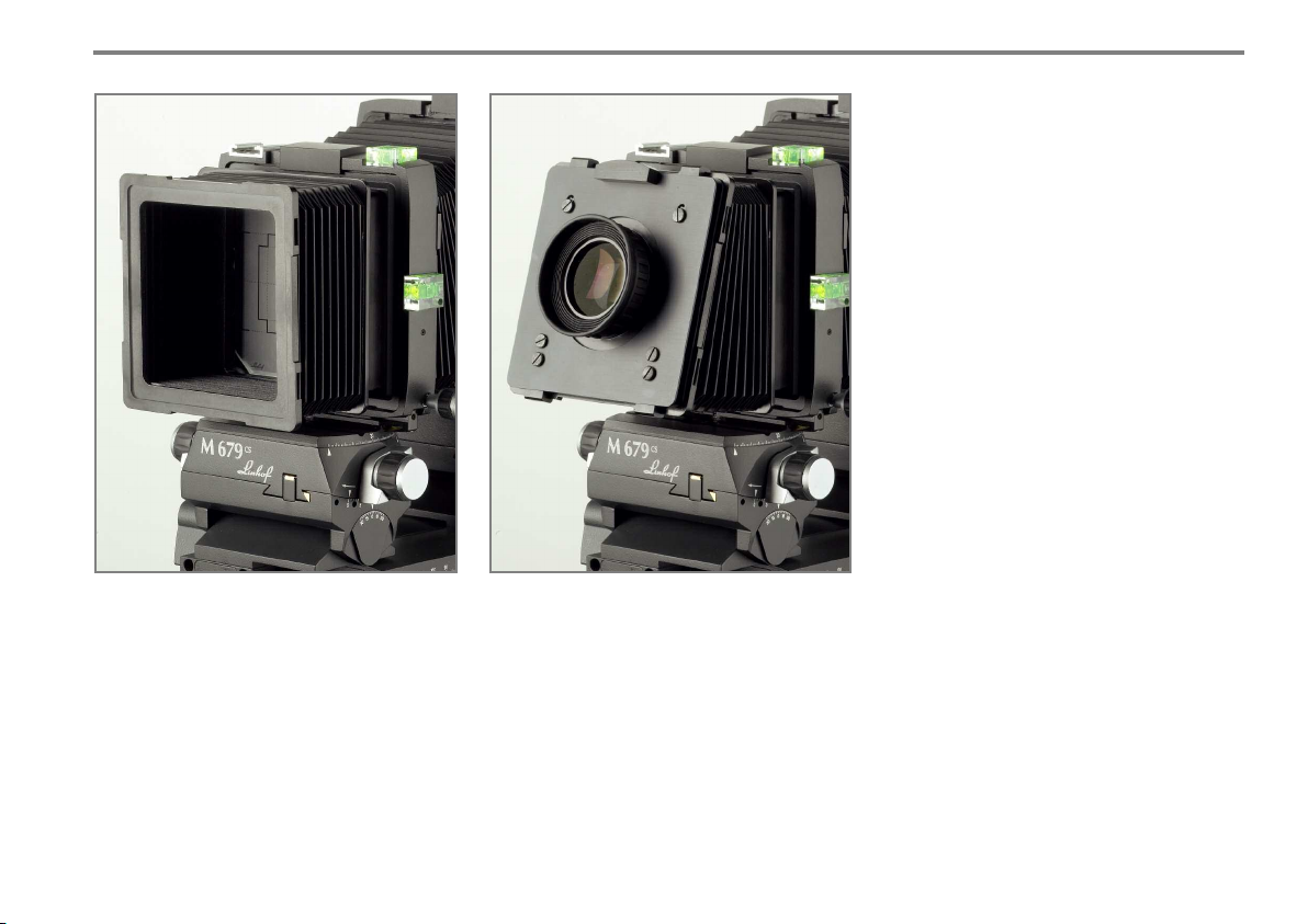
THE BASIC LIGHTHOOD (002763-S) serves
as light shield permitting viewing in brighter
areas. The basic lighthood consists of a selfsupporting flexible bellows identical with the
bellows of the basic compendium. The basic
lighthood is slotted behind groundglass and
Fresnel screen in to the third groove of the
groundglass back.
THE MAGNIFIER VIEWING ADAPTER 8x8
(002757) to be attached to the basic lighthood
permitting viewing of the total groundglass area.
19
Page 19
2. Ca mer a De s ig n Det ail s an d A cc ess ori es
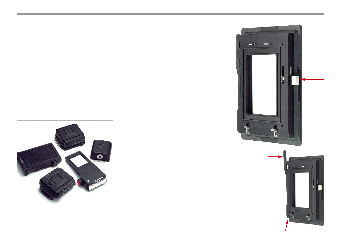
2.12. ADAPTERS FOR ROLLFILM
AND DIGITAL IMAGING
The Linhof M 679cs is a universal tool by using
various medium format magazines for classical
rollfilm photography as well as for digital backs
for electronic imaging. Special adapters for
each system are the link.
Medium format rollfilm backs which can be
adapted at the M 679cs.
20
THE HASSELBLAD V ADAPTER
Acccepts the complete Hasselblad V back
technique such as rollfilm magazines, Polaroid
magazine 100, and all backs adaptable to
Hasselblad V.
Operation when using rollfilm magazines:
Place rollfilm in the supply chamber and
advance the film with the crank of the magazine to the first frame. After exposure of the first
frame it is necessary to actuate the slide at the
adapter four times in order to release the
locking of the transport crank (1). Advance film
now with the crank until the counter shows
frame number 2. Stop advancing when the
white index mark is visible in the small window. For every further exposure advance the
film normally with the crank. For correct frame
distances please observe that you can definitely
see the white index mark with every exposure.
When using the Hasselblad Polaroid back it is
necessary to move the metal lever situated at
the left lower side of the Hasselblad adapter
upwards (2). This lever (3) serves for detaching
the Polaroid back from the adapter by pressing
it in the right hand direction. Once used, the
lever can be returned to its original position.
1
3 For detaching the
Polaroid back from
the adapter press in
the right hand
direction.
2 When using the
Hasselblad Polaroid
back it is necessary to
move the metal lever
upwards (2).
2
Page 20
2. Ca mer a De s ig n Det ail s an d A cc ess ori es
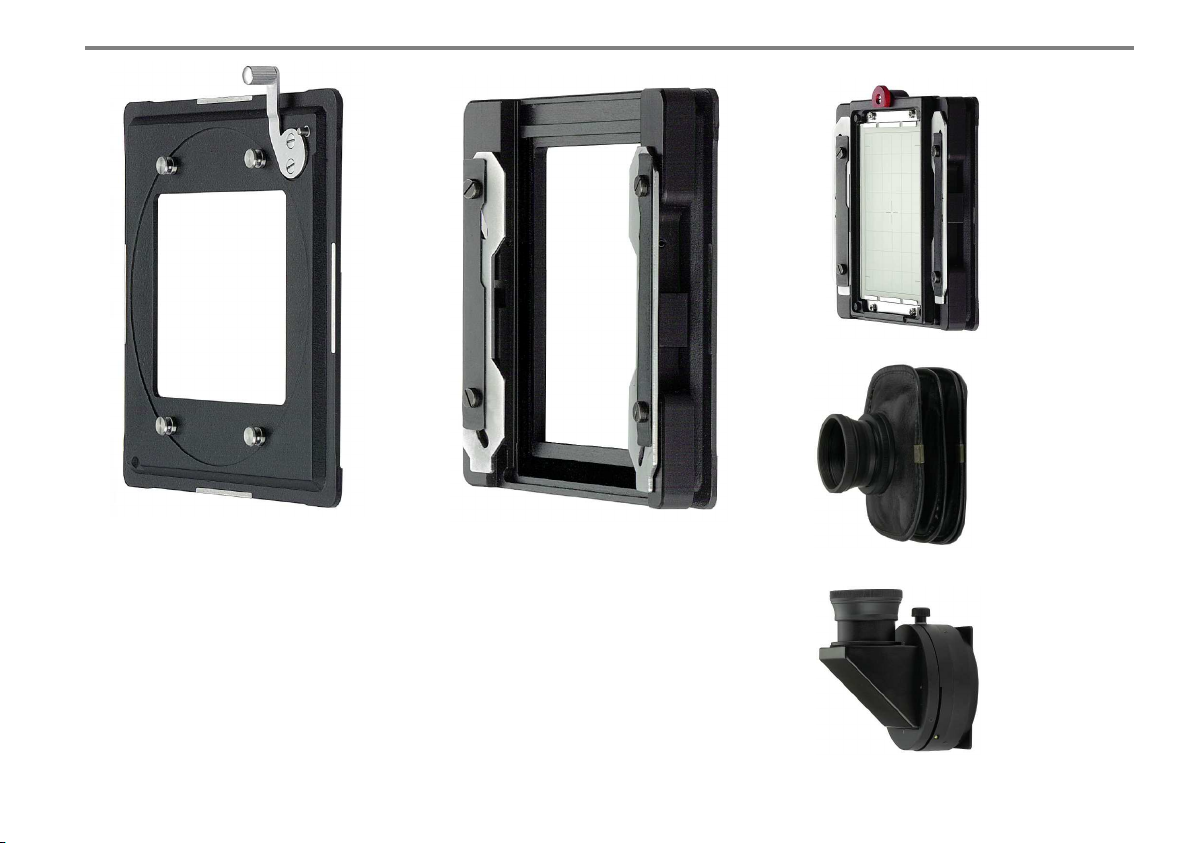
Multi adapter with
Silvestri special
groundglass 6x9
Fits on the
Multi adapter:
Silvestri focusing
hood with
magnifier.
THE MAMIYA ADAPTER
To be used for RZ magazine Pro 2, Polaroid
cassette RZ and all digital backs adapted for
the Mamiya RZ.
Operation when using rollfilm cassettes:
Transport film to the first frame with the
winding knob on the magazine. After each
exposure press lever to the right (lever situated
top right at the adapter) to release for winding
the next frame.
THE MULTI ADAPTER
Accepts the Mamiya RB magazine Pro SD, the
Mamiya 6x8 motor cassette, Horseman back
6x7/6x8/6x9, the Linhof Rapid Rollex slide-in
cassette 6x7 as well as Silvestri system accessories. Cassettes, accessories and backs are held
by a slide locking mechanism.
The Multi Adapter accepts all digital backs
adapted to Mamiya RB.
Fits on the
Multi adapter:
Silvestri right angle
attachment.
21
Page 21
2. Ca mer a De s ig n Det ail s an d A cc ess ori es
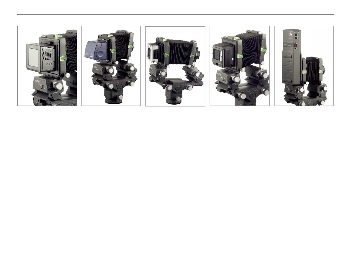
2.13. ADAPTERS FOR DIGITAL BACKS
The Linhof M 679cs offers the freedom to use either the digital back of
your choice or rollfilm backs without complicated modifications.
An intelligent adapter system permits the operation of all commonly used
digital backs and medium format rollfilm backs for 6x6 to 6x9 cm.
Tailor-made accessories are available for any creative idea including the
precisely milled quality adapters.
You can choose adapters for digital backs or rollfilm backs. For example:
Hasselblad Adapter V ( 001694), Mamiya RZ Adapter (001696) or MultiAdapter for Mamiya RB, Linhof Rapid Rollex, Horseman, Silvestri acces-
sories (001695). Or you choose the Universal Adapter (001697) in combination with the corresponding camera adapter plate for your digital back.
The perfect workflow with groundglass viewing permits the Rapid Change
Adapter Slide (02765-S or 02766-S) for quick change of image composition to picture taking. You have the option to enlarge the image area
by stitching.
22
The Linhof M 679cs – the ideal
platform for digital professional photography.
Page 22
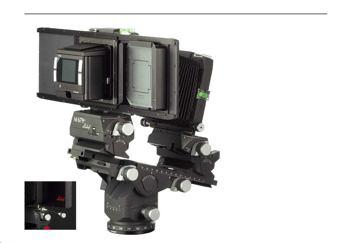
Flexible shafts
(code 002769)
permit smooth vertical or horizontal
shifting with adapted Rapid Change
Adapter Slide.
2. Ca mer a De s ig n Det ail s an d A cc ess ori es
2.14. RAPID CHANGE ADAPTER SLIDE
The Linhof Rapid Change Adapter Slide permits
continuous work flow by rapidly changing the
complete image composition to picture taking
without taking off or attaching backs.
At the same time the chip of the digital back is
protected against dust and mechanical damage.
The Universal Rapid Change Adapter Slide is
attached to the rear standard the same way as
the groundglass back. The slide permits stitching: 2 or 3 shots enlarge the image size of the
digital back. Camera adapter plates suiting the
different cameras in the market firmly connect
the digital back with the slide.
Presently 2 different Universal slides are offered: One for chip formats 24x36 mm and one
for 37x37 mm plus 37x39 mm. The corresponding groundglasses show the formats of the
chip sizes with stitching.
As the Rapid Change Adapter Slides (002765-S
and 002766-S) are supplied with integrated
groundglass back (001698-S) all viewing aids
can be attached.
Rapid Change Adapter Slide
with digital back
FLEXIBLE SHAFTS (002769) permit smooth
vertical or horizontal shifting with adapted
Rapid Change Adapter Slide.
23
Page 23
2. Ca mer a De s ig n Det ail s an d A cc ess ori es
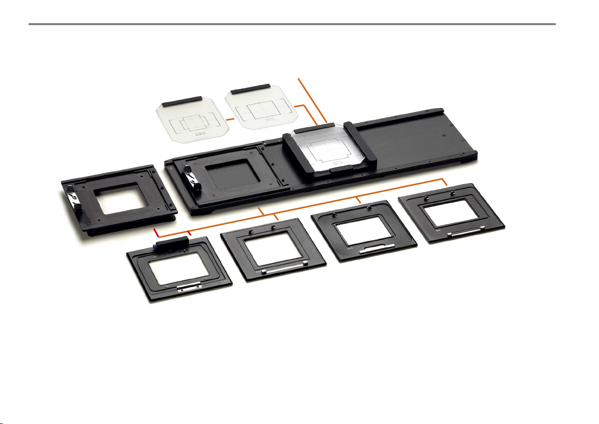
2.15. UNIVERSAL ADAPTER SYSTEM
Groundglass 24x36 / 36x63
(021837-S)
Universal Adapter for Camera
Adapter plates (001697)
Adapter plate for H1, H2 (001701)
Groundglass 37x37 / 37x71
(021838-S)
Groundglass 37x49 /
49x71 (021840-S)
Adapter plate for Hasselblad V
(001700)
Acute Groundglass 37x37 / 37x49 (021843-S)
Acute Groundglass 33x44 (021844-S)
Adapter plate for
Mamiya 645 AF/AFD (001702)
Universal Rapid Change Adapter Slide
M 679 (002765-S u. 002766-S)
Adapter plate for
Contax 645 (001703)
24
Digital backs adapted to different medium format
cameras can be combined with digital backs for
use with the ingenious view camera system Linhof
M 679cs.
Page 24
2. Ca mer a De s ig n Det ail s an d A cc ess ori es
THE LINHOF M 679 UNIVERSAL ADAPTER
SYSTEM offers even more compatability to
digital backs: Digital backs adapted to different
medium format cameras can be combined with
digital backs for use with the ingenious view
camera system Linhof M 679cs.
VIEWING VIA MONITOR
A combination of precision adapters is the link
of the Linhof M 679cs with the digital back.
When controlling via monitor the new
Universal Adapter code 001697 will be required. Now the photographer can work with digital backs of either Hasselblad V, H1, H2,
Mamiya 645 AF/AFD or Contax 645 using if
required in parallel the Linhof M 679 as an
adjustable view camera for applied photography.
VIEWING VIA GROUNDGLASS
For digital photography with professional displacements via groundglass control we recommend the Linhof Rapid Change Adapter Slide
which is now also offered as Universal Adapter
Slide with additional Adapter plates. This slide
permits the quick and easy move from composition to exposure.
The digital back and the Universal Adapter
Slide with corresponding Adapter plate are perfectly linked by a safety locking system with
either Hasselblad H1 and H2, Hasselblad V,
Mamiya 645 AF/AFD or Contax 645.
CHIP SIZE 24x36 mm
We offer 2 alternatives for different chip sizes
relating to the exposure area: For sensor size
24x36 mm you will require our Universal
Adapter Slide code 002765-S with corresponding groundglass code 021837-S. Thanks to
integrated stops (white marks) stitching is made
possible: 3 exposures will enlarge the exposure
area to 36x63 mm.
CHIP SIZE 37x37 mm
For larger chip formats of 37x37 mm and
37x49 mm the Universal Adapter Slide code
002766-S is available.
Chip format 37x37 mm with groundglass code
021840-S can be enlarged by stitching (2 exposures) reaching a total format of 37x71 mm.
CHIP SIZE 37x49 mm
Also here the Universal Adapter Slide code
002766-S is needed in combination with groundglass code 021840-S. Exposure area can be
enlarged by stitching. By two exposures the
area will reach 49x71 mm.
ACUTE GROUNDGLASS
The M 679cs Acute groundglass can also be
used with the Universal Rapid Change Adapter
Slide. Scorings are for formats 37x37/ 37x49
(021843-S) and 33x44 (021844-S).
25
Page 25
2. Ca mer a De s ig n Det ail s an d A cc ess ori es
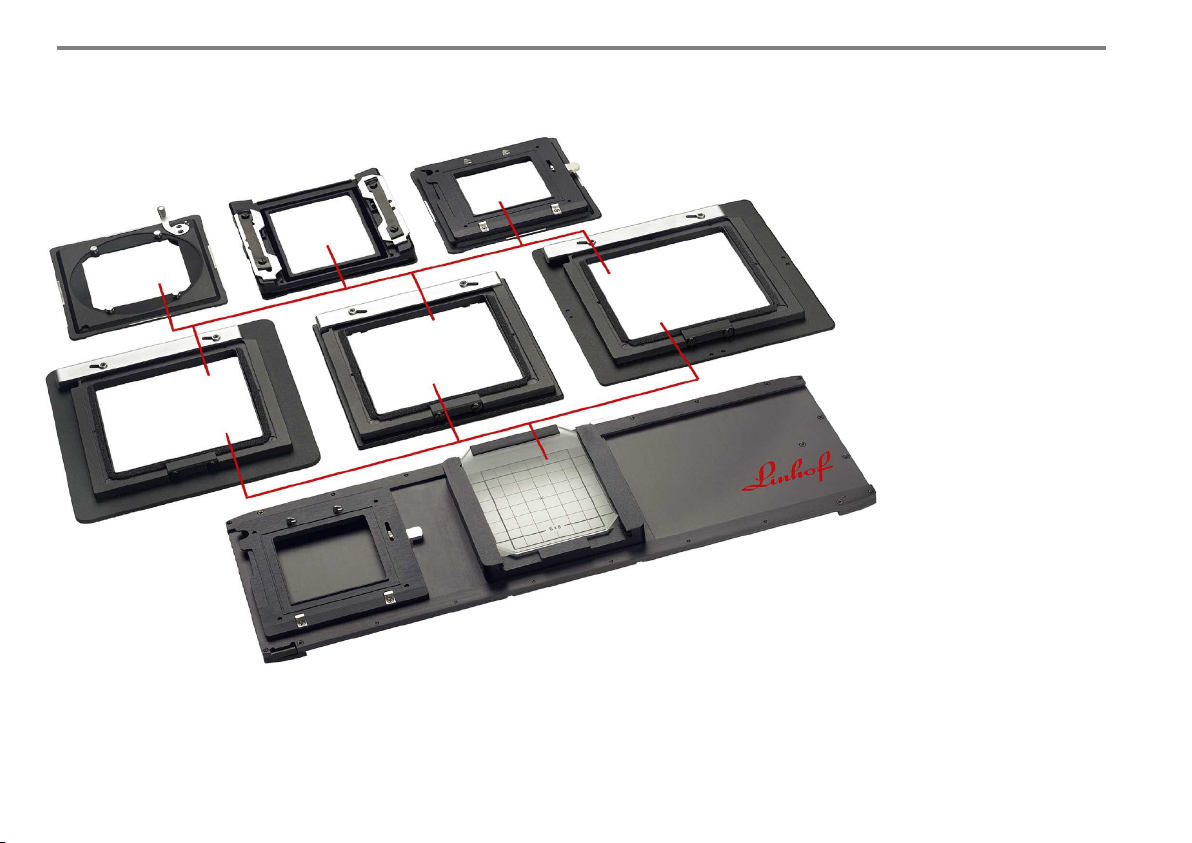
Mamiya RZ
(001696)
Cambo (001103)
Multi-Adapter
(001695)
Hasselblad-V-Adapter
(001694)
Sinar, Horseman
(001102)
Linhof Kardan
(001101)
Universal Rapid Change Adapter Slide
(002765-S, 002766-S)
2.16. M 679 COMPONENTS
TO USE WITH 4x5 CAMERAS
The Universal Adapter
(001697) as well as both
Universal Rapid Change
Adapter Slides (002765-S and
002766-S) can be attached to
9x12 / 4x5 view cameras such
as Linhof Kardan, Sinar,
Horseman and Cambo.
The Linhof Adapters (001101,
001102 and 001103) for different Linhof and non-Linhof
cameras offer compatibility to
the Linhof M 679.
Lenses mounted on M 679
lensboards can be attached to
these adapters.
Adapter for 4x5” cameras for using M 679 components
26
Page 26
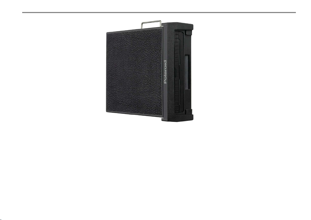
Polaroid back for Linhof M 679
2. Ca mer a De s ig n Det ail s an d A cc ess ori es
2.17. STAND ALONE POLAROID BACK
This Polaroid back especially developed for the
Linhof M 679 utilizes the 600 range of Polaroid
films. This Polaroid back is used independently
from the individual format. Instant photography
over the entire area for quick image composing
and exposure control.
27
Page 27
2. Ca mer a De s ig n Det ail s an d A cc ess ori es
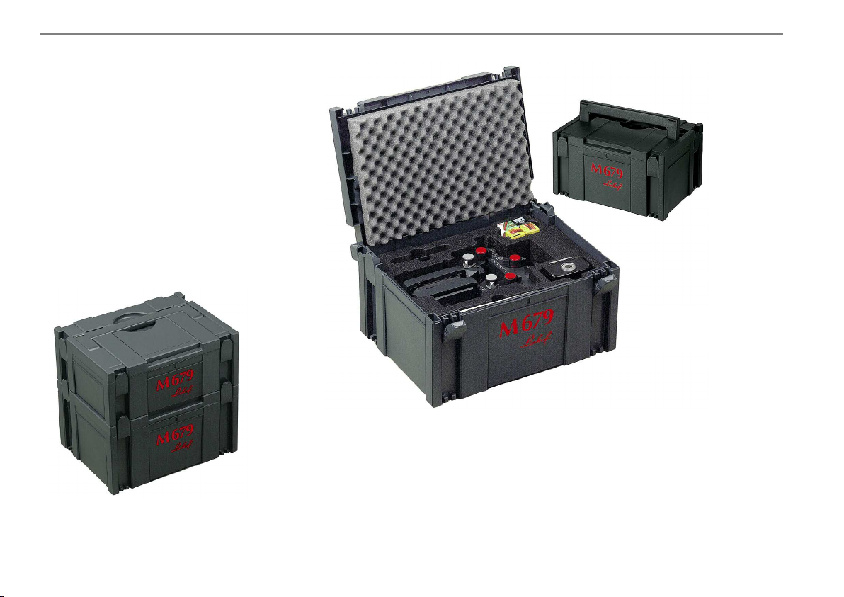
2.18. THE SYSTAINER TRANSPORTATION
LINHOF M 679cs
The Linhof M 679cs is packed and dispatched
in an "intelligent box", called systainer with the
following advantages:
No packing waste and the systainer offers a
shock-resistant transportation facility accepting
the camera with bellows plus back plus one
lens, one adapter, one rollfilm magazine and
the operating manual of the M 679. Furthermore, films can be stored.
The Systainer serves
as transport packing and
camera case.
The patented latch allows quick and safe
linking of several systainers which can then
be transported on a single handle.
28
When packing the camera for transportation
with all adjustments in neutral position the rails
should be set to the index marks on both sides
approximately 5. The normal bellows, one lens
mounted on lensboard as well as the groundglass back can remain at the camera.
All knobs / clamping elements should be firmly
but not excessively locked.
The patented latch allows quick and safe linking of several systainers which can then be
transported on a single handle for any further
amount of accessories.
Page 28
2. Ca mer a De s ig n Det ail s an d A cc ess ori esr
PLEASE NOTE:
When inserting the M 679cs into the
systainer case, please ensure the following:
1. All movements are set to zero.
2. The main track focusing should be set
to 5 mm front and rear.
3. The red lock levers are facing upwards.
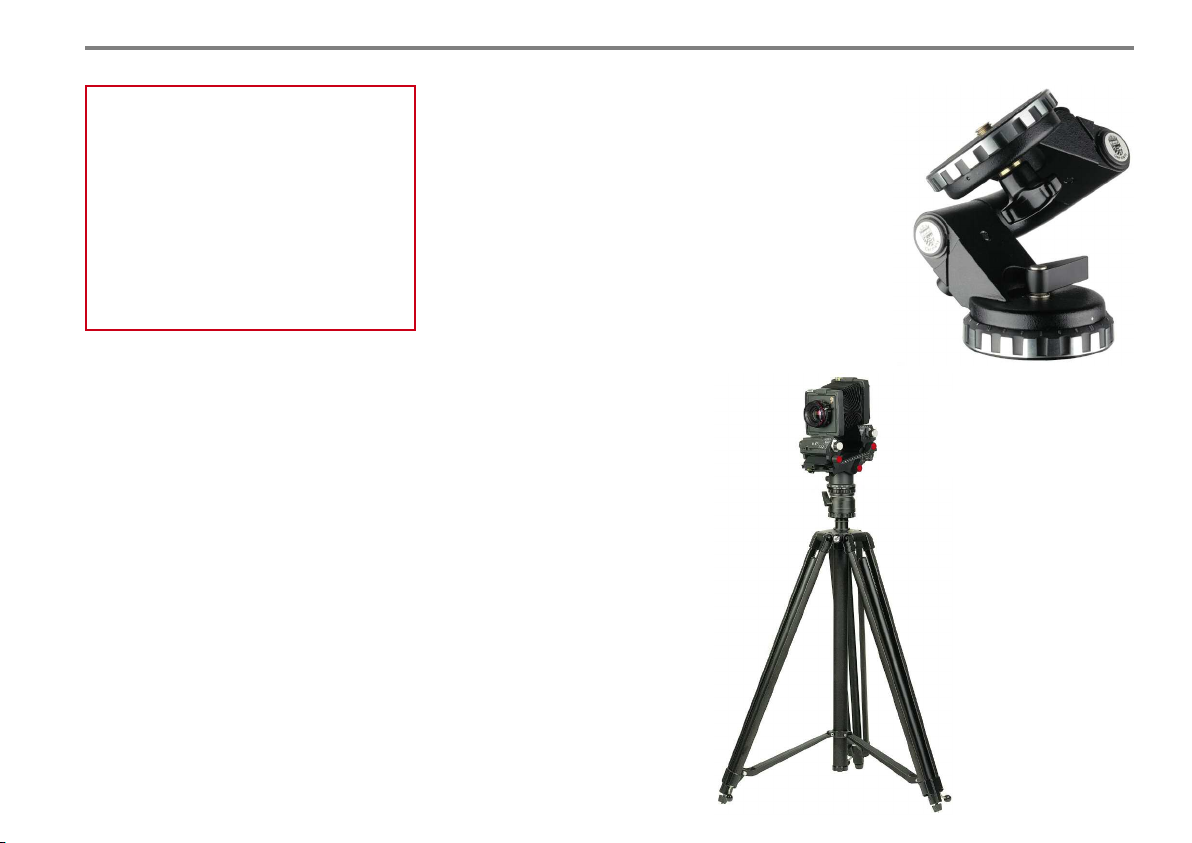
2.19. TRIPODS AND TRIPOD HEADS
Obviously, the selection of a tripod combination that matches the stability and precision of
the camera is of vital importance.
For studio work a medium sized studio stand
(Linhof Studiomatic I, 003467) is recommended
with precision adjustable cross arm and accessory tray for magazines and backs.
For shooting on location we recommend the
Linhof Twin Shank Pro Tripod (003317 or
003333).
For most tasks the M 679cs integrated
levelling panorama benchholder will
be sufficient. For extreme tiltings of
the camera (more than 45Ż) we
recommend the Linhof 3-Way
Levelling Head (003663).
Linhof 3-Way Levelling Head
(003663)
Linhof Twin Shank Pro Tripod
(003317 or 003333)
29
Page 29
3. L E NSE S AND SH UTTE RS
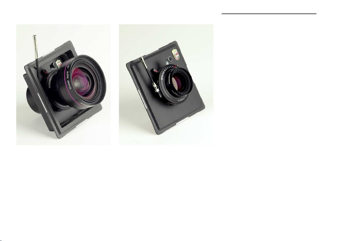
Apo-Sironar-digital HR 4,5 / 28 mm in Copal shutter
on recessed M 679 lensboard (001176) with cable
release extension.
Apo-Digitar-Makro 5,6 / 120 mm in Copal
shutter on flat lensboard (001160) with cable
release extension.
Photographers who have so far worked with
larger formats should note that in medium
format photography identical focal lengths
produce different results.
240 mm of the format 6x7 cm corresponds
to a focal length of 450 mm when using the
format 4x5 in. whereas a 120 mm lens is
already a long focal length for the digital format
37x49 mm. Medium format photographers
should know that lenses for images taken with
adjustable cameras will need a larger image
circle than those designed for non-adjustable
medium format cameras. Only lenses with large
image circles permit camera displacements.
The angle of view is the key of different lens
designs.
When using the rapid change adapter slide
for „stitching“ images you have to control
the image circle necessary for such multi
exposures.
MAIN LENS CHARACTERISTICS
Focal length, aperture, size of shutter, diameter
of filter (screw-in filter or slip-in filter) and
image circle. For details please refer to the
Linhof product and price listing or contact the
lens manufacturer.
30
Page 30
3. Le nse s an d S hu tte rs
3.1. LENS SELECTION
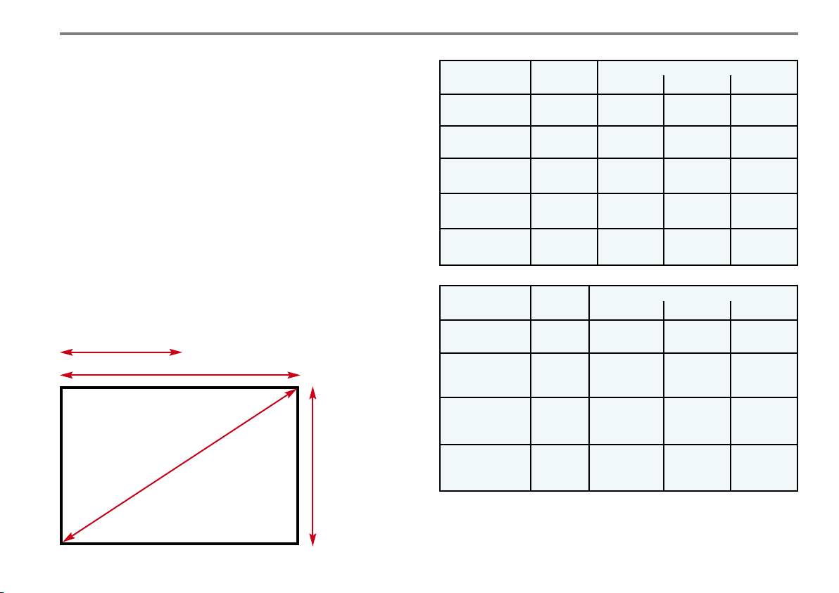
As a general rule, three different lenses are considered the minimum in
order to exploit the creative possibilities offered by cameras with adjustment facilities. The format diagonal of the picture format corresponds to
the normal focal length (see sketch). The tables show the possible lens
combination for the corresponding format.
For special applications also makro lenses 1 : 4 to 4 : 1, enlarging lenses
or repro lenses can be used.
The new generation of digital lenses offer a specially high resolution
necessary to produce optimum image information at small chip sizes in
digital imaging technique.
The table shows
the context of the
used picture for-
0,5 x long format side
= extreme wide angle
2 x long format side = long standard length
normal focal length
Format diagonal =
PICTURE FORMAT
mat, the format
diagonals and the
corresponding
focal lengths.
*Stitch: When
using the Rapid
Change Adapter
Slide the image
format and the
corresponding
image circle is
enlarged is enlarged.
short format side = wide angle
Picture Format
digital
Format
diagonal
Focal length
short normal long
30 x 30 mm 42 mm 24, 28, 35 45, 47, 55,6070, 72, 80,
90, 100
24 x 36 mm 43 mm 24, 28, 35 45, 47, 55,6070, 72, 80,
90, 100
63 x 36 mm
stitch*
72 mm 35, 45, 47 72 100, 120,
150
49 x 37 mm 61 mm 35, 45, 47 55, 60, 72 100, 120,
150, 180
71 x 49 mm
Stitch*
Picture Format
analogue
6 x 6 cm 85 mm 35, 38, 45,
6 x 7 cm 91 mm 35, 38, 45,
86 mm 35, 45, 55,4772, 80, 90,
100
Format
diagonal
Focal length
short normal long
72, 75, 80,90100, 120,
47, 55, 58, 65
75, 80, 90,
47, 55, 58,
100
120, 150,
180, 210
135, 150
120, 135,
150, 180
65, 72
6 x 8 cm 100 mm 35, 38, 45,
47, 55, 58,
65, 72, 75
6 x 9 cm 108 mm 35, 38, 45,
47, 55, 58,
80, 90, 100,
120
90, 100,
120, 135
120, 135,
150, 180,
210
150, 180,
210, 240
65, 72, 75, 80
The Linhof price and product listing contains the complete range of
currently available lenses. For further details you should contact your
Linhof experts.
31
Page 31
3. Le nse s an d S hu tte rs
3.2. IMAGE CIRCLE
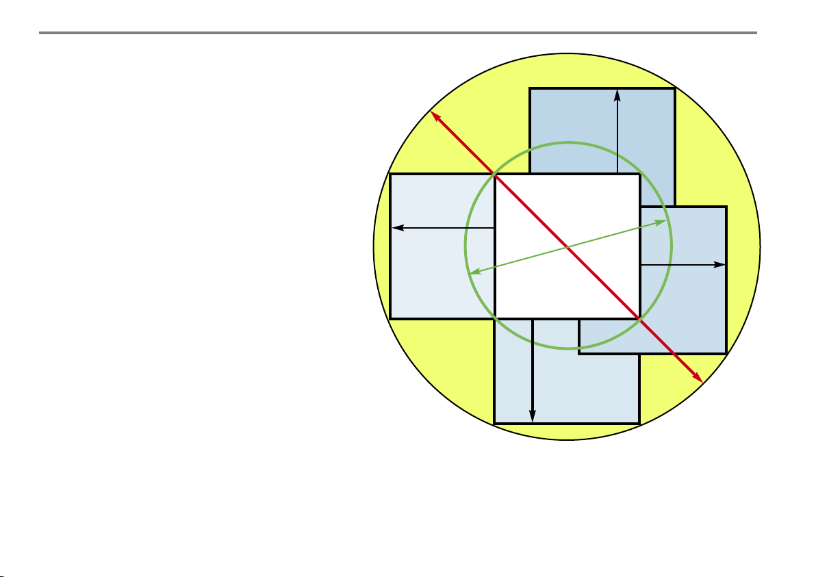
In order to make optimum use of the decisive
advantage of the M 679cs, i.e. its wide range of
displacements lenses are needed with large
image circle and first-class image reproduction
quality right up to the edge of the image circle.
The most important camera displacement is the
parallel adjustment to eliminate or reduce converging verticals. For this, the lens must have an
image circle far beyond the size of the taking
format.The image circle stated in the technical
specifications of the lens manufacturers always
refer to a focusing distance of infinity and a
working aperture of f/22. For shorter distances
(e.g.for table shots), the image circle diameter
will increase so that even larger adjustments are
required. For digital lenses the the corresponding working aperture is referred as f/11.
The Linhof M 679cs offers the necessary long
mechanical adjustment facilities.
Please always ensure that the image circle of
the lens covers the mechanical displacements.
As a practical hint: when looking through the
lens onto the groundglass at working aperture
all four edges of the picture format have to be
visible.
Shift limits
Image circles and shift limits.
Within the limit of a sufficiently large image
circle the picture format can be displaced.
Ima
Picture format
f
r o
te
me
ia
d
le
s
n
irc
c
le
e
t
g
rma
m fo
iu
d
me
Shift limits
I
ma
of
g
e
v
i
c
e
i
w
r
c
c
l
e
a
me
di
a
r
me
a
l
t
e
e
ns
r
32
Page 32
3. Le nse s an d S hu tte rs
2.3. LENSBOARDS
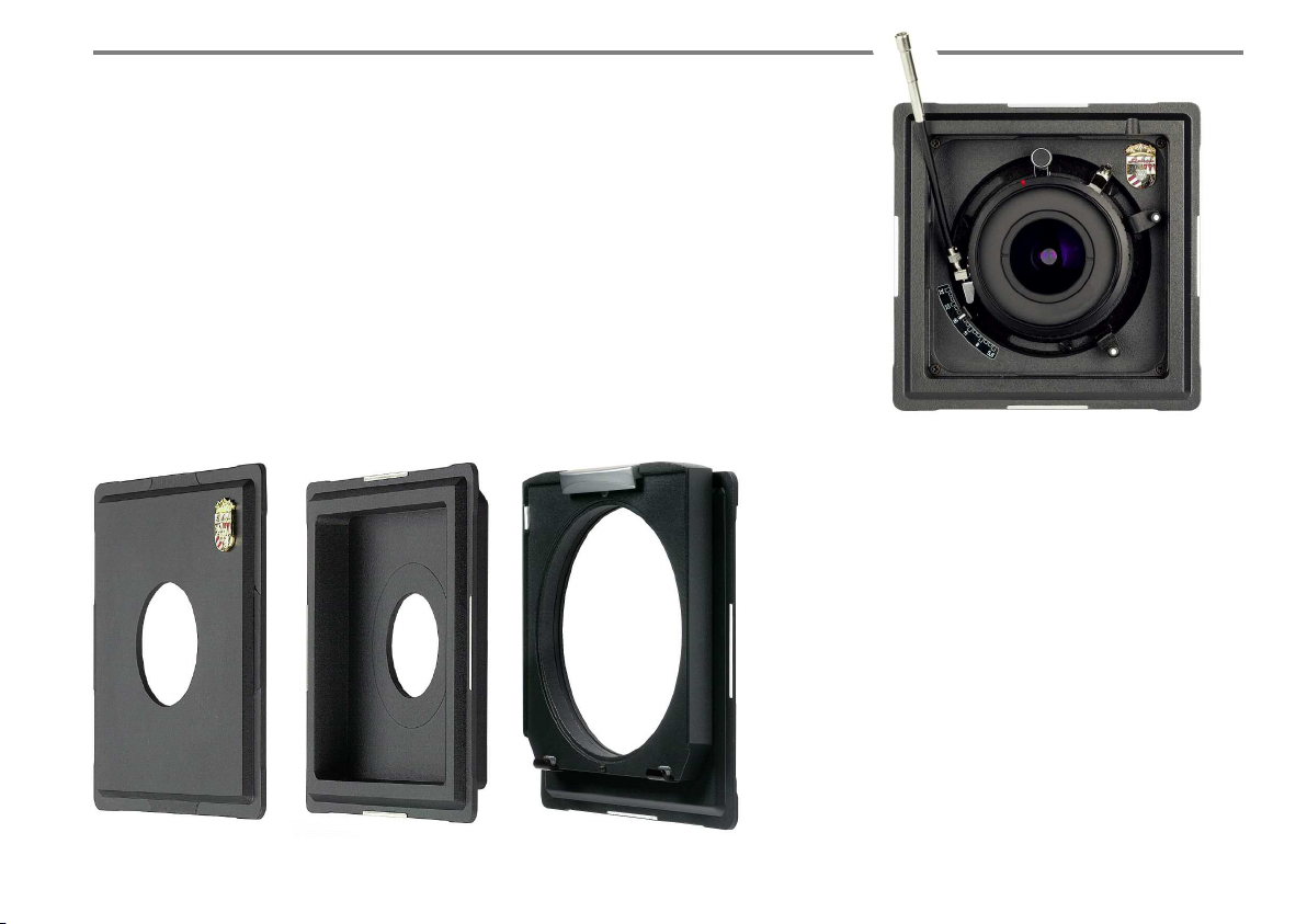
The lensboards of the M 679cs are square
accepting the lens exactly in the centre.
According to focal lengths and lens design
different lensboards are offered, flat or recessed
with different holes corresponding to the required shutter sizes.
Left: flat lensboard, center: recessed lensboard,
right: lensboard adapter for Technika 45 lensboards
(001100)
With all symmetrically designed lenses (normally with lenses longer than 90 mm) the adjustment of the lens standard is effected by
swinging around the principle point of the lens
thus avoiding any movement of the picture.
For the use of lenses already mounted on
Technika 9x12 lensboard a special lensboard
adapter is offered with the M 679cs.
4x Recessed Lensboard for
Apo-Digitar XL 5,6/35 in Copal Shutter
This lensboard (001178) allows the use of the
5,6/35 mm lens in Copal shutter with the
Linhof M 679cs including the Rapid Change
Adapter Slide. The decisive advantage is the
availability of an increased omni directional
shift range of 12 mm.
Despite of the depth of the recessed board an
easy and comfortable shutter operation is provided thanks to the re-arrangement of the
release lever and aperture scales.
33
Page 33
3. Le nse s an d S hu tte rs
3.4. SHUTTERS
The shutter of a lens controls the exposure,
i.e. aperture and time.
We offer all lenses in central mechanical and
electronically controlled shutters which can
also be mounted by Linhof on the corresponding lensboards.
Mechanical Copal shutters
Central shutters with stepless adjustment or
adjustment in increments.
Copal size 0: 1 – 1/500s + B + T
Copal size 1: 1 – 1/400s + B + T
Electronic shutters
Electronically controlled shutters enable easy
control via computer software thus utilizing all
features of one-shot or multi-shot digital backs.
These electronic shutters offer considerably
more „increments“ for aperture and controlled
time exposure.
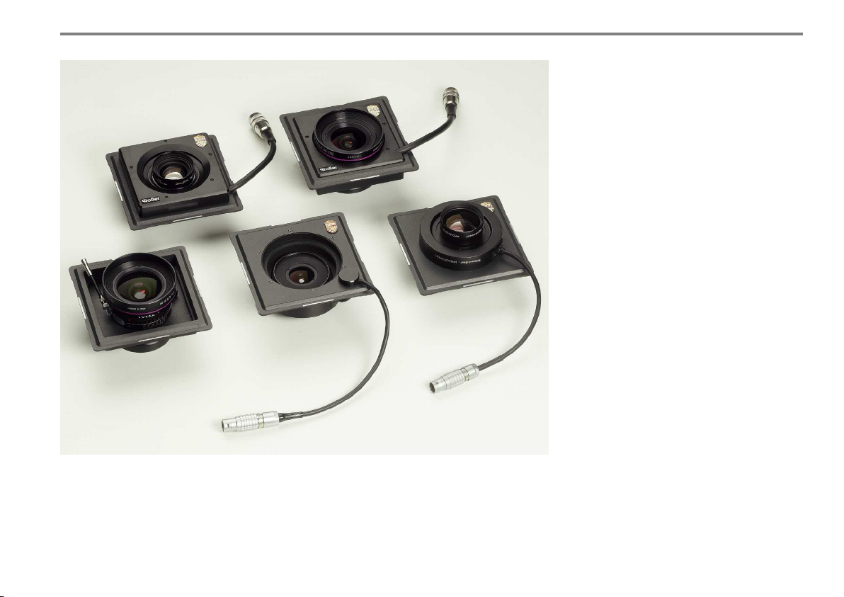
The Rollei electronic view camera shutter
Electronically controlled via remote control
Rollei LensControl S. Sizes 0 an 1.
Shutter speeds B and 30s to 1/500s in third-stop
increments.
In tenth-stop increments adjustable 5-blade-iris
aperture. Weight 306 g.
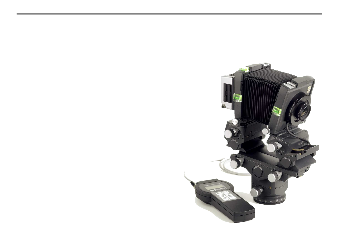
Schneider Electronic shutter
This is electronically controllable via the
computer. Size 0. Shutter speeds B and 32s
to 1/60s in tenth-stop increments adjustable
5-blade-iris aperture. Weight 180 g.
Schneider electronic
shutter and shutter control
with Linhof M 679cs and
digital back.
34
Page 34
3. Le nse s an d S hu tte rs
3.5. DIGITAL LENSES
The lens is an important link of the quality
chain in professional photography.
Digital lenses adjusted to the needs of digital
imaging technique offer optimum sharpness
fully utilizing the high resolution chip sensors.
These lenses meet high quality requirements
concerning contrast , correction of distortion
and absence of color fringes.
New digital wide angle lenses with image
circles from 60 to 110 mm have the capacity
for adjustment, correction of perspective, „converging lines“ as well as for depth of field control according to the Scheimpflug law.
For close-up and makro photography there exist
special makro lenses optimized for a 1 : 1 and
higher reproduction ratio.
The full range of available digital lenses can be
found in the current Linhof price and product
listing.
Digital lenses on Linhof M 679 lensboards ranging from 24 to 210 mm
focal lengths in electronic or mechanical shutters ( Rollei, Schneider, Copal).
35
Page 35
4. C A MER A ADJU STM E NTS
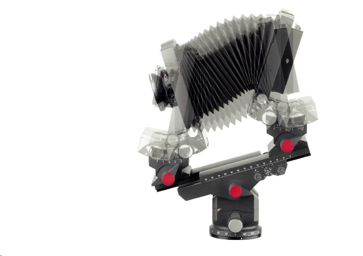
Only by the possibility of displacing lens and
rear standard all advantages of a view camera
are fully utilized. These displacements serve for
control of perspective, positioning of the depthof-field and creative image composing.
Any camera displacement requires the appropriate lens with the sufficient image circle.
Before starting to use camera movements,
return all camera controls to zero.
36
Page 36
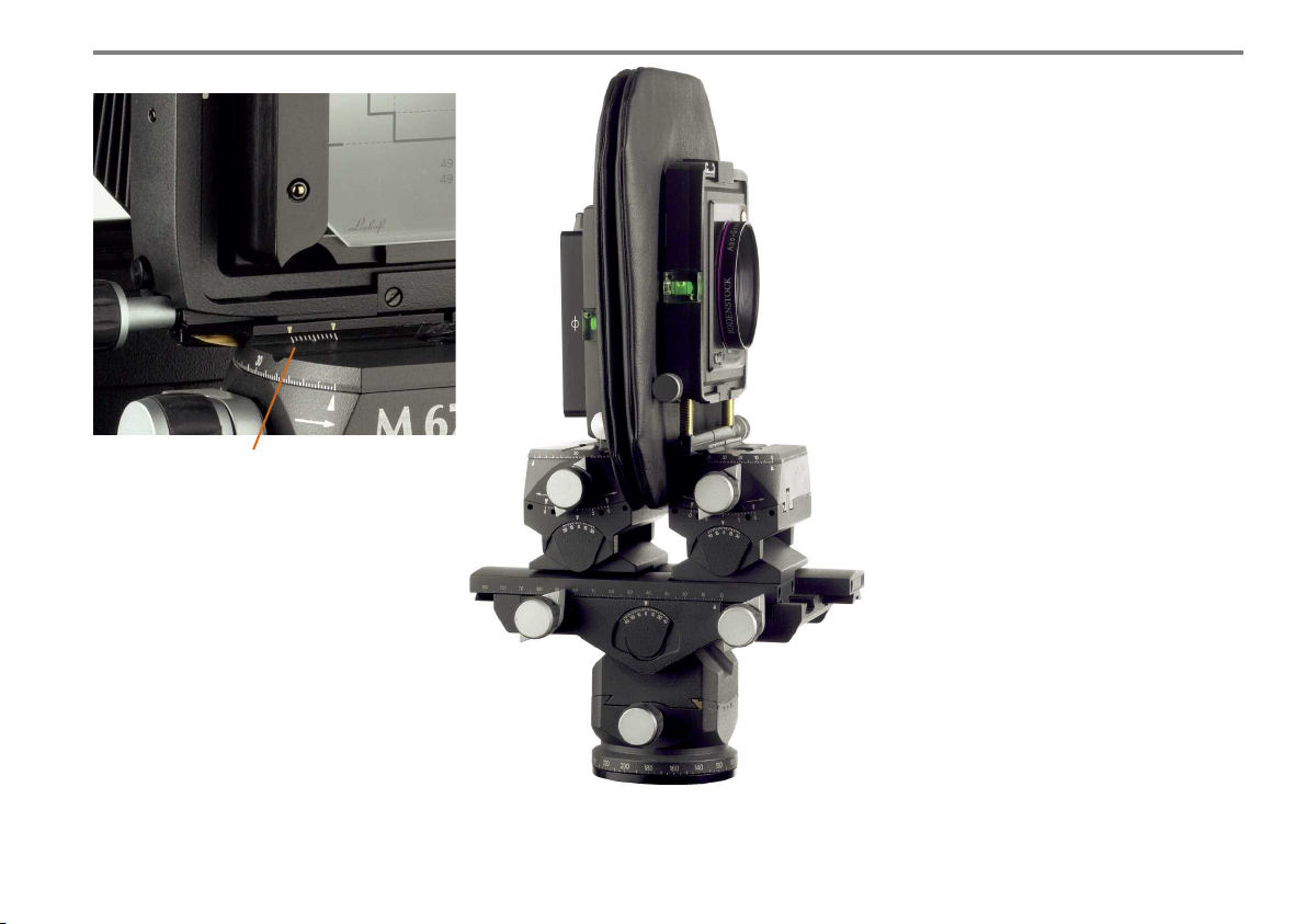
Scale for lateral shift at the rear standard
4. Ca mer a Ad j us tme nts
4.1. VERTICAL AND LATERAL SHIFT
(DIRECT DISPLACEMENT)
Horizontal and vertical parallel displacements
are operated with self-aligning micro drives.
Direct adjustments are recommended for precise cropping corrections and should normally be
made after having finished all settings thus
avoiding any movement of the tilting axis out of
their centre position .
When working with extremely short lenses (24,
28, 35, 38 mm ) we recommend the direct
camera displacement using the horizontal and
vertical shift facilities. In general their range of
adjustment is sufficient and all displacements
remain parallel.
Direct parallel adjustment
(vertical shift) with self
aligning micro drives at the
lens standard (M 679cs with
Apo-Sironar 4,5/35 mm and
wide angle bellows).
37
Page 37
4. Ca mer a Ad j us tme nts
4.2. INDIRECT PARALLEL DISPLACEMENTS
Parallel movements (rise and shift of the front and back standards) are
primarily used to eliminate converging verticals or horizontals in subjects
with predominantly parallel lines. While vanishing lines are simply the
normal perspective rendition resulting from an oblique position of the
image plane relative to the main subject plane, the experienced professional will see that through proper use of camera adjustments pictures do
not show any of the unwanted perspectives so often found in architectural
and industrial subjects.
Whether up, down or lateral shift of the lens or rear standard:
Most parallel adjustments are executed indirectly.
In other words:
The front and rear standard is simply placed parallel to the main
view of the subject.
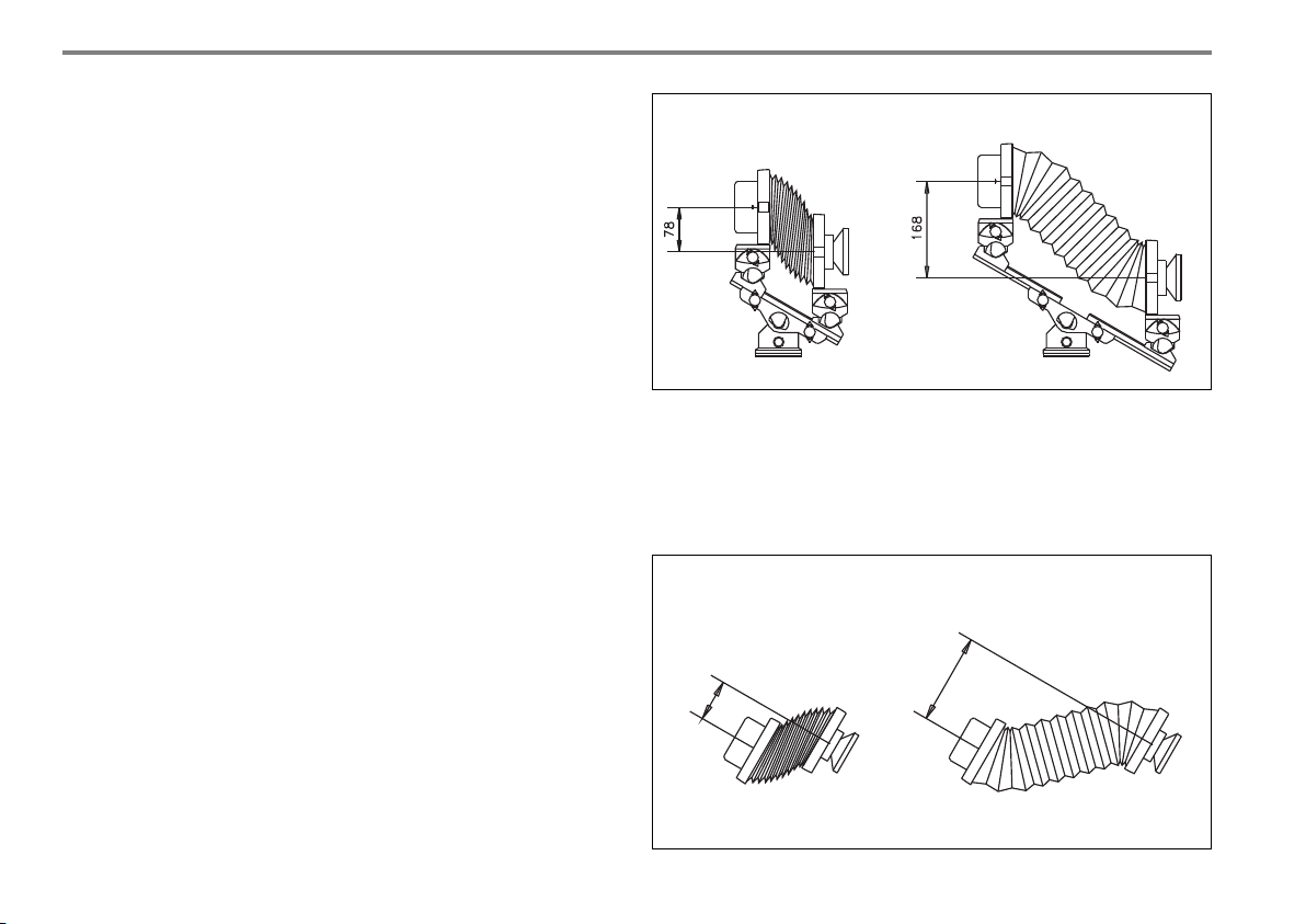
vertical parallel shift
The possible adjustments increase linear with the camera extension. The M 679cs
offers an up/down or lateral shift of 168 mm each at maximum camera extension
(tilting angle 30°). At minimum camera extension the possible indirect parallel
shift is approximately 38 mm. The sketch shows extension and adjustment which
can be achieved with normal bellows.
horizontal parallel shift
(view from above)
38
Page 38
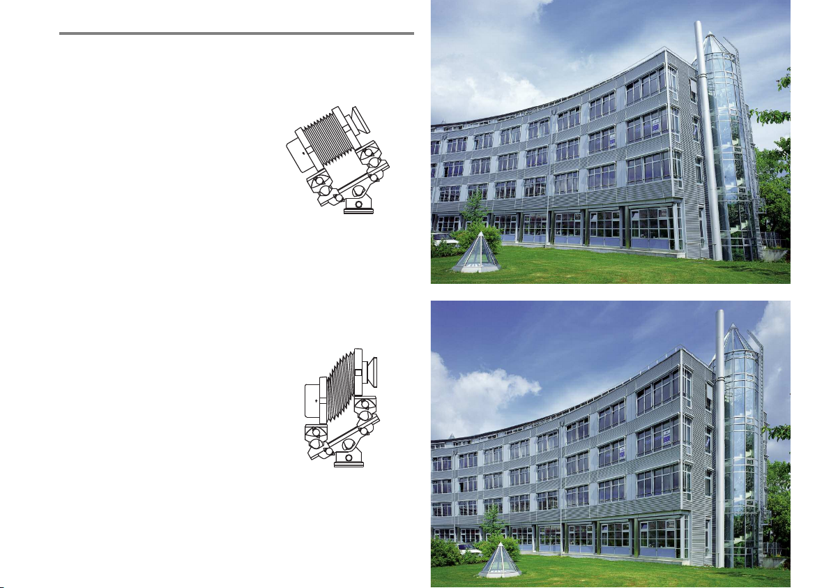
4.3. VERTICAL PARALLEL SHIFTS
(INDIRECT)
Indirect vertical shifts (lens rise or lens
drop) are used to produce an image without converging lines when shooting from
a low or high view point.
LENS RISE:
With all adjustments in neutral position
and with the aid of the integrated panorama benchholder the camera is set to the
subject. Focus until the object appears in
focus on the groundglass. Adjust lens and
rear standards to vertical with the aid of
the spirit level. If necessary, refocus.
The picture was taken with a 58 mm
wide angle lens.
4. Ca mer a Ad j us tme nts
1. Set the camera to
the subject,
composing the image.
2. Adjust lens and rear standards ti vertical with the
aid of the spirit level, if
necessary make cropping
correction, focus.
Page 39
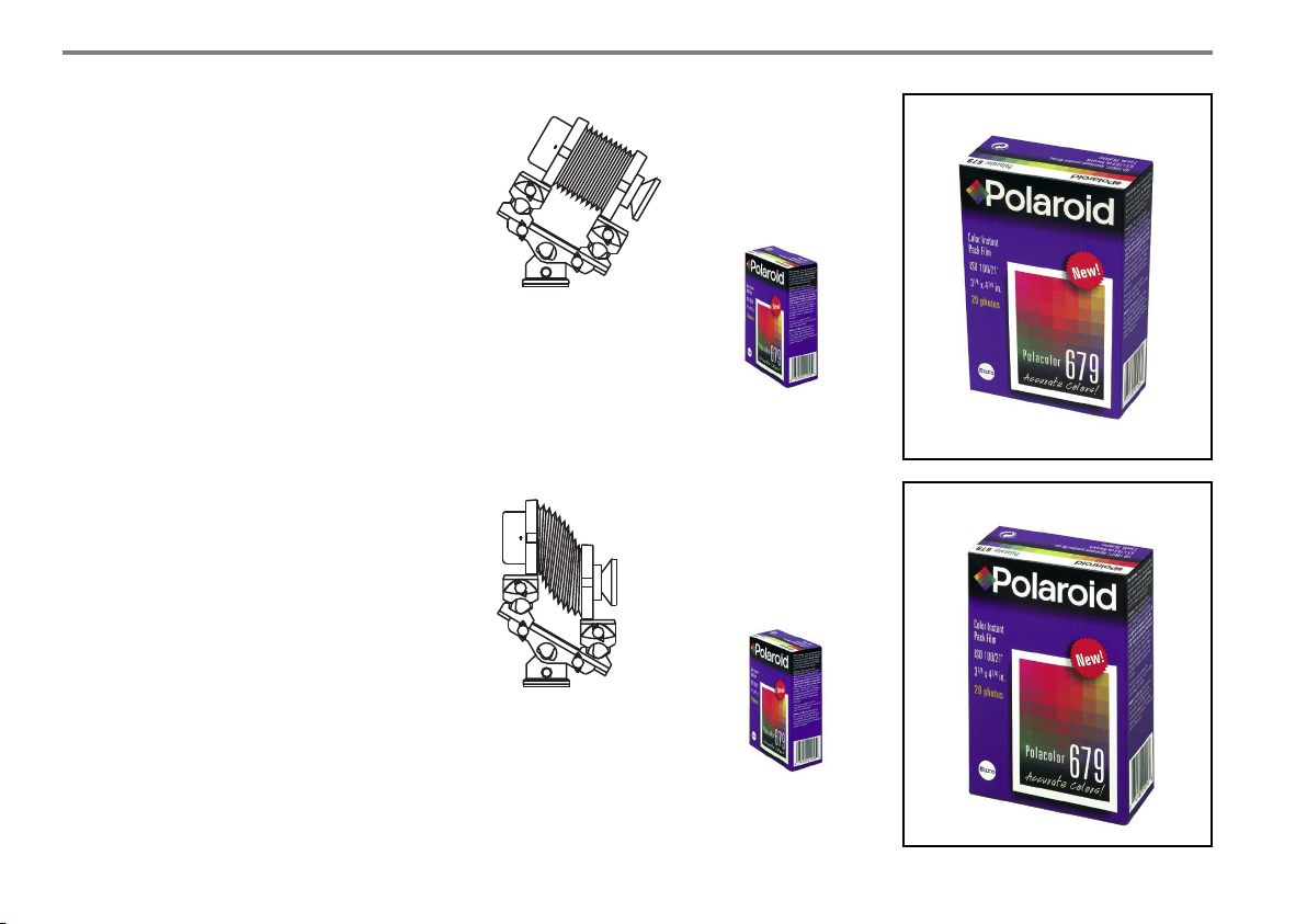
4. Ca mer a Ad j us tme nts
LENS DROP
When working in the studio shooting is often
made from a high view point (still life, tabletops etc.): with the aid of the integrated panorama benchholder the camera is set to the subject
determining the image on the groundglass and
focus. Adjust front and rear standards to vertical
with the aid of the spirit level, refocus.
REMAINING PERSPECTIVE
Since totally corrected images can sometimes
appear unreal a so-called "remaining perspective" is often desirable. This is an uncomplicated procedure: read off the angle of tilting of the
optical bench and reduce the base tilt of the
standard by approximately 25%.
40
1. Set the camera to the object,
frame the image.
The package is seen with
converging verticals.
2. Adjust front and rear
standard to vertical with
the aid of the spirit level.
The package is seen with
undistorted verticals.
Page 40
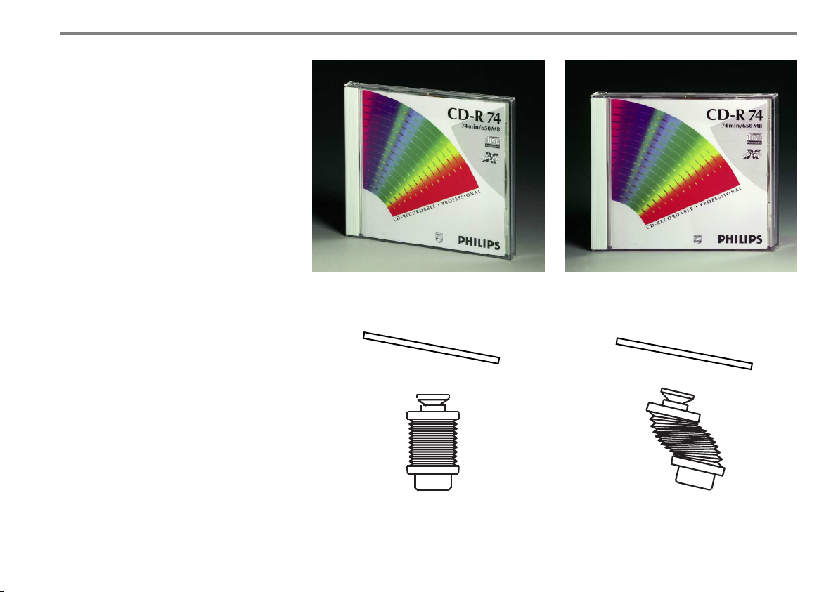
4.4. HORIZONTAL PARALLEL SHIFTS
Horizontal shifts (lateral displacement or cross
front movements) are used to obtain frontal
views from a lateral camera position, producing
an image without vanishing lines and perspective distortion. This is a common requirement
when standing in front of reflecting surfaces
(mirrors, windows) or when the view from a
centre position directly in front of the subject is
obstructed or includes unwanted subject matter. To ensure correct perspective, start by placing the camera (and the filmplane) parallel to
the main object plane:
The camera has to be rotated with the bench
panorama holder to the object until reaching
the desired framing on the groundglass. Then
turn the back standard around the vertical axis
until you reach the main view of the object preferably utilizing the grid lines of the groundglass. Now transfer the angle of rotation of the
panorama of the rear standard to the lens standard for obtaining exact parallelism.
1. Shooting with non-displaced camera:
the main view shows converging lines.
4. Ca mer a Ad j us tme nts
2. Shooting with camera and parallel adjustments:
the main view is seen undistorted.
1a. Set camera to the object, frame the image
(camera is shown from above).
2b. Adjust rear standard parallel to main view.
Transfer angle to lens standard.
41
Page 41
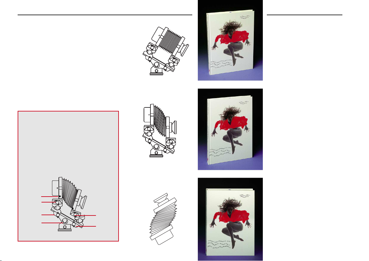
4. Ca mer a Ad j us tme nts
4.5. COMBINED PARALLEL SHIFTS
Horizontal and vertical shifts can, of course,
also be applied in combination.
A typical example is the reproduction of a
package where the front cover is to be shown
as a rectangle and both the top and the side
should be visible as well.
PRACTICAL HINT:
All camera adjustments should start at the panorama benchholder (1). Then follows - if necessary - the adjustment of the standards to vertical. All control elements are situated above the
panorama benchholder at the optical bench (2).
The final adjustment facilities (level 3) for the
camera are swings and tilts by rack and pinion
drives. Finally the cropping correction is made
(4).
4
3
2
1
3
2
1. Select the appropriate
camera view point, adjust
the groundglass, determine
framing.
2. Adjust both standards
vertically with the aid of the
spirit level for avoiding converging lines.
3. Swing rear standard for
parallel position to the book
cover. Set camera to grid net
lines of the groundglass. Read off
angle and transfer to the lens
standard. Refocus (illustration
shows camera from top).
Make cropping correction when
necessary.
42
Page 42
4. Ca mer a Ad j us tme nts
4.6. SCHEIMPFLUG ADJUSTMENTS
When talking about camera movements, the
term "Scheimpflug" is often subject to a certain
amount of misinterpretation. Even by experienced photographers, the use of Scheimpflug
adjustments to control focus and depth-of-field
is either looked upon as a highly complex
mathematical problem or considered a simple
adjustment procedure which a modern view
camera should do more or less automatically by
itself. Neither opinion really corresponds with
the photographic practice, as the truth is somewhere in the middle, but once there is a certain
understanding of the theory behind all Scheimpflug adjustments, their practical application
becomes as simple and fool proof routine.
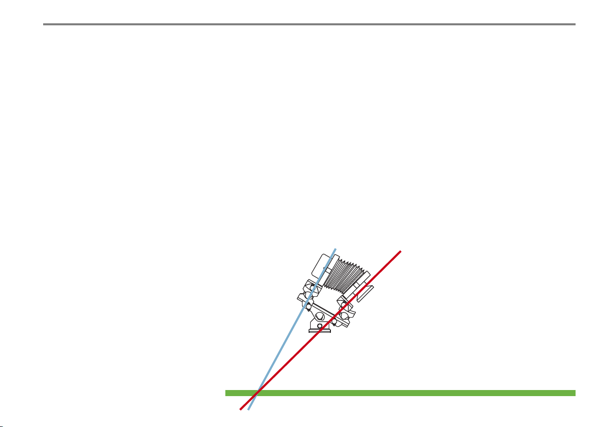
THE SCHEIMPFLUG RULE
To provide sharp focus over the entire picture
when main object plane is at an angle to the
camera, the object main plane, the lens plane
and the image plane must intersect in one
common line.
This rule can be applied by swinging the
groundglass or (and) the lens standard.
Scheimpflug by swinging the lens standard does
not alter the given perspective "consuming"
however much of the image circle (limits of the
adjustment possibilities). Groundglass-Scheimpflug exaggerates the perspective rendition but
"saves" image circle.
PRACTICAL PROCEDURE
Before starting with any Scheimpflug adjustments, the plane of sharp focus running from
the near to the far object point should be determined. The most simple application can be
found with two dimensional objects, such as
plane of table, carpet, meadows or wall: the
main object plane has a certain angle to the
image plane. First determine one near object
point and one far object point of the object
plane. Near and far object point should be seen
image plane
lens plane
object main plane
(for example plane of table, carpet, meadows)
on the opposite side of the groundglass. The
amount and direction to any camera adjustment
required to fulfill the Scheimpflug condition can
easily be determined by looking at the camera
and the subject from the side. It will be seen that
the more distant objects in the infinity range
(buildings) require relatively small adjustments
of a few degrees which will steadily increase
with closer focusing distances. In extreme closeup work, with reproduction ratios between 1:4
and natural size 1:1, the amount of swings or
tilts needed will often require the adjustments of
both the front and the rear standard (for instance
small table-top subjects, tools, electronic components and assemblies etc.).
43
Page 43

4. Ca mer a Ad j us tme nts
DISPLACEMENTS, WHERE?
The M 679 with its highly practical centre rotation of the lens standard, also allows direct
Scheimpflug adjustments with the front simply
by focusing to the near object point and swinging/tilting the lens standard until also the far
object point comes into focus. As a result of the
centre rotation, only a slight focus adjustment
will become necessary.
Displacement with rear standard:
+ only slight focusing necessary
+ desired plus of perspective rendition
+ centre raise of the lens are used: positive for a
clear quality of the image
+ extremely simple control of depth-of-field:
turning axis always remains in focus
– distortions unavoidable
– rays do not meet the groundglass centrally
thus complicating the viewing of the image
Displacement with the lens standard:
+ no perspective distortion
+ easy viewing of the image
on the groundglass
– refocusing necessary during
adjustments
– border rays of the lens will be used,
i.e. the limit of the image circle is
quickly reached.
Vignetting is possible
DOUBLE SCHEIMPFLUG
There are many objects where the desired sharpness is in an oblique plane. In this case, both
axis - the vertical and the horizontal axis - have
to be swung.
First swing the horizontal or lateral axis, then
swing around the vertical axis in order to avoid
any yawing.
By swinging of the image and lens plane any
desired focal plane can be achieved.
44
Utilizing the advantages of both procedures:
1. Displacements with the rear standard - centre of ground-
glass remains in focus.
2. Angle value is transferred to lens standard (reduced by
angle value of adjustment in per cent values), swing in
opposite direction, refocus.
Displacements with
rear and lens standard:
Tilting at the horizontal
axis
Displacements with
rear and lens standard:
swinging around the
vertical axis (illustration shows camera from
above).
Page 44
4. Ca mer a Ad j us tme nts
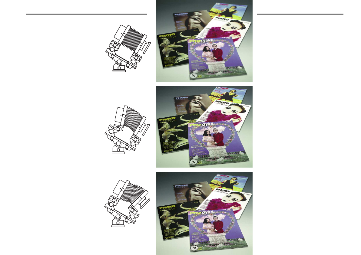
PPRACTICAL EXAMPLE
The design of the M 679cs permits
turning and swinging of the lens in
the principle point (focal length
over 90 mm). Tilting and swinging
of the groundglass is made exactly
in the horizontal and vertical axis.
This design therefore permits the
easy use of the Scheimpflug rule
(the example shows a typcial still
life situation in the studio).
This systematic operation can, of
course, be facilitated by starting to
swing the lens standard. In this
case, however, continue as refocusing is necessary.
1. Set the camera with the panorama benchholder to the object. If possible focus an
object point (M) on the groundglass axis
(swinging axis) which should be in the
desired focal plane.
2. Now, swing rear standard toward the
expected direction until the near and far
point become simultaneously sharp
(N + F both in the desired plane).
The Scheimpflug adjustment is made.
The plane of sharpness runs from the
foreground to the background.
But the foreground is still distorted.
3. Whilst maintaining the perspective
rendition the tilting angle of the rear
standard is transferred to the lens standard
reduced by the percentage of angle value.
For example: the tilting angle of the rear
standard is 18°, minus 18% of 18 (approximately 3), results into the required angle
of the lens standard of 15°.
The rear standard will then be reset to
zero. Finally, refocus.
4545
Page 45
4. Ca mer a Ad j us tme nts
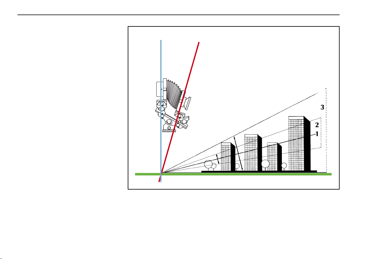
4.7. DEPTH-OF-FIELD WEDGE
Since the objects to be handled are normally
3-dimensional you have to use additionally a
small lens aperture.
Example: The height of a building is the area
of the required depth-of-field. In order to reach
this position with the smallest possible lens
aperture the focal plane is set in such a way
that the object is intersected in the centre as the
depth-of-field zone, which extends to either
side of the plane of focus, increases uniformly.
The area of the depth-of-field is like a wedge.
This will become smaller when being nearer to
the camera. Table-top shooting with increased
depth-of-field necessitate placing flat objects
near to the camera whereas higher objects
should be placed in a more distant position of
the camera. Most still lifes are typical examples.
1 Plane of focus
2 Depth-of-field wedge
at full aperture
3 Depth-of-field wedge with
stopped-down lens
46
How to gain depth-of-field
As the depth-of-field zone, which extends to either side of the plane of focus, increases uniformly when the
lens is stopped down, it is important to adjust the camera in such a way that the plane of focus runs through the
middle of the object. Since the depth-of-field increases at same aperture with increasing distance from the
camera, a wedge type area for the sharpness is the result.
Page 46
4.8. SUMMARY
1. Use Scheimpflug adjustments for depth-of-
field control only for subjects which are in
an oblique position to the camera from the
near point to the far point.
2. Without stopping down only 2-dimensional
subjects (carpets, walls etc.) will have an
overall sharpness.
3. Scheimpflug adjustments are a logical way
to control depth-of-field as long as there is
one major and clearly defined plane of
focus.
4. If overall sharpness over an expanded
3-dimensional space without clearly defined sharpness planes is required, this can
only be achieved in the conventional way
through a correspondingly small lens aperture as determined by a suitable depth-offield calculator.
4. Ca mer a Ad j us tme nts
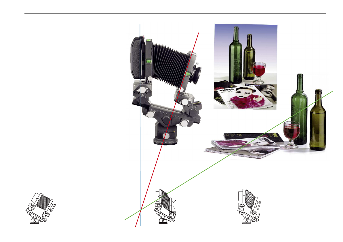
Typical studio situation
With the aid of the
integrated panorama tilt
head the camera is set
to the object.
1
To avoid converging
vertical details lens
and rear standard are
adjusted to vertical
with the aid of the
spirit level.
2
Scheimpflug for increased
depth-of-field. In this case,
the lens standard has to be
tilted. Use micro drives for
direct vertical and lateral
shifts. Determine depth-offield and aperture with the
aid of the depth-of-field
optimizer.
3
47
Page 47
4. Ca mer a Ad j us tme nts
4.9. DEPTH-OF-FIELD AND
DEPTH-OF-FIELD OPTIMIZER
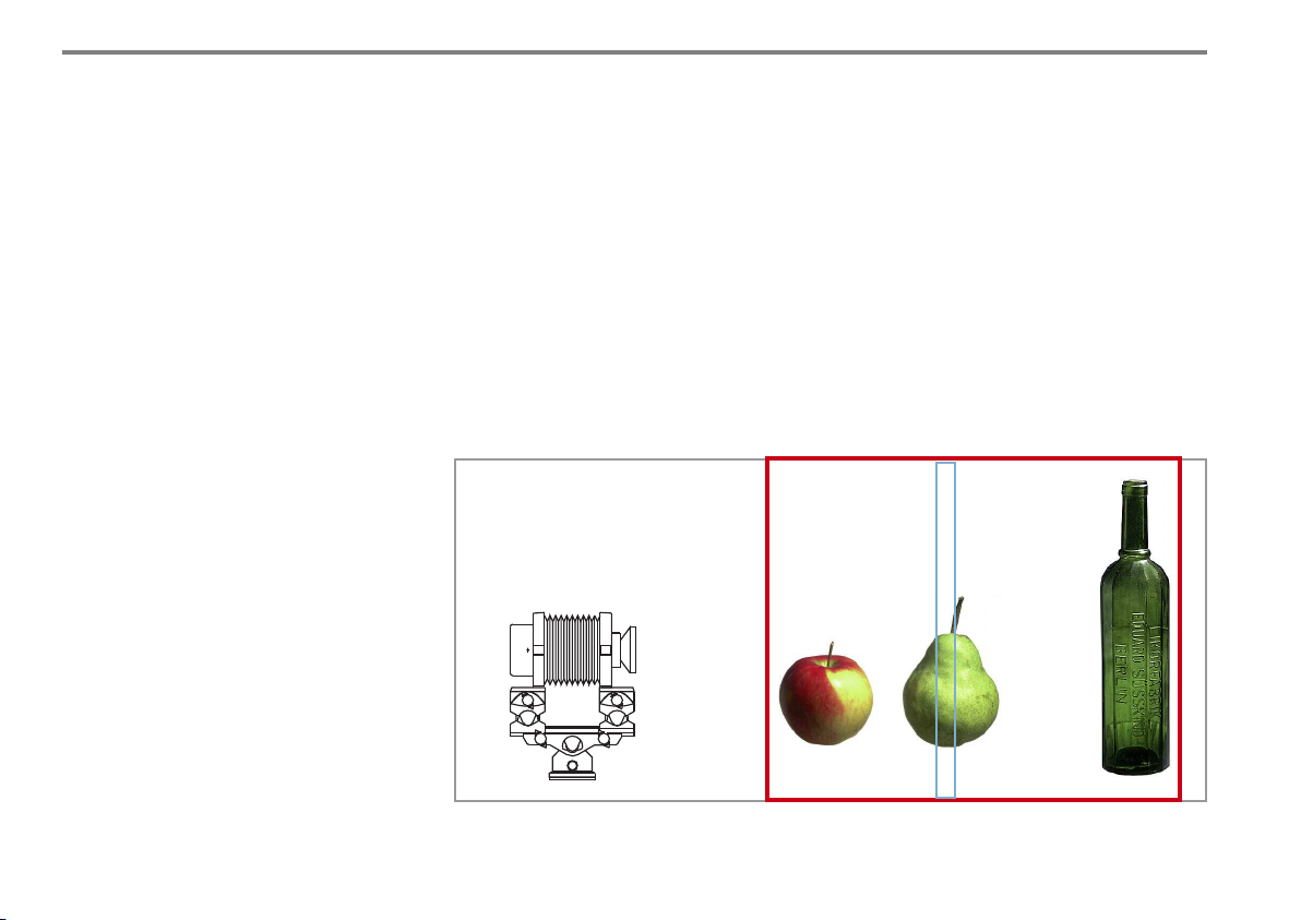
Generally speaking, only one plane can remain
sharp. Everything behind or before becomes
increasingly unsharp. The area the photographer is not visualizing this sharpness is called
depth-of-field. This depth-of-field is based on
the following factors:
1. Reproduction range.
The smaller the reproduction range,
the larger the depth-of-field area.
2. Stopped-down lens.
The more the lens is stopped down, the
larger is the depth-of-field.
Please observe that the physically given
defraction of the lenses result into a decrease of the lens performance. Therefore,
never stop down too much if unnecessary.
The general rule for the ideal point of focus
with a desirable depth-of-field zone is: Focus
on 50% of the difference of the camera extension, i.e. on the middle between near and far
point focusing of the camera.
Depth-of-field optimizer
The M 679cs offers an integrated depth-of-field
optimizer. For the depth-of-field optimizer,
interchangeable format dials are available:
• Format dial 3x3 for digital backs,
chip size from 24x26 to 37x49 mm
• Format dial 6x7 for formats 6x6 – 6x8 cm
(included in camera price)
• Format dial 6x9 cm
Depth-of-field at
stopped down lens
If the optical bench is tilted more than 20°
the calculated aperture value can be reduced
by 1/3 f/stop.
If the depth-of-field requirements result in an
excessively large extension difference, try to
reduce the distance by re-arranging the
depth-of-field zone using Scheimpflug adjustments. Sometimes it is necessary to increase
the taking distance to eliminate or reduce
depth-of-field problems.
Depth-of-field at
full aperture
48
When stopping down a non-displaced camera the depth-of-field increases more
in the background than in the foreground depending on distance and aperture.
Page 48
3. Ca mer a Ad j us tme nts
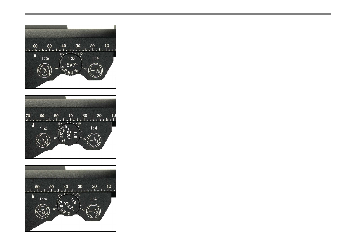
Here is how it works:
1. Focus on the most distant subject point, rotate
format equivalent dial triangle on triangle to
basic position (illustration shows format 6x7).
2. Focus on the near point of the subject
(triangle in the illustration = 6).
Read off the working aperture on the dial opposite to the triangle (here 45) and set the lens
accordingly. The optimizer is calculated for a
reproduction range of 1 : 8.
Reproduction range 1 : 4 = + 1/3 stop (32 2/3),
1 : infinity = – 1/3 stop (45 1/3).
3. Refocus to half of the extension value
shown or 2 f stops (triangle in the
illustration = 3 or f 22).
Lock integrated lever of focusing knob.
The optimum sharpness is found.
CLOSE-UP FOCUSING
Focusing of studio cameras is normally handled
with the rear standard. However, a reproduction range of 1:1 requires enormous displacements even for smaller depth-of-field operations. In this case, focusing with the lens standard is strongly recommended which changes
not only the front focal distance but also the
image distance (increasing focal distance =
diminishing image distance and vice versa).
By doing this, focusing is faster with less movements. Thanks to the adjustment technique by
identical rack and pinion comfort and identical
precision micro drives and clamping elements
for both standard rails the Linhof M 679cs fully
supports this technique. Only the final focusing
on the most distant subject point and the near
point of the subject for finding of the optimum
aperture at the aperture dial is effected with
the back standard.
49
Page 49

4 Cam era A dj u st men ts
4.10. WHAT ABOUT YAWING
Yaw can occur when a camera system does not
allow the photographer to adjust the standards
to a vertical position after inclining the monorail. In this case yawing occurs with indirect
displacements and the use of the Scheimpflug
rule, with the result that one or both standards
swung around their axis in a non-vertical position, reduce the sharpness, and adjustments
already made cannot be fully utilized.
The design of the Linhof M 679cs will always
avoid yawing when correctly handled: with
indirect up and down shifts, tilted base and vertical standards, the standards will always
remain vertical. When adjusting according to
the Scheimpflug rule such as tilting or turning
the lens around the center axis the depth-offield zone will always be clearly defined and
controlled.
When utilizing double Scheimpflug with the
M 679cs the rule is: right before left.
This means: first tilt the horizontal axis with the
aid of the micro drives situated on the right
side. Then rotate around the vertical axis.
The operating elements are now on the left side
of the camera (seen from the groundglass).
This sequence is also necessary for lateral indirect parallel displacements and necessary
Scheimpflug around the horizonal axis - first
finish your adjustments according to Scheimpflug, then adjust the standards to parallel.
50
Page 50
4. Ca mer a Ad j us tme nts
4.11. VIEW CAMERA MOVEMENTS
MADE SIMPLE
View camera adjustments become less complicated if you stick to a predetermined method of
operation taking into account the following
rules.
• Before starting to use camera movements,
return all camera controls to zero.
• Framing with the M 679cs is as easy as with
a non-adjustable medium format camera:
set the camera to the object.
If necessary: adjust lens and rear standard
to vertical with the aid of the spirit level or
swing the standards around the vertical
axis.
• If an image with parallel lines and right
angles is required: align camera/groundglass so that it is parallel to the
main subject front.
• Use Scheimpflug adjustments for depth-of-
field control, if necessary. Scheimpflug can
only help if one dimension of the subject is
dominating (for example flat tart). With
uniform bodies (for example ball, cube)
Scheimpflug will not necessarily be advantageous unless one plane is of priority.
• In the event that a shot needs to be
marginally re-framed after composition this
can easily be done by direct cropping
correction.
• Still missing depth-of-field can now only be
reached by stopping down of the lens.
• Focus precisely with the aid of the depth-
of-field optimizer calculating the necessary
aperture.
• If required depth-of-field cannot be ob-
tained, the reproduction ratio should be
changed by increasing the focal distance.
• Should a certain combination of camera
movements fail to produce the desired
effect, a solution will often be found by
returning all adjustments to zero and
repeating the above procedure.
• After any adjustment made precise locking
is required, however, do not clamp the
micro drives too extensively.
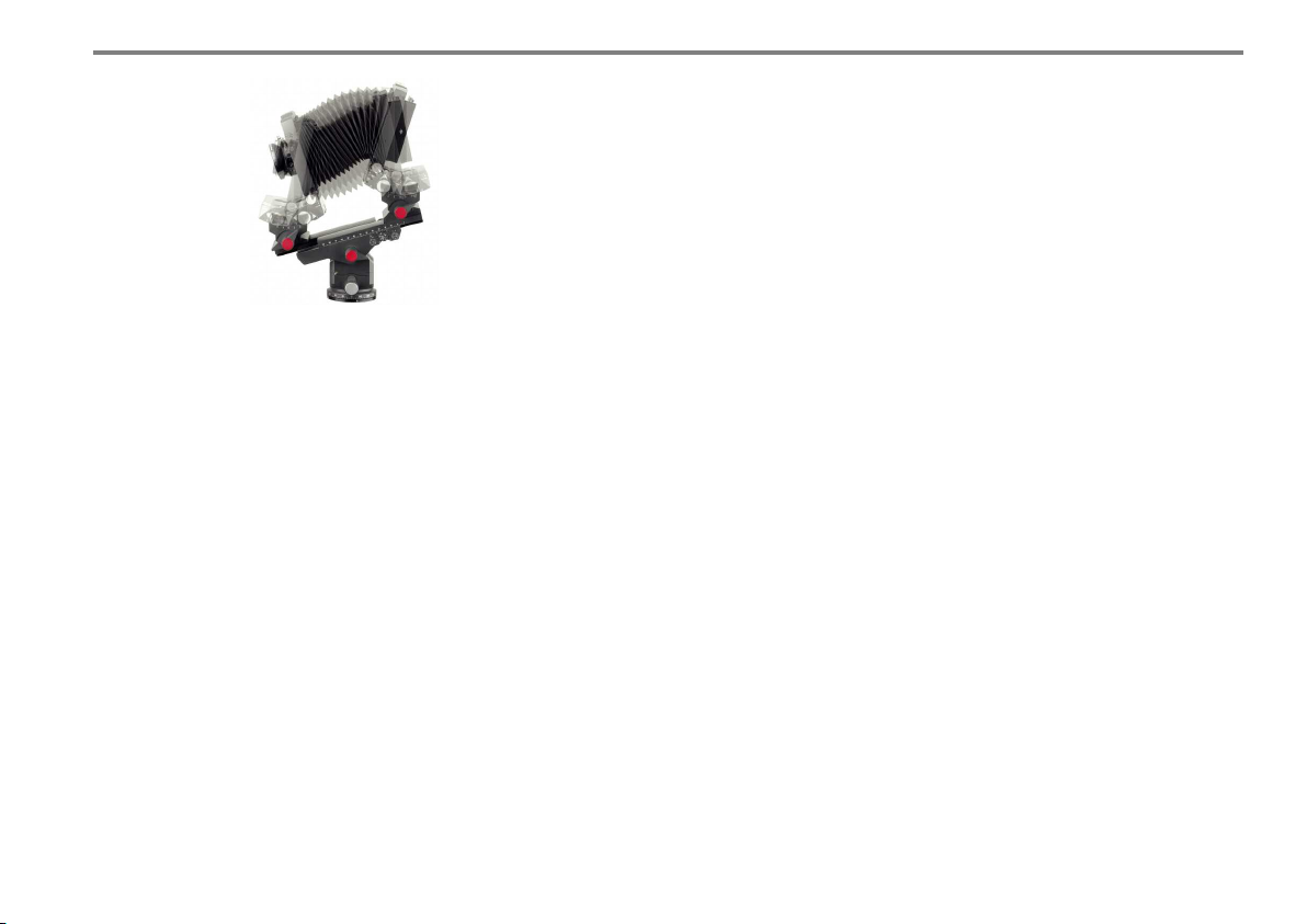
The red locking levers for panorama
benchholder and the standards should be
carefully tightened.
51
Page 51

LINHOF PRÄZISIONS-SYSTEMTECHNIK GMBH
RUPERT-MAYER-STRASSE 45
81379 MÜNCHEN
GERMANY
TEL. +49.89.724920
FAX +49.89.72492250
www.linhof.de
[email protected]
TECHNISCHE ÄNDERUNGEN VORBEHALTEN SPECIFICATIONS SUBJECT TO CHANGE 025105 / 0607 E
 Loading...