

Page 1
Installation Instructions for Lingenfelter
2007-2010 GM 2500 Suburban & Yukon XL
Auxiliary Fan System
(with AC clutch controlled fan output)
Revision - E
PN L300080607
Lingenfelter Performance Engineering
1557 Winchester Road
Decatur, IN 46733
(260) 724-2552
(260) 724-0422 fax
www.lingenfelter.com
Page 2

INSTALLATION MANUAL
We encourage you to read this manual thoroughly before you begin work. Make a quick parts
check to make certain your kit is complete (see parts list at the end of this manual). If you discover
shipping damage or shortage, please call our ofce immediately.
Tools and Materials Required
• Drill
• 1/8”, 3/16” and 1/4” drill bits
• Metric wrench set
• Standard and metric socket set (standard and deep)
• 7/16” socket
• 7 mm socket
• 10 mm socket
• 13 mm socket
• 5mm and 8mm hex (Allen) wrench
• 3/8” and 1/2” drive foot pound and inch pound torque wrenches
• Pliers
• Small hammer
• Center punch tool
• Razor blade
• Phillips head screwdriver
• Pry tool or at head screwdriver
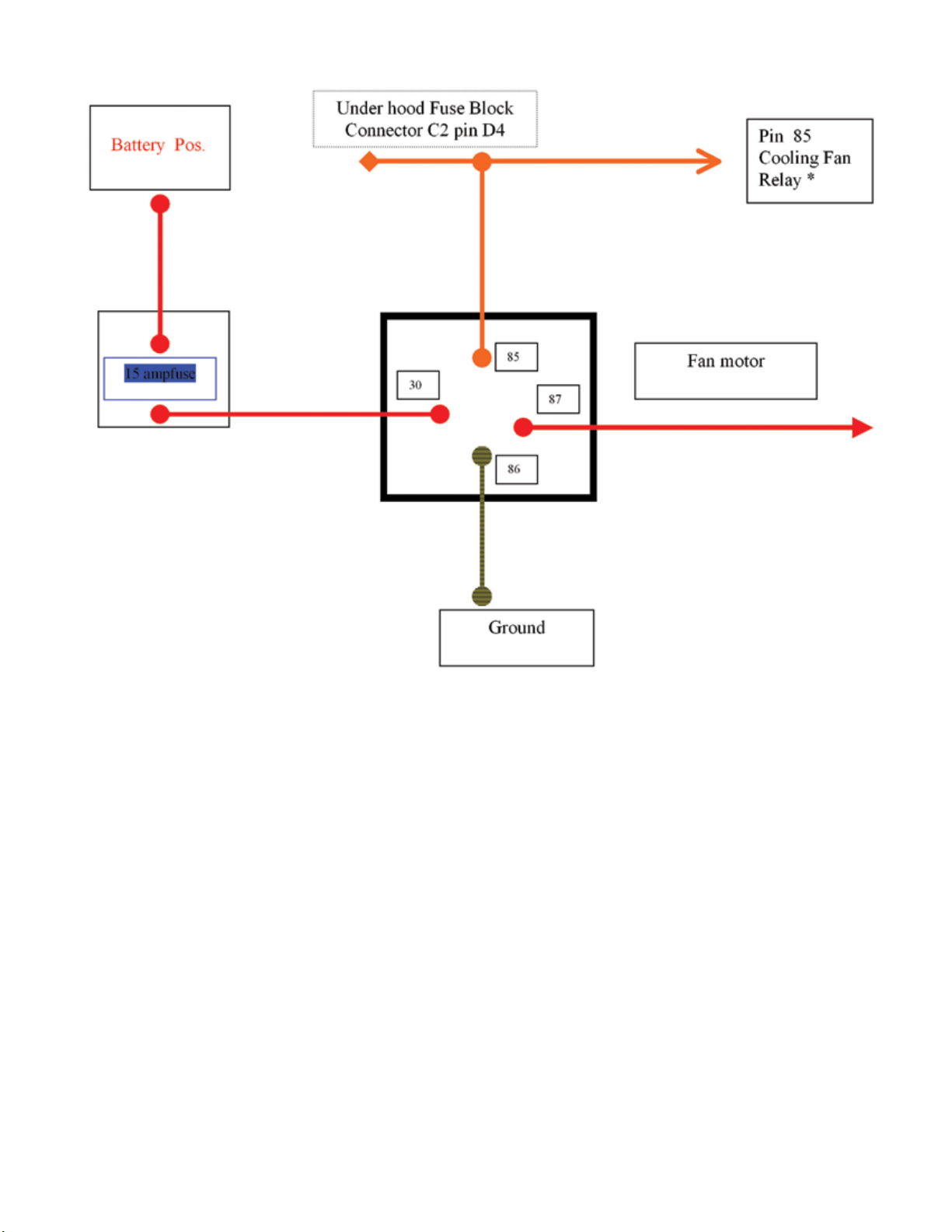
• E5 and E6 inverted Torx socket
• Cutting tool (e.g. air saw, razor knife, etc.)
• Silver Sharpie or similar paint pen
• Heat gun
• Soldering iron (optional)
• Electrical tape
• Wire stripper
• Wire crimp tool
• Wire cutter
• Pin depressor tool or small at head screw driver
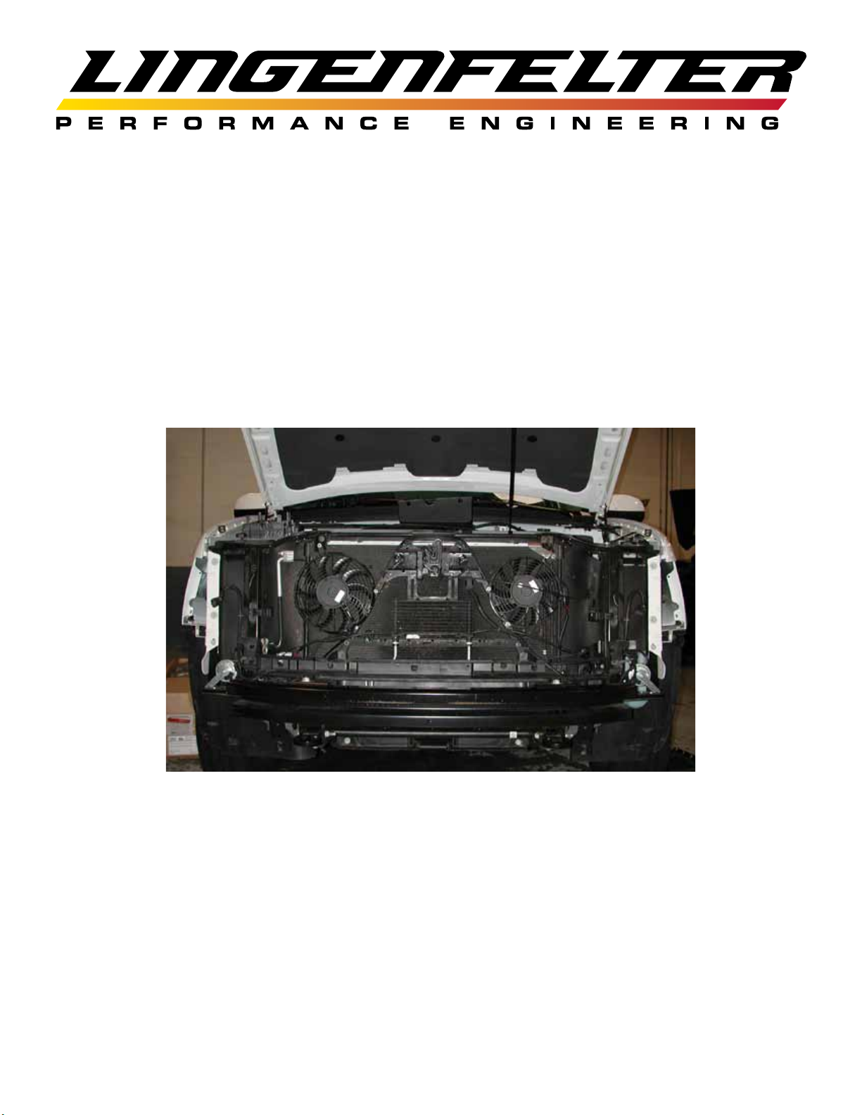
The Lingenfelter Performance Engineering (LPE) auxiliary cooling fan system is designed to improve the performance
of the air conditioning (AC) system under idling, stopped and low speed conditions on engine driven mechanical fan GM
2500 series Suburban and Yukon XL vehicles.
The system features two electric pusher fans that are packaged in front of the AC condenser to provide supplemental
airow across the AC condenser. In testing performed by LPE these fans have also shown to improve the stopped and
low speed inlet air temperature heat soak that can cause reduced initial off the line vehicle performance.
Two versions of this auxiliary cooling fan system exist:
• This version that uses the AC clutch to control the operation of the auxiliary fans (PN L300080607).
• A version that has the vehicle’s engine control module (ECM) control the fans directly. This version requires
recalibration of the factory ECM programming (PN L300090607).
The fan diameters and motor sizes have been selected for these kits to be compatible with the production GM supplied
alternators assuming that signicant other electrical accessory loads have not been added to the system. If you need
additional alternator output in order to provide for the electrical demands of these fans and other electrical components
that have been added to the vehicle, please contact LPE for information on the available higher output alternators.
If you need additional cooling fan output LPE can provide systems with higher output fans that require the use of
higher output alternators. Contact LPE with your specic requirements and we will design a system that meets your
specications.
Lingenfelter Performance Engineering also offers many other parts for these and other GM based vehicles so please feel
free to contact us regarding any other possible GM vehicle related product needs you may have.
Page
1.
Page 3
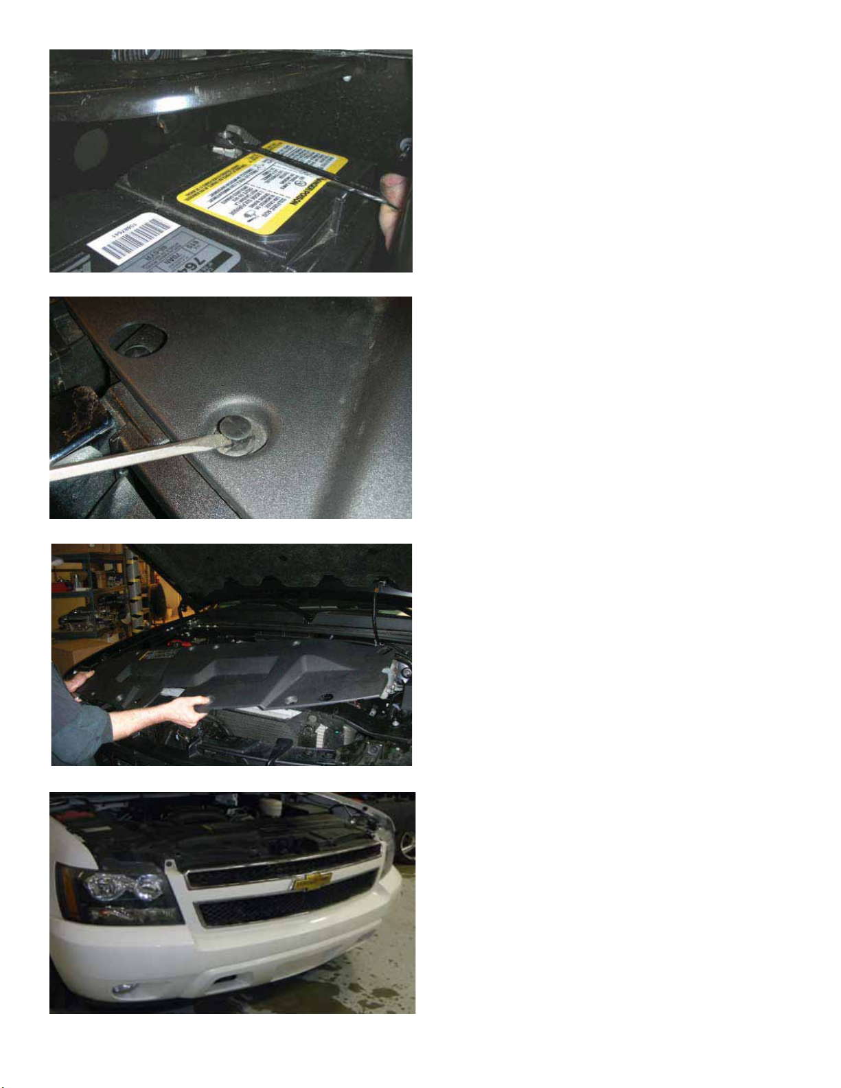
1. Using a 10 mm socket wrench, disconnect
the negative (-) battery cable from the terminal
on the battery. Cover the cable end with
electrical tape so accidental connection to the
battery does not occur.
2. Using a pry tool or at blade screwdriver,
remove and save the eight plastic pushpins
from the radiator support cover. The pushpins
will be used to re-install the cover.
3. Remove the radiator support cover from
the vehicle. Set aside to be re-installed later.
4. The front fascia and grill assembly are all
one piece. Start by removing the bolts at the top
of the grille.
Page
2.
Page 4
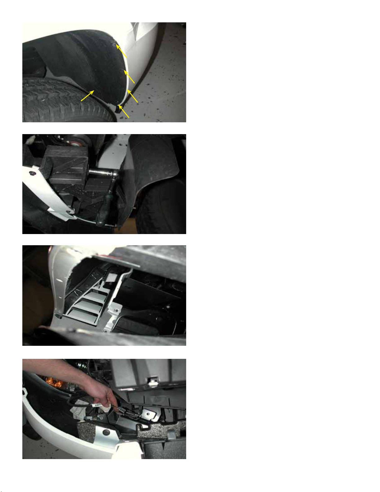
5. Next remove the two 7mm bolts and three
push clips from both of the front inner fender
wells.
6. Remove the two, one on each side,
10mm bolts securing the plastic fascia support
brackets to the metal bumper support brackets.
7. Next remove the four bolts, two on each
side, holding the fascia to the fenders.
8. With help from an assistant, carefully
pull the front fascia loose from the vehicle and
unplug the fog lights on each side. Set aside
somewhere it will not get damaged.
Page
3.
Page 5
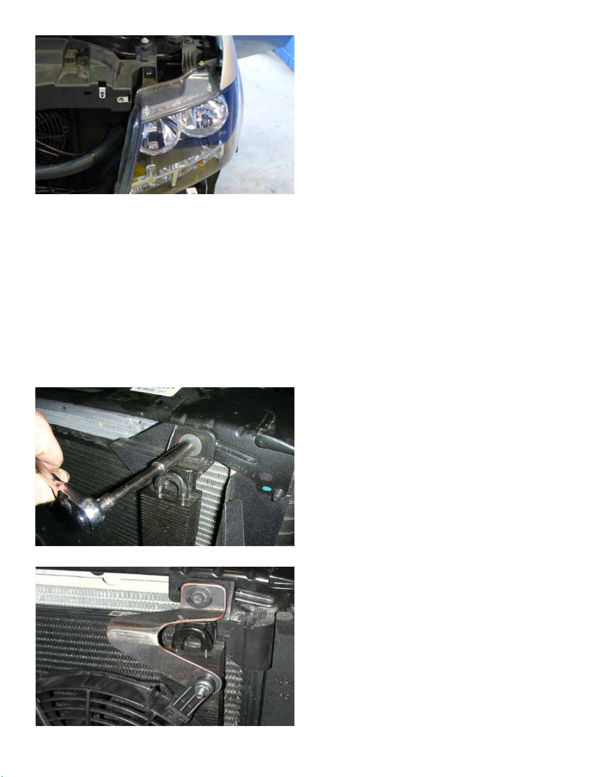
9. Remove the headlights from the vehicle,
being careful not to scratch the lens or break
the plastic brackets. Two bolts secure each
headlight assembly.
10. Remove the eight bolts on the upper
radiator support bracket and then remove the
upper radiator support bracket.
[MISSING IMAGE]
11. Locate the power steering cooler on the
driver side of the radiator assembly. Using a
10mm socket wrench, remove the bolt shown
that holds the top of the power steering cooler
in place. Save this bolt for the next step. Do not
remove the cooler.
12. Using a 10mm socket wrench, install the
driver side fan bracket (L960160607) as shown
on the driver side using the factory bolt.
Page
4.
Page 6
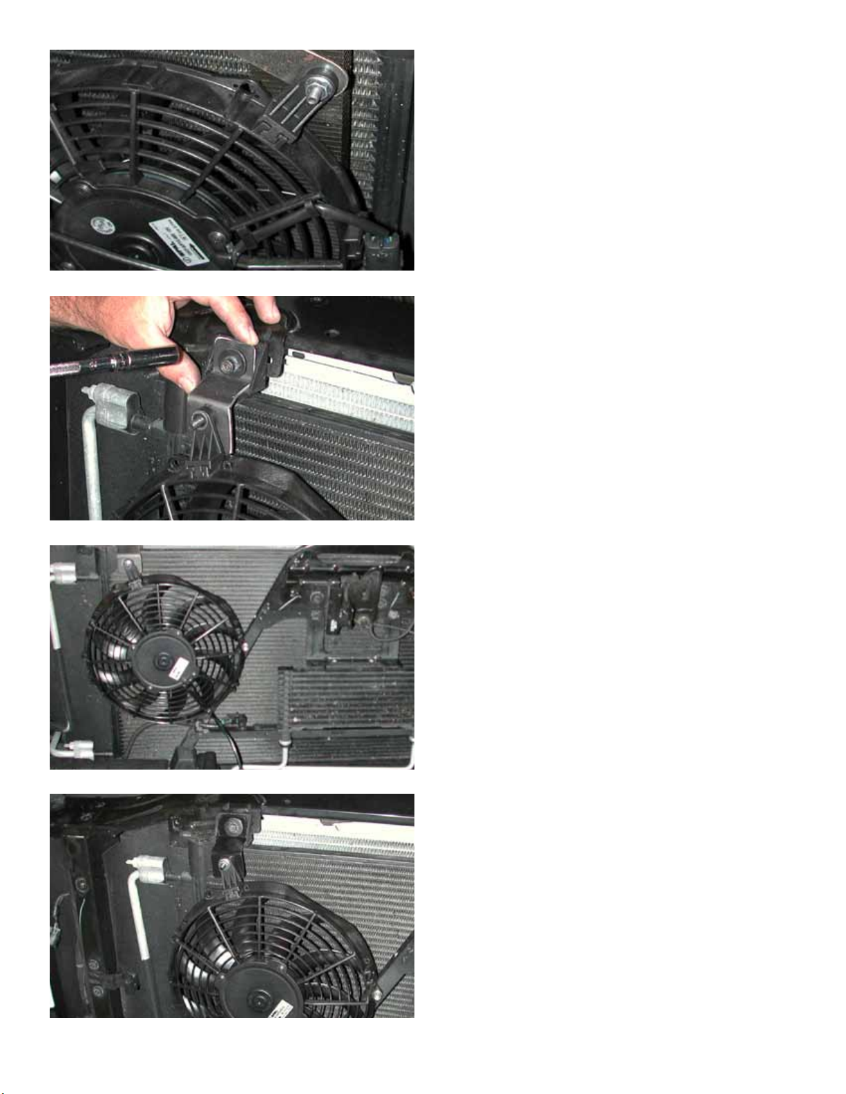
13. This auxiliary fan kit includes two different
size fans. A 225 mm (9”) diameter fan and
a 255 mm (10”) fan. The smaller of the two
fans will be mounted on the driver side of the
vehicle. Install one of the plastic fan mounting
tabs onto the 9” (225 mm) fan as shown.
Note the position of the mounting tab in relation
to the wiring harness. Using a 7/16” socket,
secure the fan to the bracket with one of the
1/4-20 Spin Lock nuts.
14. The 255 mm (10”) fan, the larger of the
two fans, will be mounted on the passenger
side of the vehicle. Using a 10mm socket,
remove the bolt that secures the passenger
side upper corner of the AC condenser. Use
the factory bolt you just removed to secure the
passenger side fan bracket (L960150607).
15. Install the remaining plastic fan mounting
tab onto the 255 mm (10”) fan.
Note the position of the mounting tab in relation
to the wiring harness. It should be roughly 180
degrees away from the harness as shown.
16. Using a 7/16” socket wrench, secure the
fan and mounting tab assembly to the bracket
using one of the supplied 1/4-20 Spin Lock
nuts.
Page
5.
Page 7
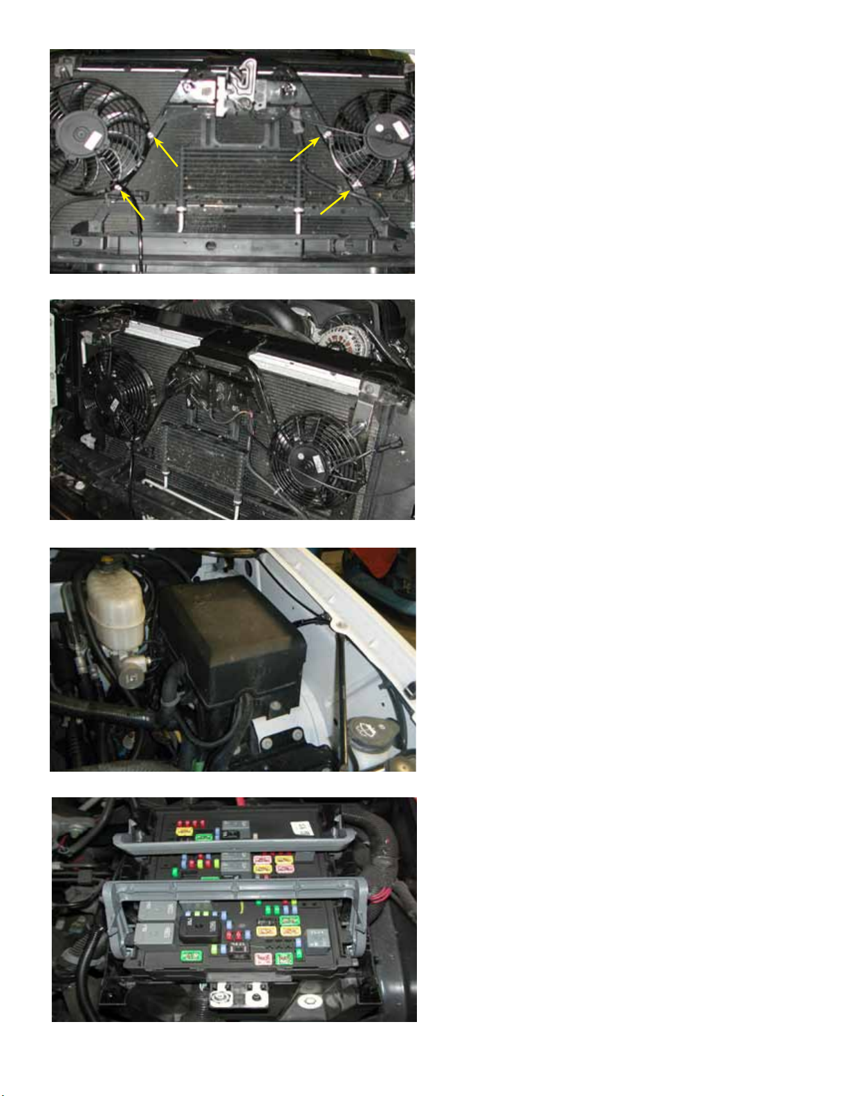
17. Mark with a center punch the location of
where the fan shroud mounting holes overlap
the factory front support structure as shown on
the left (yellow arrows).
Using a 3/16” drill bit, carefully drill four holes
(two per fan) into the “A” shaped frame. Only
drill through the front face of the frame, do not
drill all the way through the frame.
18. Secure the fans to the “A” frame using
the supplied self tapping screws (AV12351 &
AV12354). On the driver side use the longer
30mm screws along with the supplied 1/4” thick
round spacers for the smaller 9” (225mm) fan.
Install the spacers between the fan mounting
feet and the holes in the “A” frame.
The fasteners shown in the images are silver
for better visibility in the images and are not the
self tapping fasteners supplied.
19. Remove the plastic cover from the main
fuse and relay center.
20. Un-clip the gray locking tabs securing the
fuse block and remove fuse block center.
Page
6.
Page 8
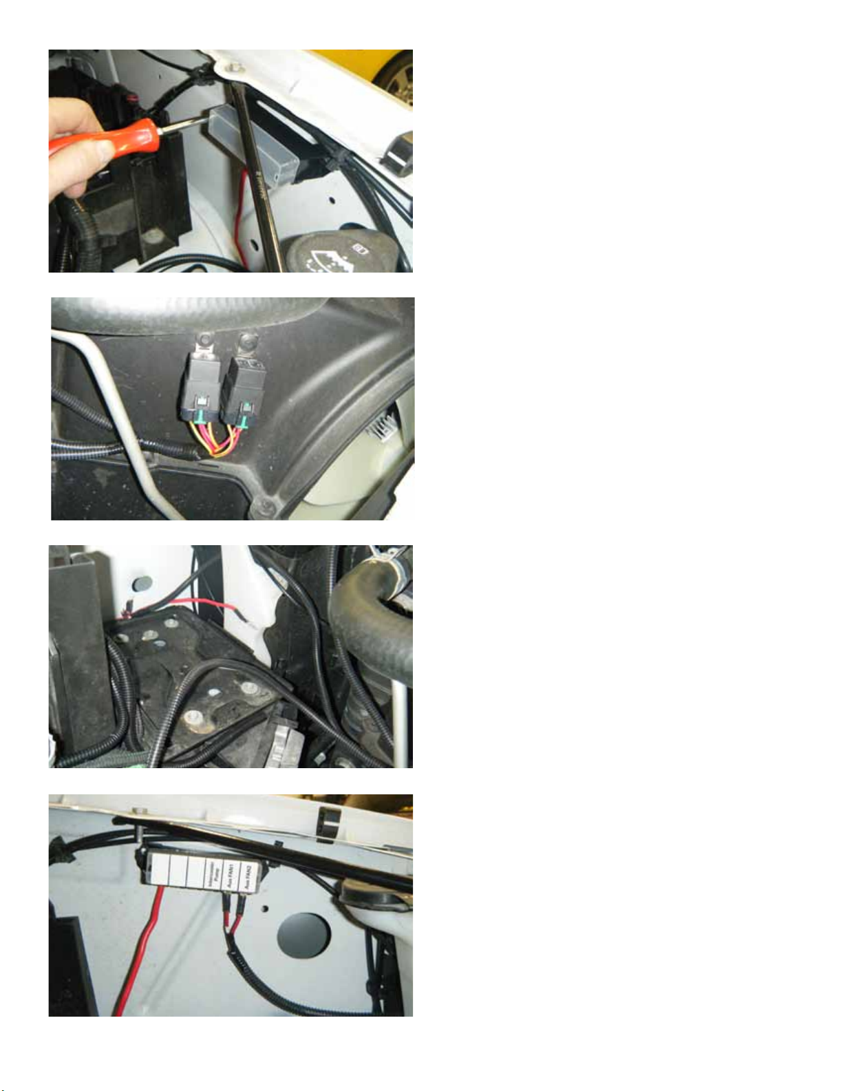
21. Mount the supplied fuse block to the
inside of the driver side front fender by drilling
two holes (1/8” drill) through the fuse block
mounting tabs. Be careful not to drill too far
or you risk damaging the outer fender. Now
using a Phillips head screw driver secure
the fuse block to the vehicle with the two
M4.2x1.41x20mm Phillips head self tapping
screws.
22. Mount the relays to the left-hand side
(driver side) of the upper fan shroud by drilling
two 1/4” holes into the plastic shroud and
securing with the supplied push-lock rivets.
23. With the relays mounted, route the red
power wires up and behind the windshield
washer bottle and over to the 6 position fuse
block.
24. Apply the fuse panel decal to the fuse
panel cover as shown. Now connect the two red
fan harness power wires to the fuse block you
installed in step 21. The red wire with the #3
on it, labeled fan #1, goes into the #2 position
on the fuse block (labeled Aux FAN1) and the
other red power wire goes to the #1 fuse block
position (labeled Aux FAN2).
NOTE - if you will be installing additional
accessories using the supplied fuse block, the
maximum fuse block capacity is 65 amps.
Page
7.
Page 9
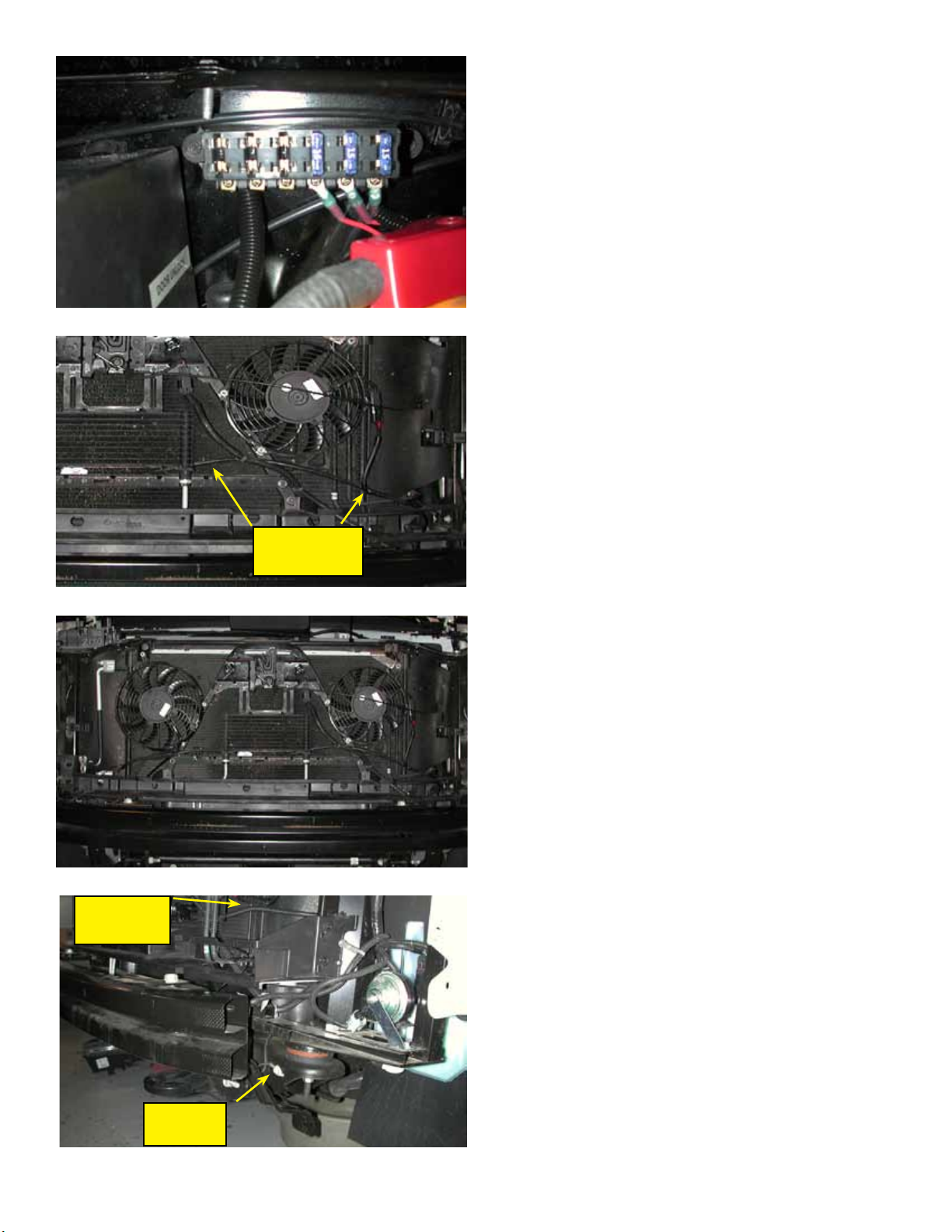
25. Install the two supplied 15 amp fuses
into the fuse block in the two far right-hand
positions.
NOTE: Ignore the third fuse and wire shown
in this image, this additional fuse is for the
intercooler uid circulation pump used in the
supercharged vehicle applications.
26. Route the fan wiring harness around the
radiator support on the driver side and along
the front of the truck. Zip tie the harness along
the way to hold it in place.
wiring
harness
wiring
harness
27. Connect the wiring harness to the fans.
Fan 1 is the driver side fan (225 mm).
Fan 2 is the passenger side fan (255 mm).
28. On the driver side, connect the ground
wire from the fan #1 side of the harness to the
frame of the vehicle on the driver side using the
existing factory ground bolt found in front of the
wheel well next to the end of the bumper beam
as shown. Secure the harness in place with Zip
ties.
ground
bolt
Page 8.
Page 10
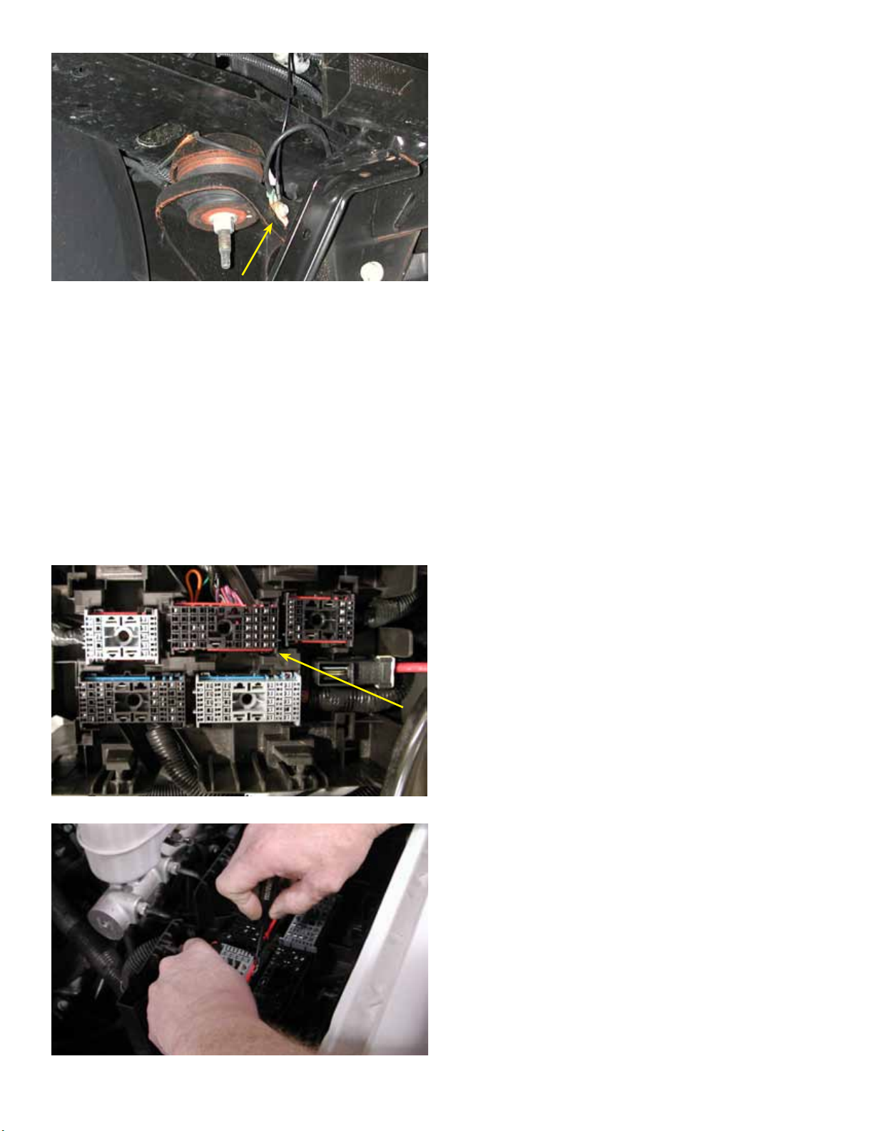
29. On the passenger side, connect the
ground wire from the fan # 2 side of the harness
to the frame of the vehicle on the passenger
side using the existing factory ground bolt found
in front of the wheel well next to the end of the
bumper beam as shown.
30. Route the portion of the fan wiring harness
that includes the yellow/black ground wire and
the orange trigger wire up past the ECM and to
the fuse block. Secure in place with some Zip ties.
[MISSING IMAGE]
31. Image of fuse block and relay center with
cover removed.
The arrow shows connector X2 (or C2) that will
be needed in the following steps. Connector
block X2 is the black connector on the left side
(passenger side), one back from the front.
32. Using a pin depressor tool or a small
screwdriver, remove connector X2 from fuse
block (see fuse block diagram for connector
numbers).
Page
9.
Page 11
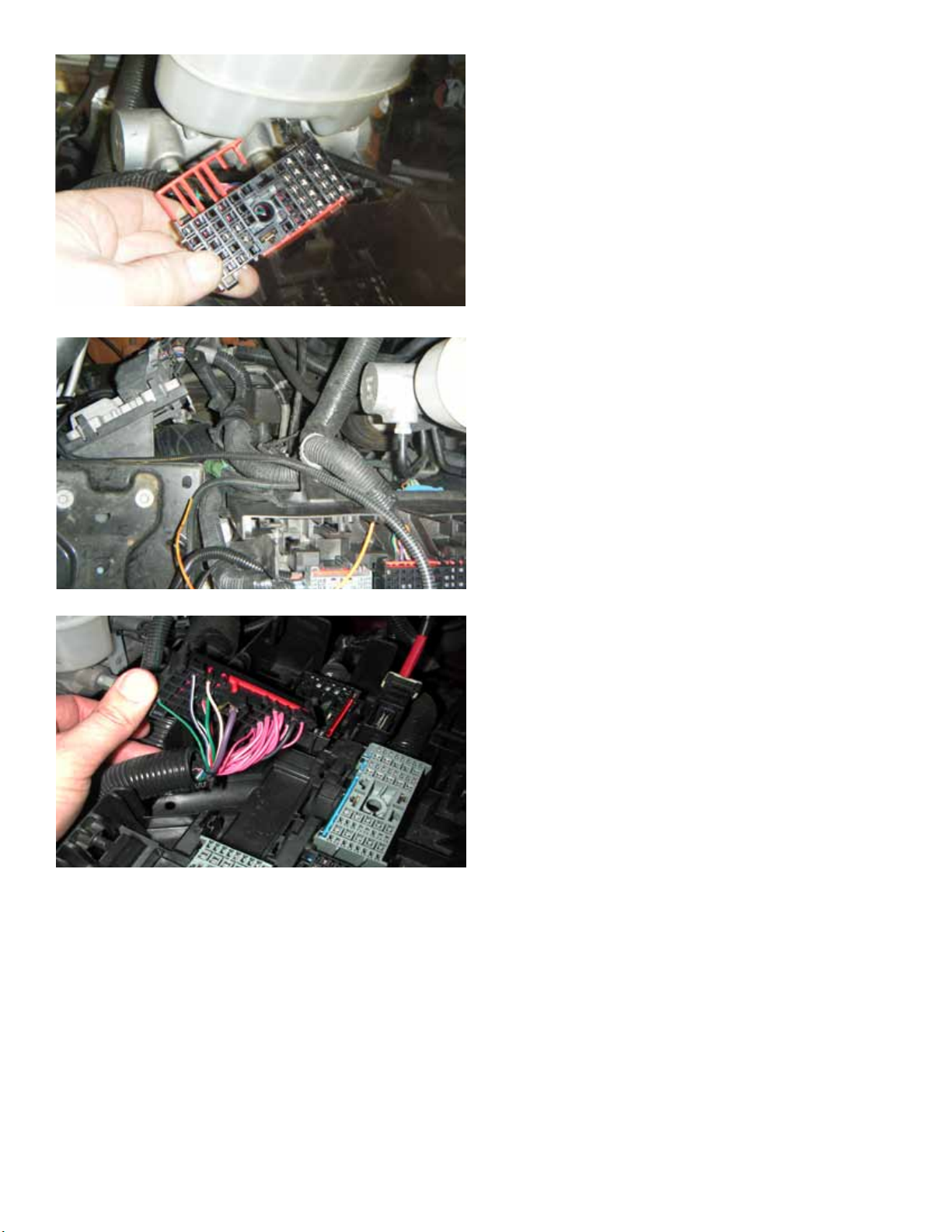
33. Remove the terminal retainers (red plastic
clips) from front end of the connector as shown.
34. Pull the orange wire from the remaining
bundle of wires in the fan relay harness. Pull the
wire out so that it exits the plastic convoluted
loom near the fuse relay center.
35. Now you will connect the orange wire
(from the fan relay harness) to the dark green
wire in connector #X2 (sometimes referred to
as C2) pin D4. This wire is the AC compressor
clutch supply voltage, circuit 59.
Refer to the connector end views on page 18.
36. Two primary ways exist to connect to
this circuit:
• Method A - cut the wire and then splice the
three wires using the supplied splice connector
(#37-40, page 11)
• Method B - remove the terminal, strip back
the insulation and solder in the spliced wire.
(#41-44, page 12)
[NO IMAGE]
Page 10.
Page 12
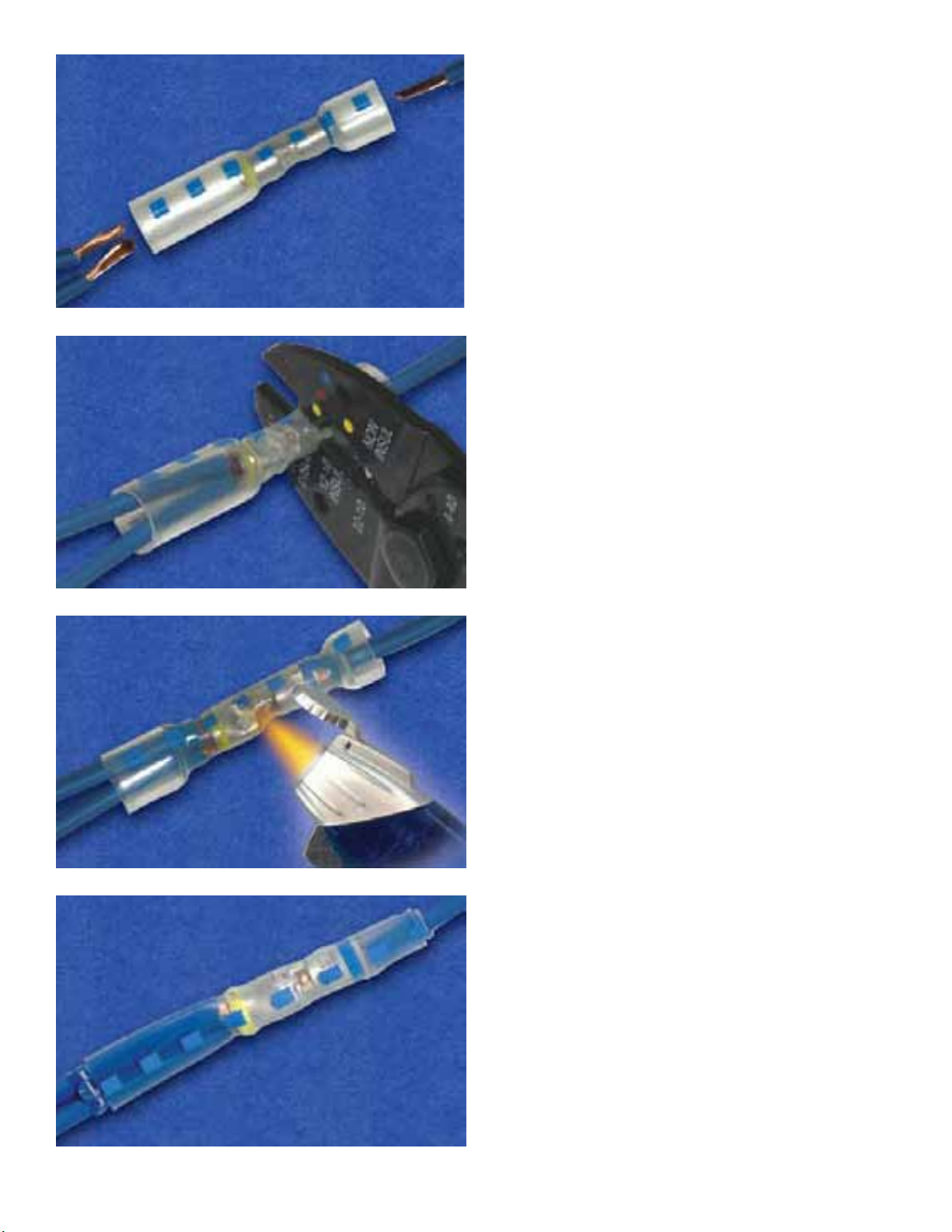
37. Method A (for method B, skip to step 41)
Cut the green wire that connects to pin D4
roughly 1-1/2” away from the terminal.
Strip back the insulation 5/8” on the harness
side of the green wire and also the orange fan
harness wire and insert the two wires into the
larger side of the supplied crimp connector (PN
DC-940010). Make sure that both wires are
properly seated and crimp the connector using
an insulated connector crimping tool.
38. On the terminal side of the green wire,
strip back the insulation 5/16”.
Insert the wire into the smaller side of the
connector, make sure the wire is properly
seated and crimp the connector using an
insulated connector crimping tool.
39. Apply heat evenly around the length of the
tubing (including the crimp area) from the center
out to the ends until the tubing fully recovers
and the adhesive ows. During the heating
process, separate the two wires in the larger
end of the connector to allow the adhesive to
ow in between the wires.
40. Remove from the heat and let cool.
Page
11.
Page 13
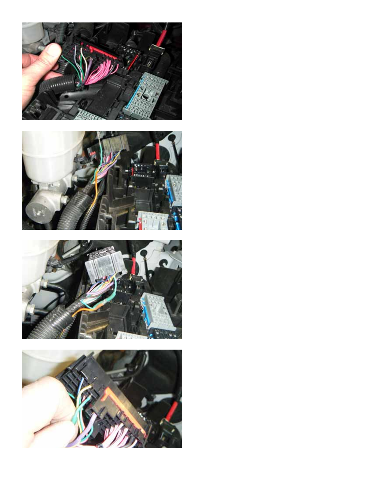
41. Method B (if using method A go to step 44)
Using a pick tool or a small screwdriver, remove
the dark green wire from connector X2, pin D4
(refer to the connector end views on page 18).
This is the AC compressor supply voltage wire,
circuit 59.
42. Roughly 1-1/2” from the terminal, strip 1/4”
section of insulation from the green wire. Cut
the orange wire to length and then strip 3/8”
of insulation from the end of the orange wire.
Splice the orange wire to the green wire by
wrapping the orange wire around the exposed
section of the green wire and then solder the
connection.
43. Slide the supplied heat shrink tube over
the terminal end of the wire. Using a heat
gun, shrink the tubing over the soldered splice
connection.
44. Re-install the terminal into the connector
X3, cavity D4.
Page
12.
Page 14
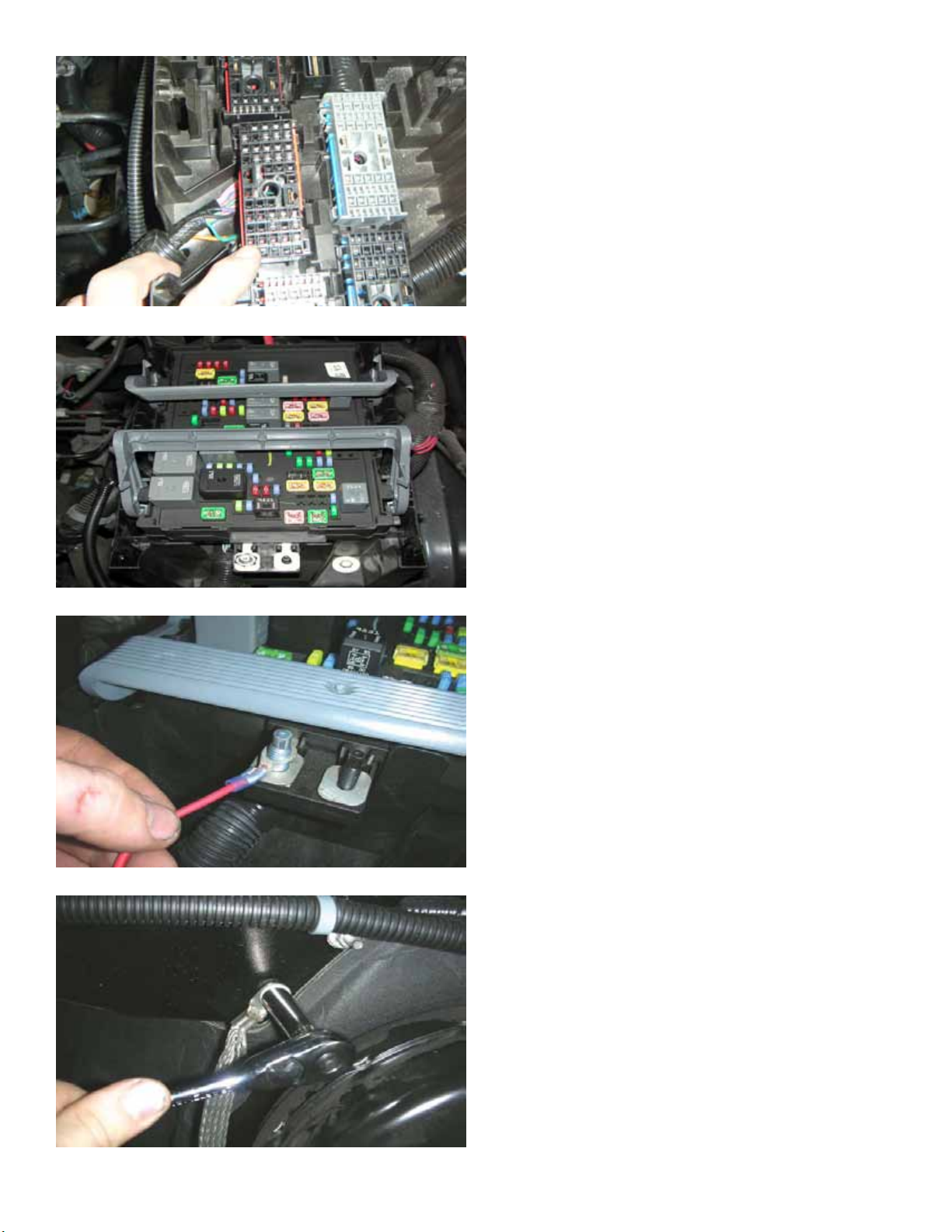
45. Re-install terminal retainer clip on the X2
connector and install it into the fuse black and
relay center base.
46. Re-install the fuse block onto the fuse
block base.
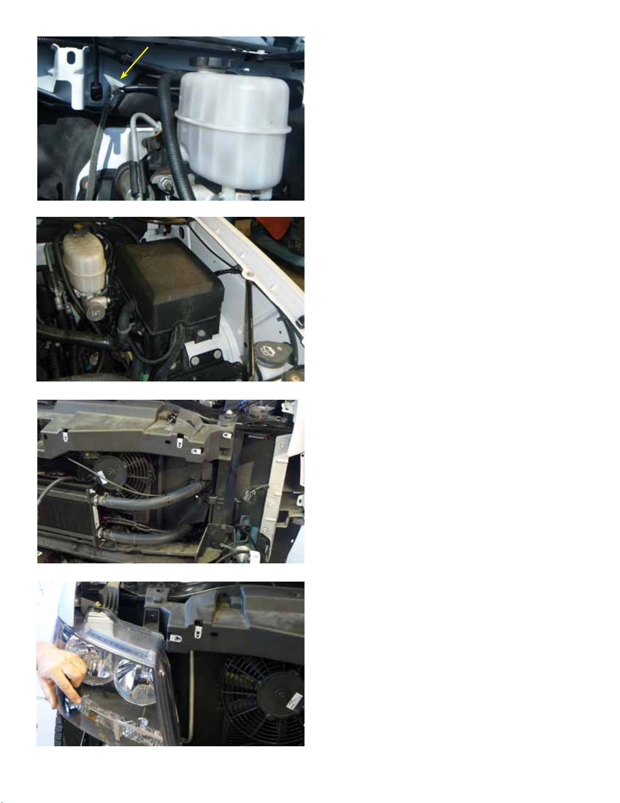
47. Attach the main power wire from the
supplied 6 position fuse block to the stud in the
factory fuse box using the M8 nut. Tighten using
a 13 mm socket.
Install the supplied 22” long section of 1/4” high
temperature loom to the red wire between the
supplied fuse block and the mounting stud.
Since not all vehicles come equipped with a M8
nut on the stud from the factory, a M8 nut has
been provided in case one is not already there.
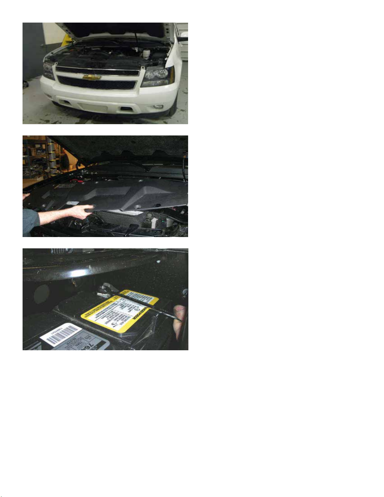
48. With a 10mm socket wrench, remove the
nut securing the ground cable to the rewall.
Page
13.
Page 15
49. Route the ring terminal equipped yellow/
black ground wire from the fan wiring harness
back alongside the fuse block to the rewall and
across the brake booster to the ground stud.
Install the ring terminal onto the ground stud
and then secure it in place with the factory nut.
50. Re-install the fuse and relay panel cover.
51. Re-install the upper radiator cover.
Ignore the intercooler heat exchanger shown
in this image. The heat exchanger is from the
supercharged vehicle applications but the fan
kit is the same fan kit.
52. Re-install the headlights.
Page
14.
Page 16
53. Reinstall the front fascia on the vehicle
using the stock hardware.
54. Reinstall the radiator support cover on the
vehicle using the stock hardware.
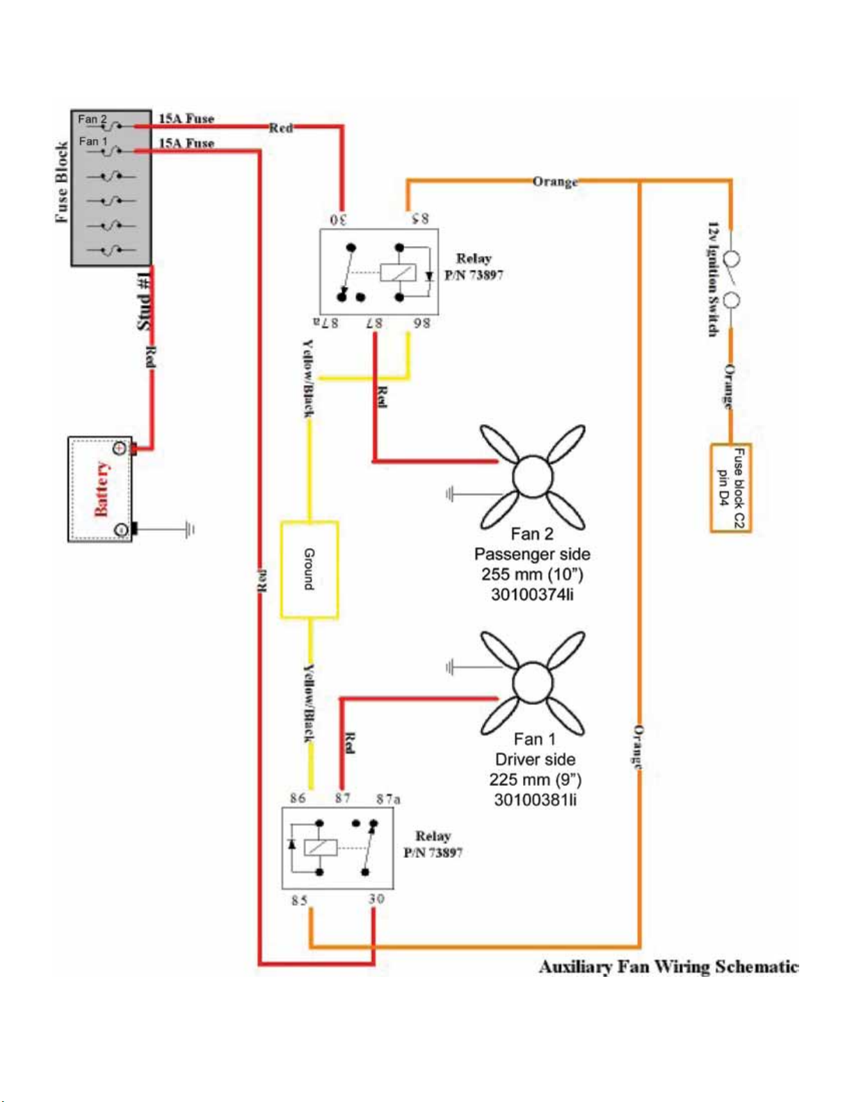
55. Re-connect the battery cable with a 10mm
socket wrench.
56. You have completed the installation. The
auxiliary fans should now be in operation when
ever the AC system is being operated.
Page
15.
Page 17
2007-2010 2500 Suburban & Yukon XL aux fan harness, AC control, PN L480110607
Page
16.
Page 18
Page 17.
Page 19
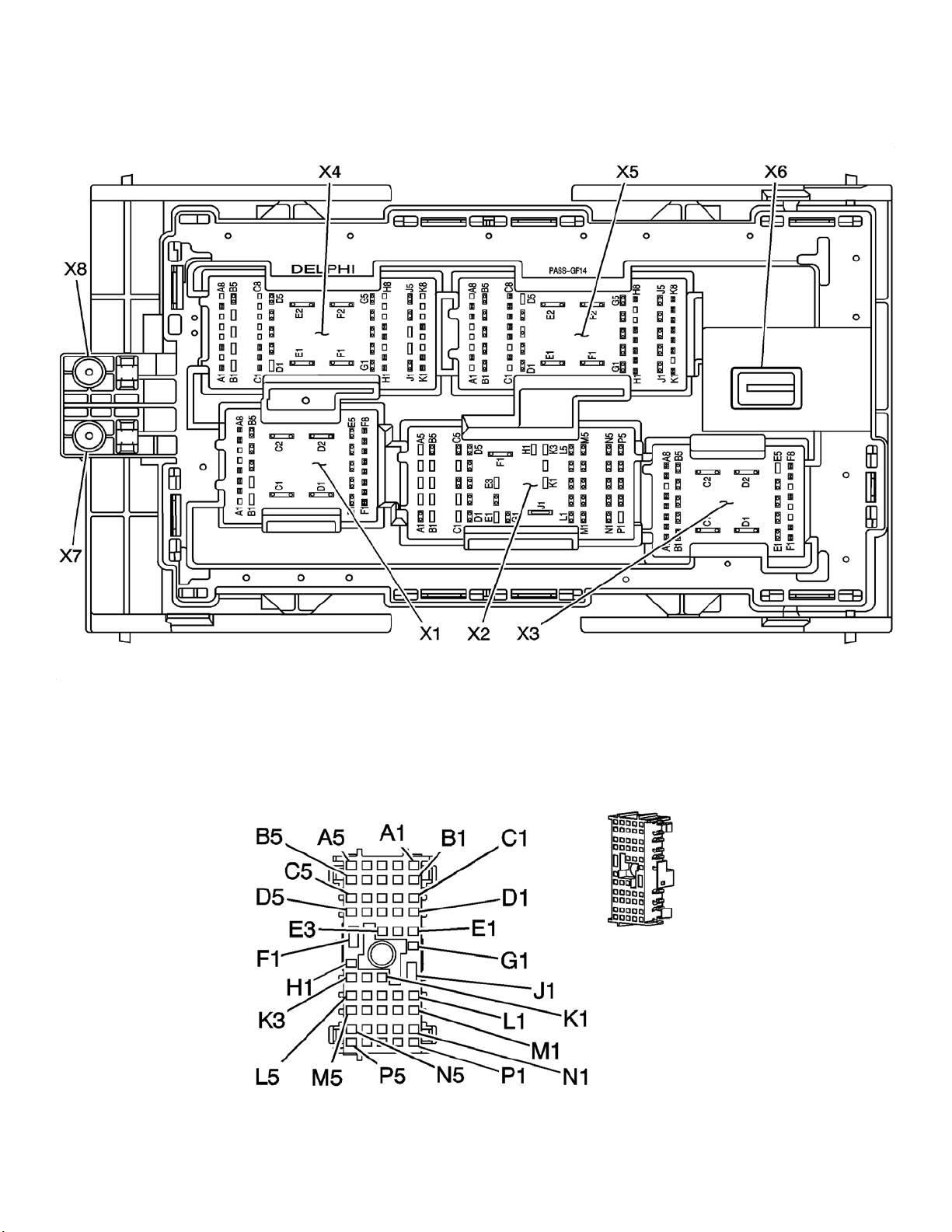
Relay and fuse panel connector underview layout (NOTE - this is the underside of the fuse and relay
connector so it is a mirror image of the mating connector panel in the vehicle once you have removed
this panel from the vehicle):
Connector X2:
Page
18.
Page 20

Parts List
Quantity DESCRIPTION Part #
1 Passenger side fan bracket, CK truck fan system L960150607
1 Driver side fan bracket, CK truck fan system L960160607
1 2007-2010 2500 Suburban & Yukon XL aux fan harness, AC control L480110607
1 Spal 225 mm fan with WeatherPak connector 30100381li
1 Spal 255 mm fan with WeatherPak connector 30100374li
2 Fan mounting tab 30130032
1 6 gang fuse panel, 65 amp capacity 73897
2 3/8" high temperature loom, 22 inches 1764
2 15 amp buss fuse (blue) 782-2184
1 6 gang fuse panel decal, white L920050000
2 M4.2x1.41x20mm Phillips washer head self tapping screw 12060
2 Aluminum round spacer 5/8" OD, 1/4" Length, 1/4" Screw Size 92511A087
2 M6.3-1.81 x 20mm self tapping screw AV12351
2 M6.3-1.81 x 30mm self tapping screw AV12354
2 1/4-20 Spin Lock nut 34292
1 M8X1.25 ange nut 90701
6 Zip tie, 7.5", black
1 16-14 AWG heat shrink tube
1 In-line crimp connector, sealed, 16-14 awg (clear w blue) DC-940010
2 Push fastener AV12567
1 Installation instructions
1 Lingenfelter decal L920010000
Lingenfelter Performance Engineering
1557 Winchester Road
Decatur, IN 46733
(260) 724-2552
(260) 724-0422 fax
www.lingenfelter.com
L300080607 LPE Auxiliary Fan Kit With AC Clutch Control Installation Manual - Rev E.indd
Page
19.
 Loading...