

Page 1
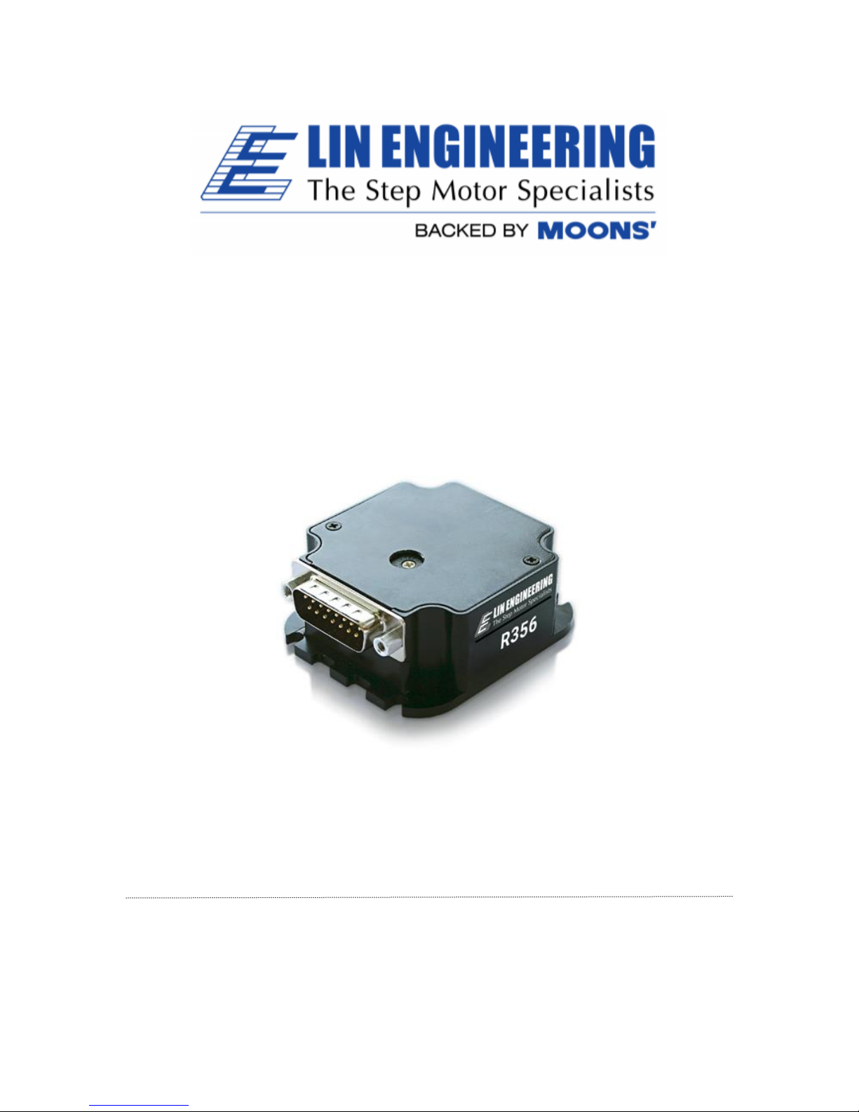
R356 Driver/Controller
Built-in 256x Microstepping Driver
and encoder feedback for position correction
User Manual
Version 1.10
Lin Engineering
16245 Vineyard Blvd., Morgan Hill, CA 95037
Page 2
R356 Controller & Driver Page 2 Version 1.10
Lin Engineering 3/16/2018
Thank you for purchasing the R356 Controller with Microstepping Driver. This
product is warranted to be free of manufacturing defects for one year from the date
of purchase.
PLEASE READ BEFORE USING
Before you begin, ensure there is a suitable DC Power Supply. Do not connect or
disconnect the DB-15 cable while power is still being applied to the
controller. This will damage the board. The minimum voltage for the controller is
12.0 volts.
Under any circumstances, do not exceed +40 VDC.
DISCLAIMER
The information provided in this document is believed to be reliable. However, no
responsibility is assumed for any possible inaccuracies or omissions. Specifications
are subject to change without notice.
Lin Engineering reserves the right to make changes without further notice to any
products herein to improve reliability, function, or design. Lin Engineering does not
assume any liability arising out of the application or use of any product or circuit
described herein; neither does it convey any license under its patent rights, nor the
rights of others.
This manual revision, is provided for distribution with R356 controllers sold through
Lin Engineering
Special Symbols
Indicates a WARNING and that this information could prevent
injury, loss of property, or even death (in extreme cases).
Page 3
R356 Controller & Driver Page 3 Version 1.10
Lin Engineering 3/16/2018
R356 User Manual
Product: R356
Version: 1.10
Date: 3/16/2018
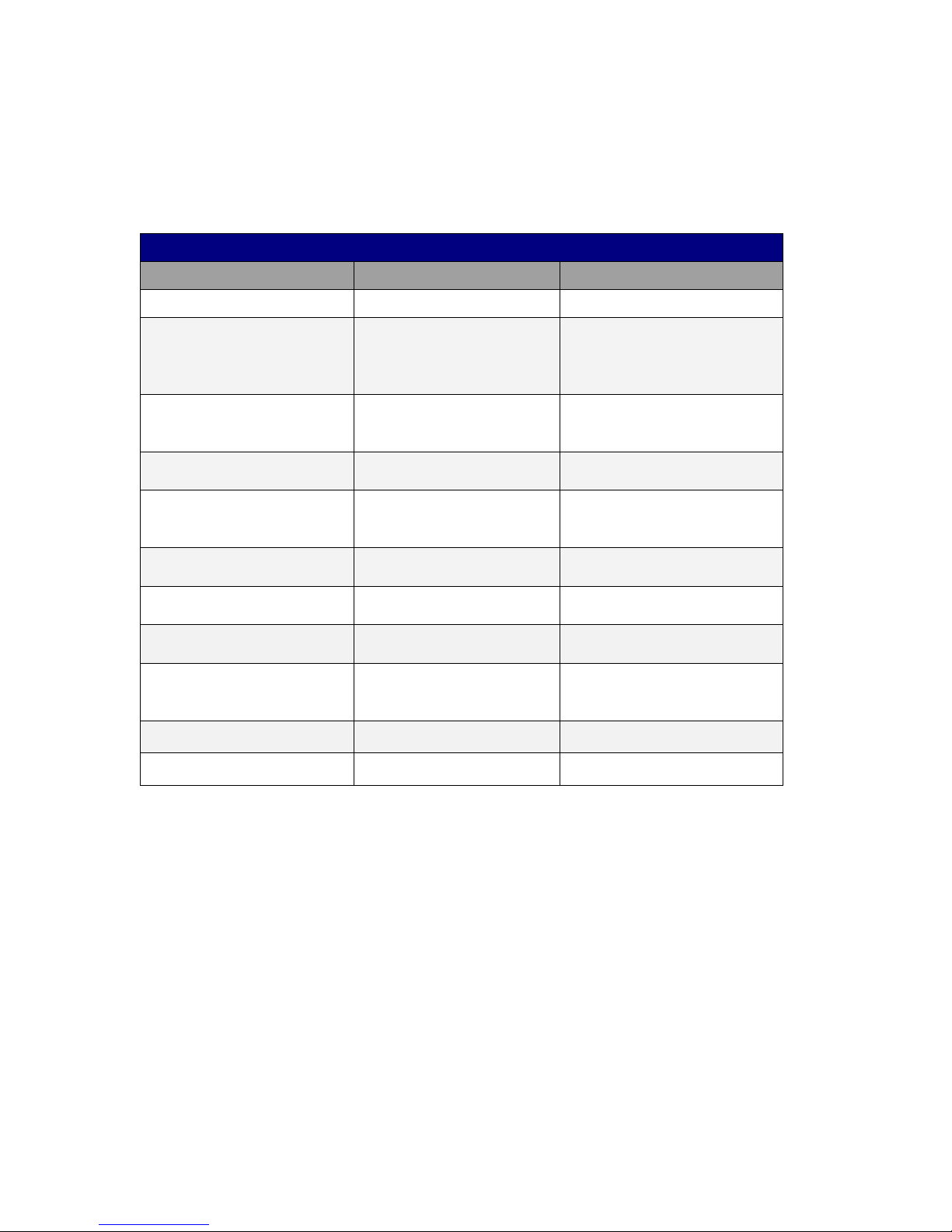
Version History
Version
Date
Description of Changes
1.00
7/01/2008
New User Manual
1.01
4/3/2009
Added new RS485-232
converter card info and
color code for opto sensor
connection page 18.
1.02
8/11/09
Added max surface
temperature. Updated
encoder cable image.
1.03
9/16/09
Updated image for LED
connection.
1.04
9/18/09
Updated pinouts and
Appendix for step/dir
mode.
1.05
10/29/2009
Added full step as a
resolution option.
1.06
2/17/2010
Updated typo on page 6
for max step pulse rate.
1.07
11/03/2010
Updated step frequency
to 16.7MHz
1.08
8/19/2014
Driver outputs updated
Replaced Hyper Terminal
with LinCommand
1.09
5/16/2016
Updated links and specs
1.10
3/16/2018
Update Name and Logo
Page 4
R356 Controller & Driver Page 4 Version 1.10
Lin Engineering 3/16/2018
Table of Contents
1. FEATURES
Designer’s Kit with USB communication…………………………….……….. 5
Designer’s Kit with RS232 communication…………….…………….……….. 5
R356’s Encoder Option…………….…………………………………………. 5
Default Settings…………….……………………………………………….…. 6
2. ELECTRICAL SPECIFICATIONS
Digital I/O Specifications…………….…………………………………….…. 6
3. OPERATING SPECIFICATIONS
Communication Specifications………………..…………….………………... 6
4. MECHANICAL SPECIFICATIONS
Dimensions…………….……………………..……….………………………. 7
5. PIN ASSIGNMENTS
BD-15Pin Assignments …………….……………………..……………..…… 8
Connecting to the USB485 Card …………….………………………….……. 9
Connecting to the RoHS RS232-485 Card …..………………………….……. 9
6. CONNECTION SPECIFICATIONS
Quick Start USB-485 Converter Card …………….………………………..... 10
Quick Start RS232-485Converter Card …….…….………………………….. 11
Mating Connectors …………….……………………………………………... 12
7. CONFIGURING AND CONTROLLING THE R356
LinCommand Setup …………….…………………….……………………...... 13
Setting the Current…………….…………………………………………….... 14
Connecting Multiple R356 Units ……………………………………………... 15
Changing the Address of the Controller….………….………………………... 16
Connecting Accessories…………….…………………………………………. 16
Push Button…………….…………………………………………………….. 16
LED or other output ………………………………………………………….. 17
Optical Sensors …………….……………………………………………..….. 17
8. APPENDIXES
Appendix A Encoder Usage ……………………………………………….... 18
Appendix B Amps/Phase VS Amps Peak ……………………………………. 19
Appendix C Step and Direction Mode………………..……………………… 22
Appendix D Motor Connections ……….……………………………..……… 21
Appendix E Troubleshooting ………………………..………………………. 23
Page 5
R356 Controller & Driver Page 5 Version 1.10
Lin Engineering 3/16/2018
1. FEATURES
Operates from +12VDC to +40VDC
Single 2 wire bus linking up to 16 R356 controllers (on RS485 bus)
3.0 Amp Peak Chopper (PWM) Driver (2.14 A/Ph)
Full step, 1/2, 1/4, 1/8, 1/16, 1/32, 1/64, 1/128, 1/256 step resolution
Stand alone operation with no connection to a PC
Execution Halt pending switch push button
Pre-wired internally for Opto Switch inputs
Homes to an Opto or Switch closure with a single command
Fully programmable ramps and speeds
Four digital I/O and two fixed output channels
Switch selectable address
Software selectable "Move" and "Hold" currents
Two inputs can be used for left and right limit switches
Option to use unit as a driver only and accept TTL step pulses
Takes in single-ended optical encoder input for position correction
Hold Current automatically selected upon move completion
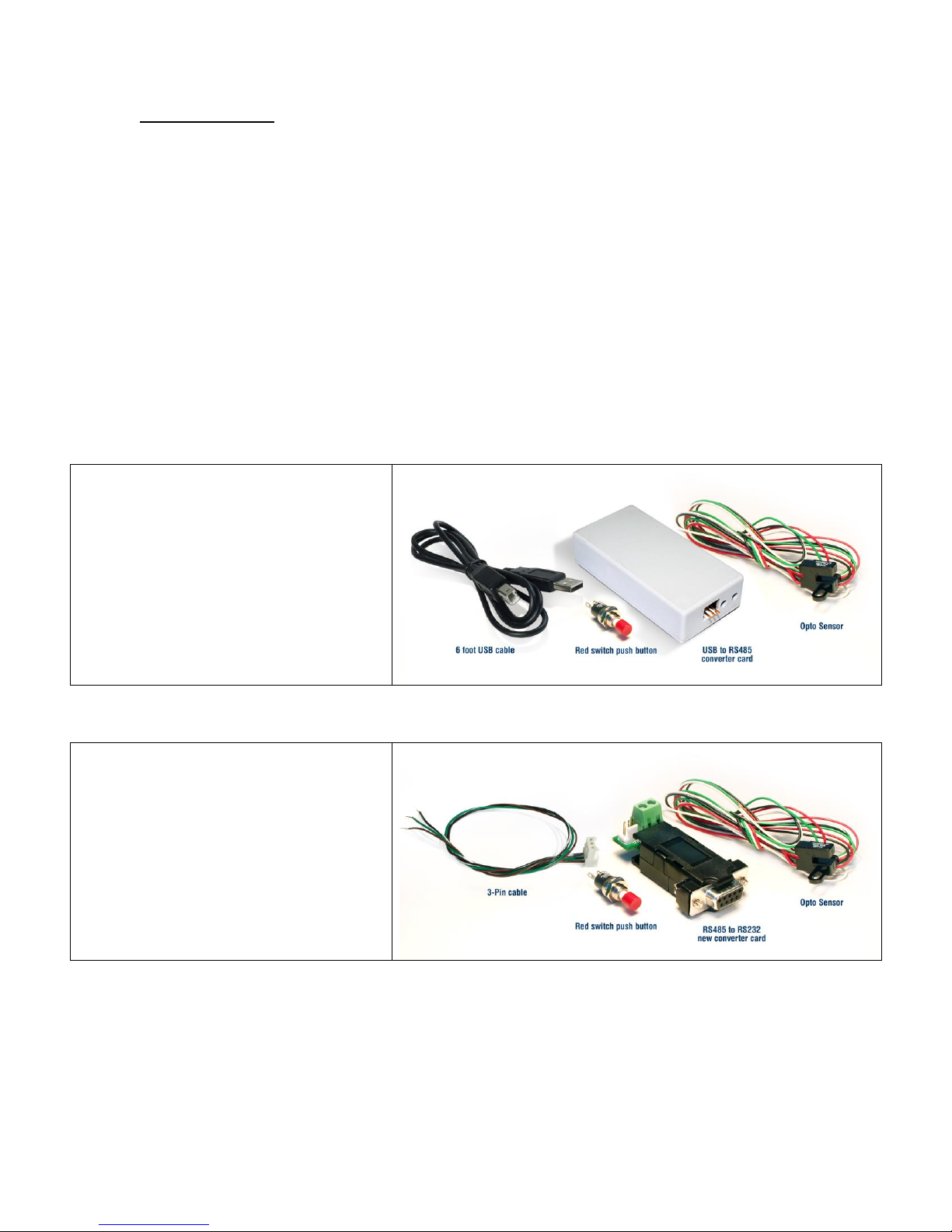
Designer’s Kit with USB communication
Here is the list of components if you
have purchased the optional
Designer’s Kit:
USB to RS485 converter card
A switch push button
Opto Sensor
A USB 6 foot long cable
3-Pin cable (optional usage)
Lin part number: USBKIT
Designer’s Kit with RS232 communication
Here is the list of components if you
have purchased the optional
Designer’s Kit:
RS485 to RS232 converter card
A switch push button
Opto Sensor
3-Pin cable (optional usage)
Lin part number: RS232KIT
R356’s Encoder Option
A single-ended optical encoder must be installed on your motor in order to have
encoder feedback. Position correction mode can be turned on such that it will
continually send step pulses until the true desired position and actual position equals
each other. The option of simply sending an error report is also possible. The R356
must first be set up to work with the encoder by understanding the CPR and
calculating an encoder ratio. See the Appendix B of this user manual.
Page 6
R356 Controller & Driver Page 6 Version 1.10
Lin Engineering 3/16/2018
Default Settings
Function (command)
Description
Running Current (m)
25% of 3.0 Amps (0.75 Amps)
Holding Current (h)
10% of the running current
Step Resolution (j)
256x
Top Velocity (V)
305175 pps (microsteps/sec)
Acceleration (L)
L=1000, 6103500 μsteps/sec
2
Position
0
Microstep smoothness (o)
1500
Outputs (J)
Both are turned off, J0, Outputs 1 & 2
Baud Rate
9600 bps
Table 1: Default Settings
2. ELECTRICAL SPECIFICATIONS
Supply Voltage: +12 to +40 VDC, 3 Amps
Peak Current: 0.3 to 3.0 Amps
Digital I/O Specifications
Number of I/O 4
Number of Outputs 2
Input Voltage +0 VDC to +5 VDC (0 to 24V tolerant, but 5V recommended)
Input Current 700 mA
Pull-up Resistors 20k Ω
Protection Static Protection to the microprocessor
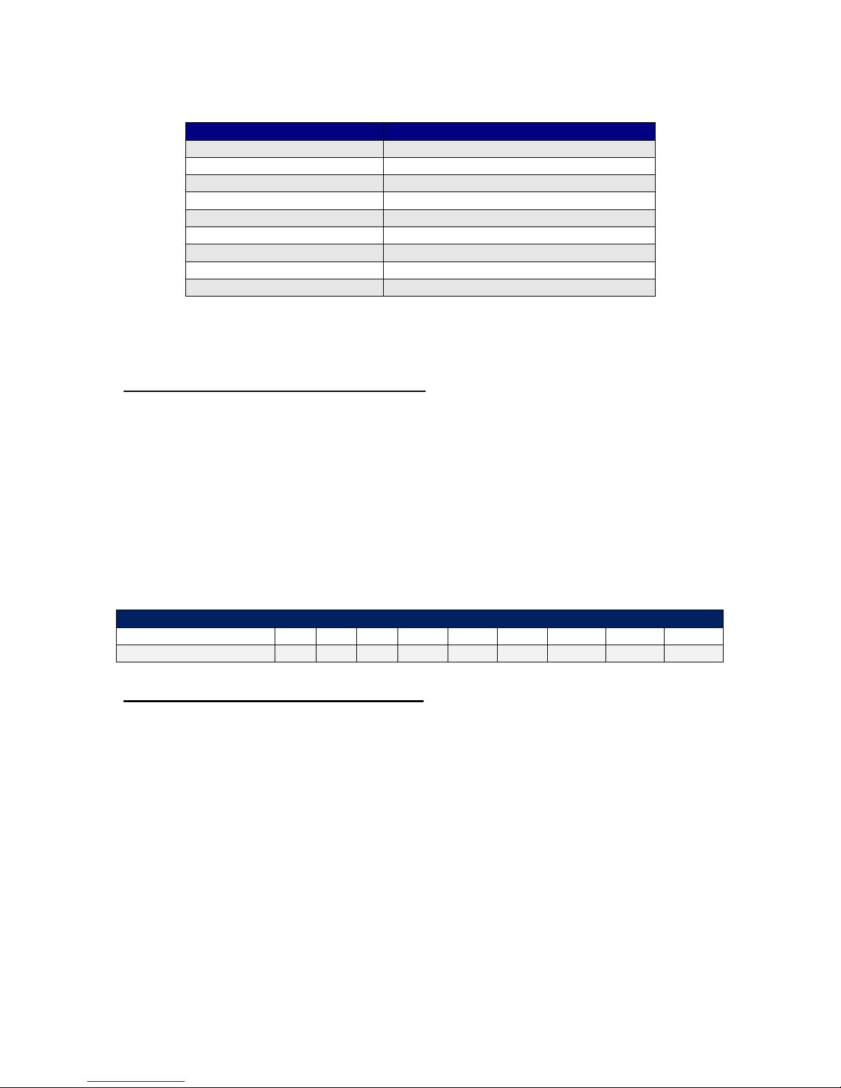
For a 1.8° stepper:
Steps per Revolution
200
400
800
1600
3200
6400
12800
25600
51200
Micro step size
1 2 4 8 16
32
64
128
256
3. OPERATING SPECIFICATIONS
Maximum Step Frequency 2^24 (pps) or 16.7MHz
Operating Temperature Range 0° to 50° C
Storage Temperature Range -20° to 70° C
Maximum surface temperature 70°C
Communication Specifications
Interface Type RS485 (RS232 or USB with a converter card)
Baud Rate 9600*, 19200, or 38400 bps
# Bits per character 8 Data
Parity None
Stop Bit 1
Flow Control None
*default/recommended
Page 7
R356 Controller & Driver Page 7 Version 1.10
Lin Engineering 3/16/2018
4. MECHANICAL SPECIFICATIONS
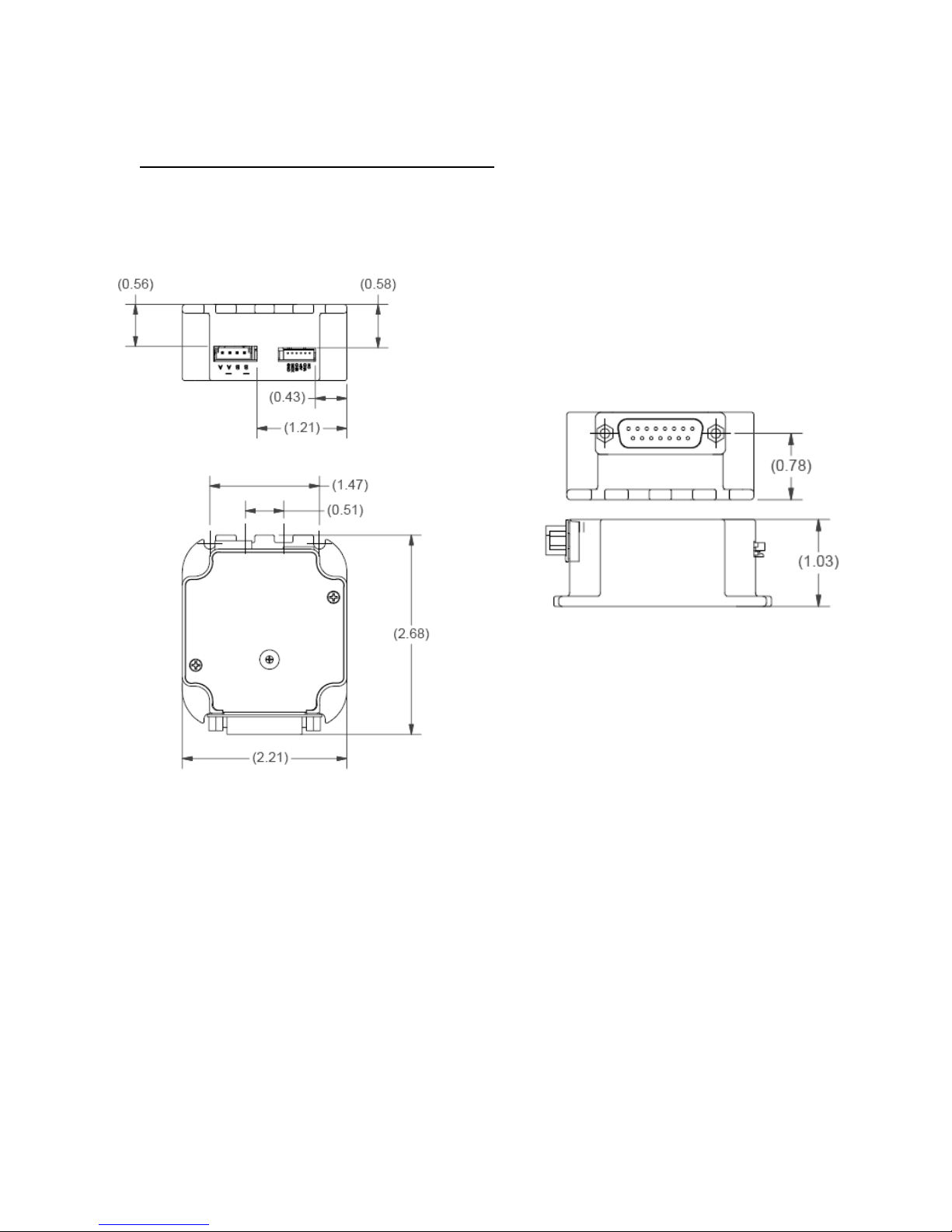
Dimensions
Figure 1: Dimensions
Page 8
R356 Controller & Driver Page 8 Version 1.10
Lin Engineering 3/16/2018
5. PIN ASSIGNMENTS
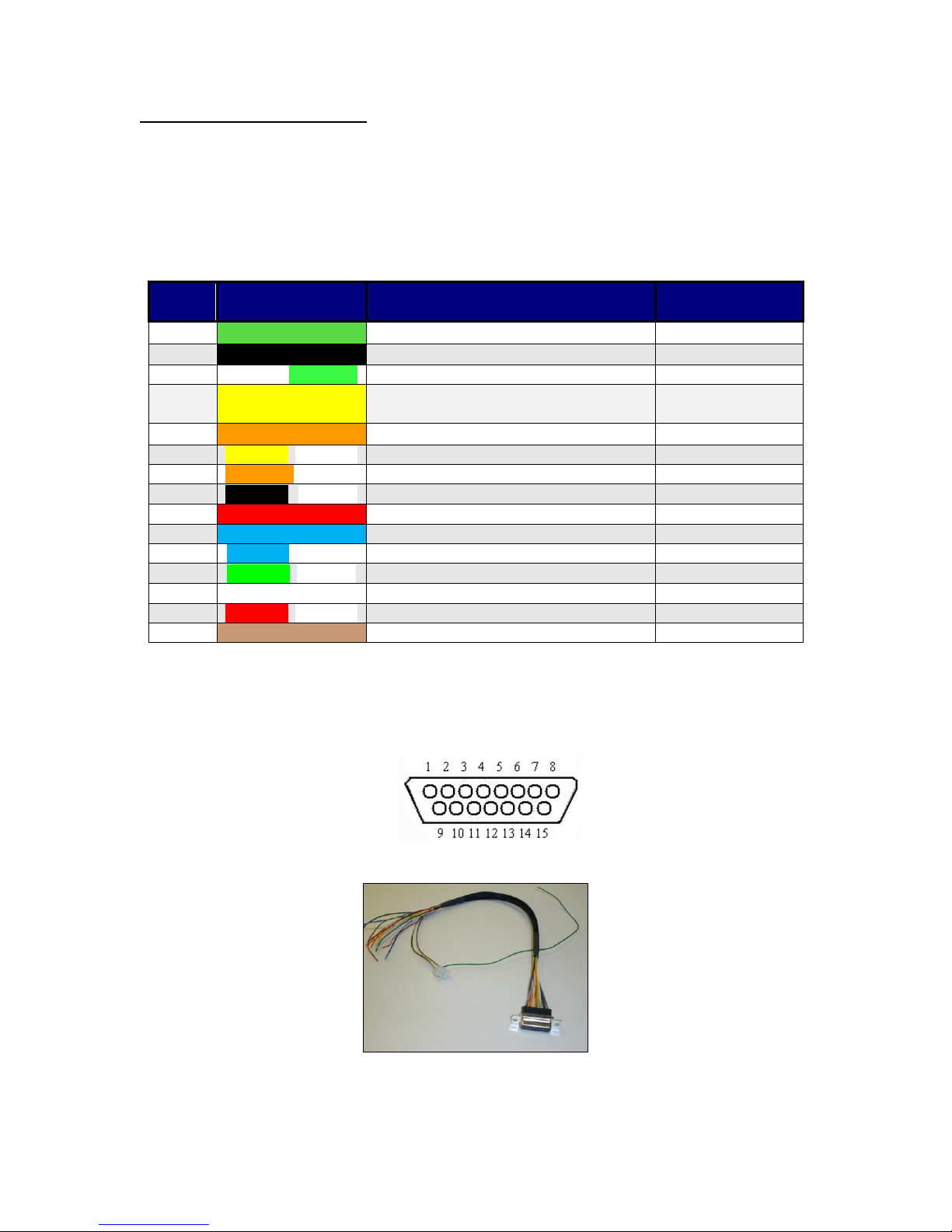
A DB-15 female connector cable comes with every R356 unit. It receives power and
provides the control connections for the R356 Unit. On the opposite end of the DB15 female connector cable, there is a 3 pin connector provided for the converter card
in order for the R356 to communicate with the PC. The four I/O wires are colored
Orange, Orange/White, White and Red/White. This will allow for options such as
solenoids, relays, opto isolators, LED’s and many other input and output connections.
PIN #
COLOR
FUNCTION
I/O # or
Function
1
Green
Power Ground
2
Black
1A On/Off Output
Driver 2
3
White / Green
Direction Input (see Appendix D)
4
Yellow
+5VDC Input for Opto Isolated
STEP and DIR (see Appendix D)
5
Orange
Input 2
Input 2 / Jog2
6
Yellow / White
Internal Power for Opto Sensor
7
Orange / White
Input 3 (Opto Input)
Input 3 / Opto1
8
Black / White
RS485 A
9 Red
+12V TO +40V POWER
10
Blue
1A ON/OFF Output
Driver 1
11
Blue / White
Step Input (see Appendix D)
12
Green / White
Signal Ground
13
White
Input 1
Input 1 / Jog1
14
Red / White
Input 4
Input 4 / Opto2
15
Brown
RS485 B
Table 2: Pin assignments
*Inputs are labeled 1, 2, 3 and 4 for programming the ‘Halt’, ‘Skip’, and special
mode ‘n’ commands.
Figure 2: DB-15 Female Cable Connector (Rear View of R356 unit)
Cable 090-00096 (connects with either RS485-232 or USB485 Card)
Page 9
R356 Controller & Driver Page 9 Version 1.10
Lin Engineering 3/16/2018
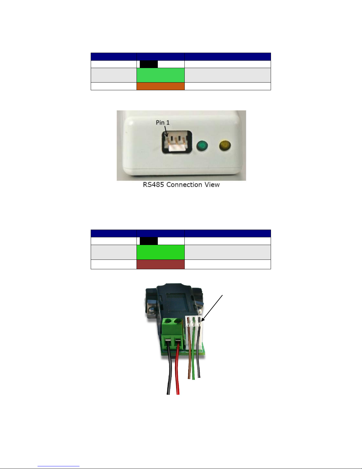
Connecting to the USB485 card
R356 pin#
R356 color
*USB485 pin#
8
Black/White
1 (RS485A)
1
Green
2 (GND connect to Power
Supply Ground)
15
Brown
3 (RS485B)
Table 3: Pinouts for using USB485
*Pin #1 is located here:
Figure 3: USB to RS485 converter card, p/n USB485
The USB485 converter card does not require power (it receives power from the PC). Power is still needed
for the R356 controller/driver.
Connecting to RS232 card
R356 pin#
R356 color
*RS232 card pin#
4
Black/White
1 (RS485A)
6
Green
2 (GND connect to Power
Supply Ground)
3
Brown
3 (RS485B)
Table 4: Pinouts for using RS232
Figure 4: RS232 to RS485 converter card, p/n 083-00050
The RS232 card requires power (7-40VDC).
Pin 1
Page 10
R356 Controller & Driver Page 10 Version 1.10
Lin Engineering 3/16/2018
6. CONNECTION SPECIFICATIONS
DO NOT PLUG IN POWER SUPPLY UNTIL EVERYTHING IS CONNECTED.
Quick Start
USB-485 converter card
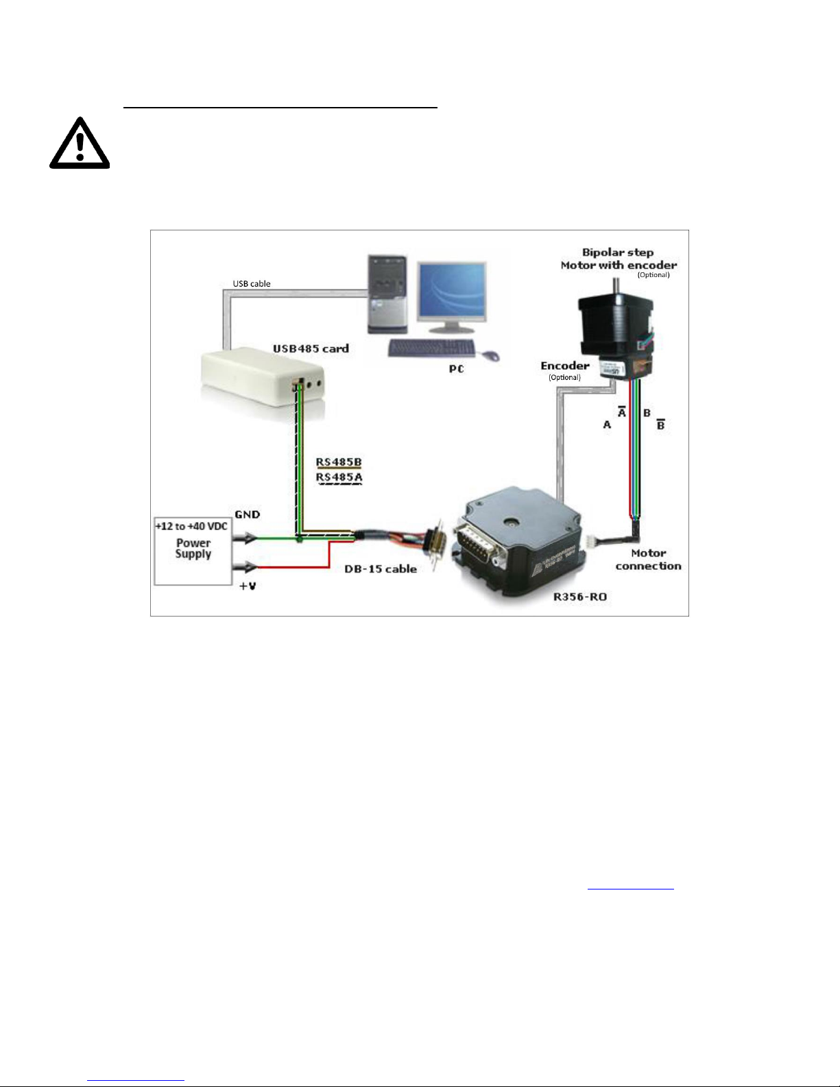
Figure 6: Connection using USB
1. The USB485 converter card connects to the R356 using the DB-15 cable that
is provided to you. The 3-Pin connector is placed onto the converter card.
2. You may refer to the pin assignments on pages 8 and 9.
3. Connect the motor and optional encoder to the R356.
4. Your power supply will be connected to the R356 directly. The USB485 card
is powered via the PC. R356’s pin 9, Red wire is +12 to +40VDC, pin 1,
Green wire is Ground. The USB485 converter card’s Green wire needs
to also connect to the power supply Ground.
5. Connect the USB485 card to your PC using the USB cable provided to you.
You can download the driver for the USB485 from this link: USB485 Driver
6. Turn your power supply on and follow instructions for using Lin Command.
Page 11
R356 Controller & Driver Page 11 Version 1.10
Lin Engineering 3/16/2018
Quick Start
RS232-485 converter card
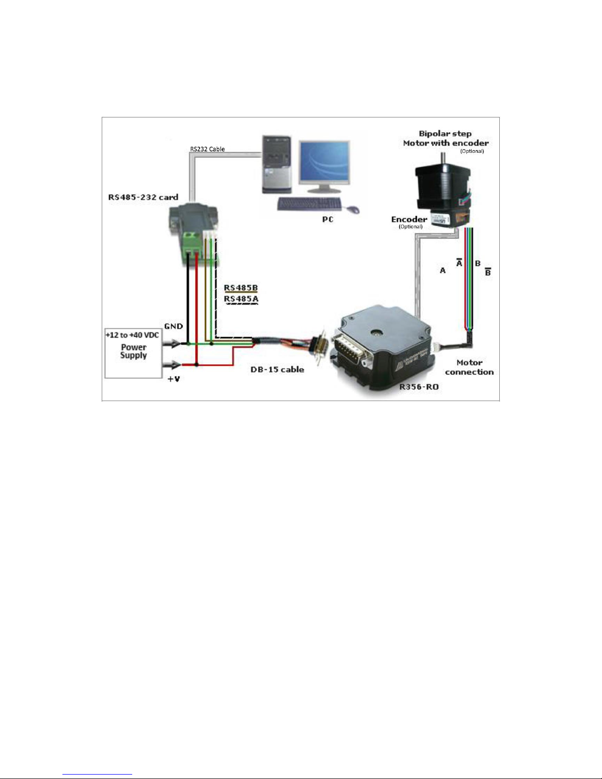
Figure 5: Connection using RS232
1. The RS232 converter card connects to the R356 using the DB-15 cable that is
provided to you. The 3-Pin connector is placed onto the converter card.
R356’s pin 9, Red wire is +12 to +40VDC, pin 1, Green wire is Ground.
The converter card’s green wire needs to also connect to the power
supply Ground.
2. You may refer to the pin assignments on pages 8 and 9.
3. Your power supply will be connected to the RS232 card where the green
header is located. + is for +12 to +40VDC, - is for the Power Supply
Ground.
4. Connect the motor and optional encoder to the R356.
5. Connect the RS232 card to your PC with a male to female DB-9 cable.
6. Turn your power supply on and follow instructions for using LinCommand.
Page 12
R356 Controller & Driver Page 12 Version 1.10
Lin Engineering 3/16/2018
Mating Connectors
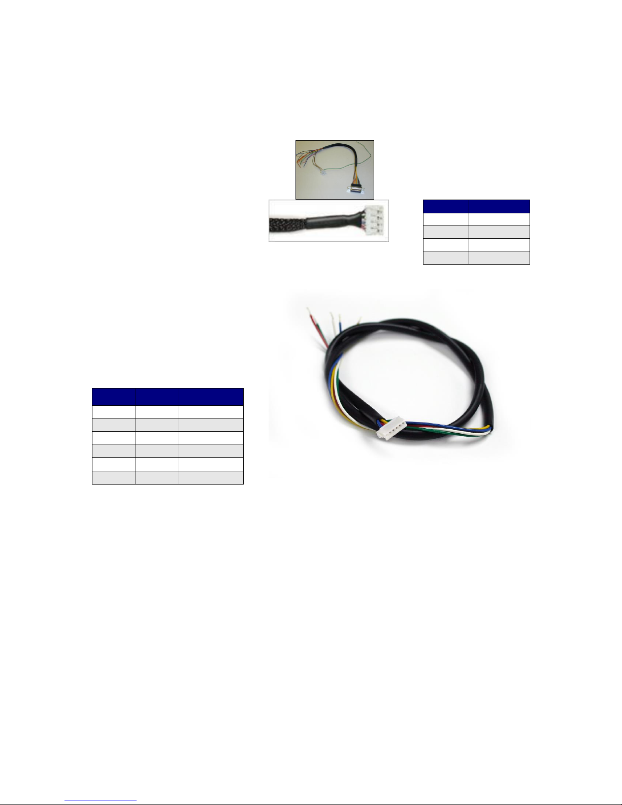
The following cables are provided with the R356 unit (Part # 090-00096):
DB-15 cable:
See page 8 for pin assignments.
4-Pin cable for step motor:
One 4-pin cable is for the motor
windings.
The table to the right depicts
the function
Part # 090-00018
Color
Function
Red
A+ Phase
Blue
A- Phase
Green
B+ Phse
Black
B- Phase
Table 5: Pin description
for Motor
Encoder cable:
This is ideally for a US Digital
E2, E5, or E3 encoder. One
side plugs into the R356. The
opposite side has flying leads
for connection to encoder.
Pin #
Color
Function
1
Green
Ground
2
White
Index
3
Yellow
Ch B
4
Red
+5VDC
5
Blue
Ch A 6 --
--
Table 6: Pinouts for encoder
cable, Part #090-00153
Page 13
R356 Controller & Driver Page 13 Version 1.10
Lin Engineering 3/16/2018
7. CONFIGURING AND CONTROLLING THE R356
LinCommand Setup
For more detailed instructions, please refer to the LinCommand Manual.
Follow these steps to set up and use LinCommand:
Note: If LinCommand has not been installed on your computer, you may download the
program in 32 Bit or, 64 Bit, from one of the links below. After downloading, navigate to the
‘Setup’ file and double click ‘Setup’ to install.
LinCommand 32 Bit
LinCommand 64 Bit
1. After installation, double click on the LinCommand icon ,
to launch the LinCommand program.
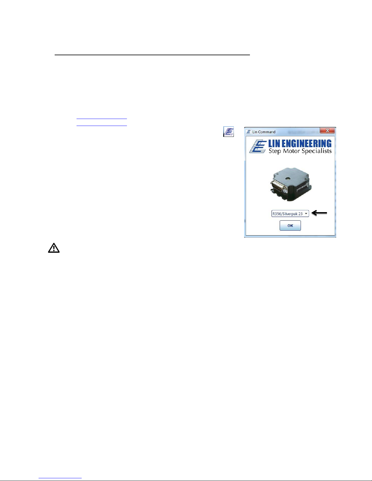
2. Choose your model controller R256 or, R356 from the drop
down box and then click [ OK ].
3. LinCommand opens in ‘Normal’ mode with a GUI interface
for controlling the stepper motor. For Advance mode skip to
step 8 below.
4. To continue in the ‘Normanl’ mode, choose your COM port,
baud rate, and controller address (See Figure 9) and then
click [ Connect ],
Note: if you are using the USB485 converter card, first download
driver files for the USB485
5. Choose the ‘Motor Settings’ tab. Set the Run Current*,
Hold Current, Step Resolution, Velocity, and Acceleration
then click [ Add Settings to Queue ].
CAUTION Do Not Exceed Motors Peak Current or,
Damage to the Motor and Controller Could Result! See “Setting the Current” on following page.
6. Double click on the “Click Here to Add Command” to bring up the motor control menu.
7. For a more instructions, please refer to the LinCommand Manual.
8. To operate in the ‘Advanced mode’, Choose ‘Options’ and select ‘Advanced mode’.
9. Select your COM port and baud rated and then click [ Connect ].
10. Enter command strings on one of the 7 lines in the ‘Send’ window and click ‘Send’ to send
command line to the controller.
11. For a complete list of commands and their definitions refer to the R356 Commands manual.
Example command: /1A10000R
This will run unit #1 to the Absolute position 10000
You can check the address of your driver by checking the dial at the top of the
driver. (See Figure 9)
A full list of commands is available in the Silverpak 23C / R356 Command List
Most common commands to change are:
o Step resolution (/1j2R sets R356 to half stepping)
o Velocity in pulses/sec (/1V1000R sets the speed to 1000 pps)
o Run current (/1m50R sets the run current to 50%)
o Hold current (/1h20R sets the hold current to 20%)
o Move the motor (/1P800R turns the motor 2 revs if half stepping 1.8°)
Page 14
R356 Controller & Driver Page 14 Version 1.10
Lin Engineering 3/16/2018
Responses:
?/0@ indicates good command and that it was received correctly
?/0b indicates bad command
?/0C indicates that the command is out of range
?/0` indicates that the command is terminated
?/0`a Overflow
You may download, “Sample Programs for R256 and R356 controllers”, for additional
program examples.
Setting the Current
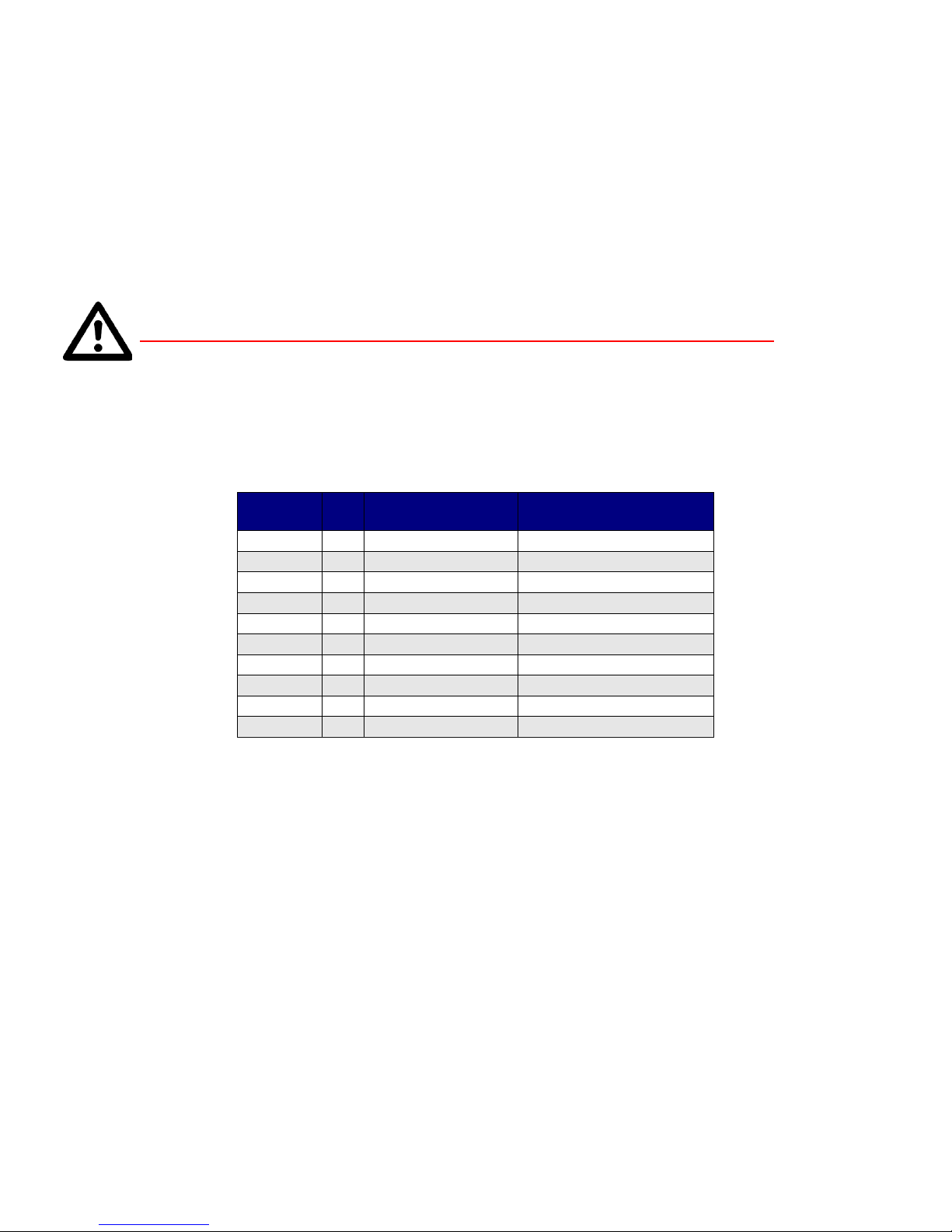
CAUTION! DO NOT SET CURRENT ABOVE THE MOTOR’S RATED CURRENT.
In order to set the correct current for your motor, you must program the specified
amount in LinCommand.
Current is set based on the maximum amount of current the controller board can
output, which is 3.0 Amps Peak. Below is a table of how much current will be
applied to your motor for each setting.
Percent
Motor’s Current
Rating (Amps)
Driver’s Equivalent
Current (Amps)
10%
=
0.21
0.30
20%
=
0.43
0.60
30%
=
0.64
0.90
40%
=
0.86
1.20
50%
=
1.07
1.50
60%
=
1.29
1.80
70%
=
1.50
2.10
80%
=
1.71
2.40
90%
=
1.93
2.70
100%
=
2.14
3.00
Table 5: Desired Current
To achieve the equivalent Driver Current (Amps), multiply your motor’s
rated current by 1.4. Follow these examples:
Example One:
You have a motor that is rated at 0.85 Amps, 0.85 Amps x 1.4 = ~1.2 Amps. Using
Table 5 we would see that 1.2 Amps is 40% of the driver’s maximum output current.
Assuming the R356 is addressed to Number 1, this is what you’d program: /1m40R
Example Two:
You have a motor that is rated at 1.0 Amps, and your Controller is addressed to
Number 1, this is what you’d program: /1m46R
This will set the controller to 1.4 Amps Peak. How did we get 1.4 Amps? 1.0
Amps x 1.4 = 1.4 A Peak.
WARNING!: Setting the current to a value greater than the motor’s rated
current will damage your motor, and may overheat the controller.
Page 15
R356 Controller & Driver Page 15 Version 1.10
Lin Engineering 3/16/2018
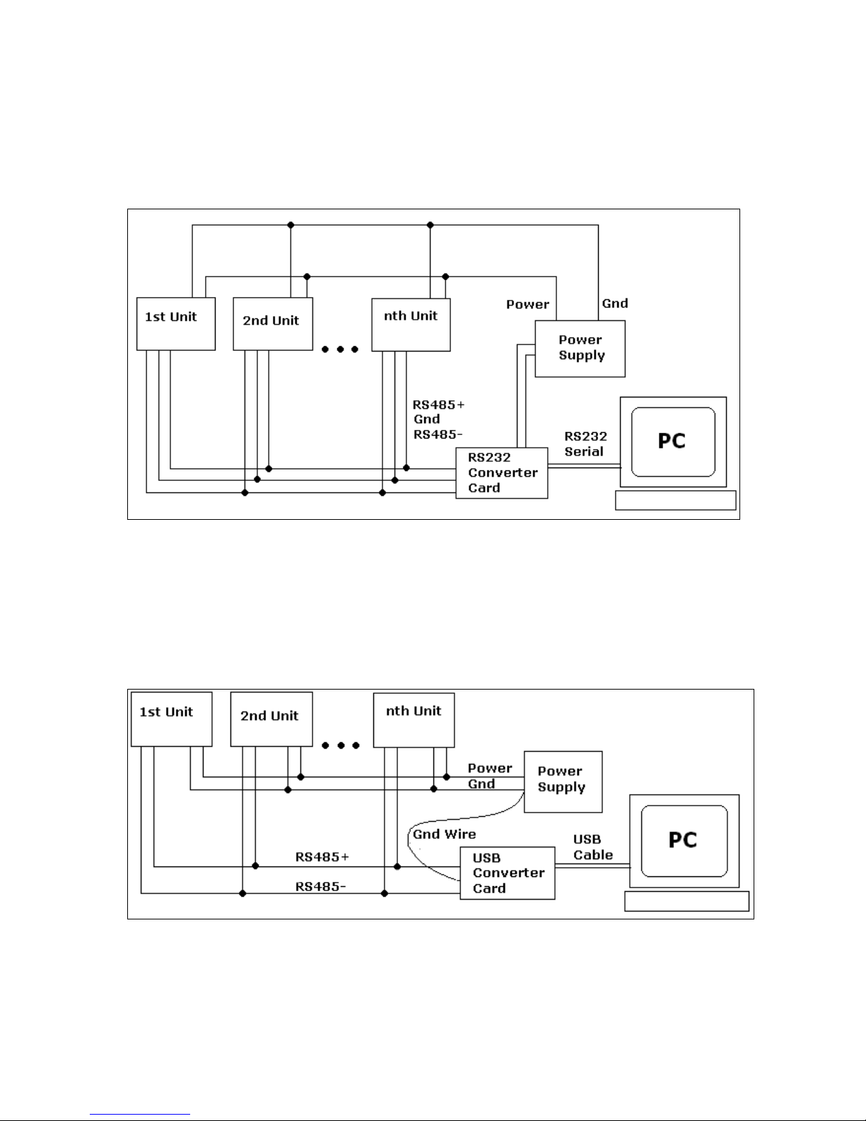
Connecting Multiple R356 Units
Connect multiple units by using the Converter card, shown below. If using the
RS232-to-RS485 converter card, daisy chain all four wires: power, ground, RS485+
and RS485- prior to plugging into the converter card.
Figure 7: Connection using RS232 Converter Card
If using the USB485 converter card, connect all the power and ground lines on the
units to the main power supply. Then daisy chain the RS485+ and RS485- lines
prior to plugging into the USB485 card.
Be sure to also ground the USB485 card with Pin 2, ground.
Figure 8: Connection using USB485Converter Card
Page 16
R356 Controller & Driver Page 16 Version 1.10
Lin Engineering 3/16/2018
Changing the Address of the Controller
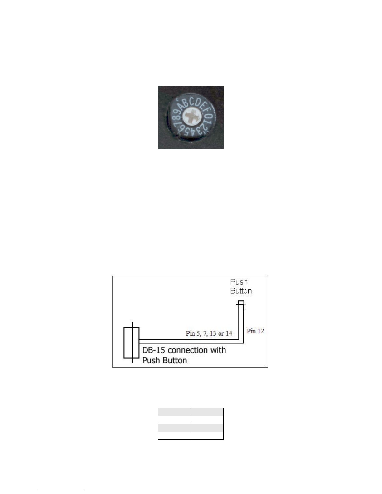
Use a small screwdriver to turn the dial so the arrow points to the desired Address.
Use this number when programming commands. For example, /1P1000R
Figure 9: Address Dial
Connecting Accessories
If you have purchased the Designer’s Kit, there is a Red Push Button and an Optical
Sensor included. Follow the schematics below in order to properly assemble
accessory pieces.
Push Button
Figure 10: Push Button Schematic
Pins 5, 7, 13 and 14 can all be used with push buttons. Below shows the
corresponding input numbers for these pins.
Input 1
Pin 13
Input 2
Pin 5
Input 3
Pin 7
Input 4
Pin 14
Table 7
Page 17
R356 Controller & Driver Page 17 Version 1.10
Lin Engineering 3/16/2018
LED or other output
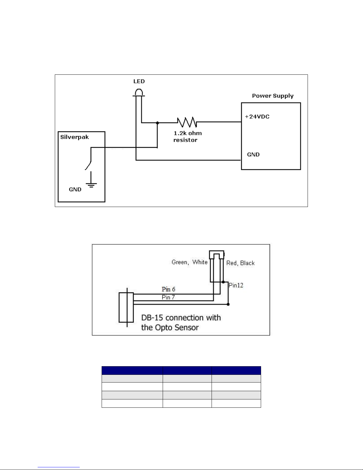
The two driver outputs, pins 2 & 10, can drive an external device such as solenoids,
LED’s, or switches. These outputs are switches that ground internally, and therefore
need to be connected to the +V of the power supply. Below is a recommended
connection for lighting an LED with 20 mAmps:
Upon entering command /1J3R, both pins 2 & 10 will output 1 Amps. The 1.2k ohm
resistor will limit the current to 20 mAmps into the LED. Select any ohm value to
limit your current based on the device that is connected to the output.
Optical Sensor
Figure 11: Opto Sensor Connection Schematic
Use the following table to connect the corresponding wires.
Optical Sensor
DB15 Cable
Pin #
Green
Green/white
12
Black
Green/white
12
Red
Yellow/white
6
White
Orange/white
7
Table 8
Pin 2
or 10
output
Page 18

R356 Controller & Driver Page 18 Version 1.10
Lin Engineering 3/16/2018
Appendix A
Encoder Usage
The R356 can do closed loop position correction. The encoder connects to the board
internally.
Position Correction Mode
Position correction mode, when enabled will issue steps to the motor until the
encoder reads the correct position. Once enabled, positions are given in
Quadrature encoder counts of the encoder – not in microsteps. If the motor
stalls during a move then this mode will reattempt the move until the encoder reads
the correct number, or until it has tried a certain number of times and times out.
First: Set the Encoder Ratio:
Encoder ratio = [(Microstep * 200 steps/rev) / (CPR *4)]*1000
This must be a whole number after you multiply by 1000.
For example: a 1.8° motor set to 256x microstepping with a 1000 count encoder:
Encoder ratio = ((200 * 256)/(1000*4))*1000 = 12800
Set encoder ratio: /1aE12800R
If Encoder Ratio is Unknown:
Follow these steps:
1. Issue a /1n0R to clear any special modes
2. Issue a /1z0R to set position of encoder and controller to zero
3. Issue a /1A100000R and ensure the move completes at a velocity that does
not stall.
4. Issue a /1?0 to read current position. This should be 100000.
5. Issue a /1?8 to read the encoder position
6. Issue a /1aE0R which auto divides these two numbers
7. Issue a /1?aE which read backs the encoder ratio computed
8. This value is a rough guide and may be a few counts off due to inaccuracies in
the motor position and run-out of the encoder, but use the EXACT number
that was returned and set it with a /1aEXXXXR. Or, please contact Lin
Engineering and provide us with your motor part number and we can look up
the encoder CPR for you.
Second: Set the Error in Quadrature Encoder Ticks allowed before correction begins:
/1aC50R (default is 50) Motor will move 50 encoder ticks away from desired position
before position correction takes place. If aC is set to too small of a value, the motor
may oscillate back and forth trying to locate the exact position. Use a larger aC
value.
Third: Set the Overload Timeout Value:
This is the number of re-tries allowed under a stall condition: /1au10000R (default
is 10)
Fourth: Enable the Feedback mode:
Zero the positions prior to enabling the feedback mode: /1z0R
Issue /1n8R to enable the feedback mode.
Page 19

R356 Controller & Driver Page 19 Version 1.10
Lin Engineering 3/16/2018
Overload Report Mode
Overload report mode when enabled, will compare the encoder value to the
commanded position at the end of a move and report an error if the two values do
not match within the range given by “aC”. When this error occurs the drive will exit
from any loops or strings it may be executing.
Overload report mode is enabled by /1n16R, and requires the encoder ratio to be
entered correctly via the “aE” command. Issue a /1zR to zero both the encoder and
position counter just prior to issuing /1n16R. Only the Position Correction mode or
the Overload Report mode may be turned on at one time.
Notes:
1. When any command is received by the drive it will always respond with its
status. The drive will only accept a command when it is not busy. This status
byte received must be checked to ensure that the unit was not busy and that
the command was accepted. This is especially important when position
correction mode is enabled, because the drive may be attempting to correct
position all by itself, and will reject an externally (via RS232) received
command if it is busy in the middle of a correction move.
2. When position correction mode is enabled, /1n8R, then the drive will keep
retrying any stalled moves, and will NOT halt any strings or loops upon
detection of a stall.
3. During position correction mode /1T will halt any move, but there is a
possibility that the drive may instantly reissue itself a position correction
command, especially if it is fighting a constant disturbance. It may be
necessary to issue a /1n0R to positively halt a move in progress.
4. Position correction mode is inhibited if the encoder underflows and goes
negative (but will automatically resume if a move is made into the positive
range). If position correction is required at the zero point, please redefine
zero to be a slightly positive number with the “z” command. Eg /1z10000R
5. If the encoder ratio is changed from its default of 1000, the allowed max
position will be decreased from +2^31 by the same ratio.
Appendix B
Peak current versus Amps/Phase
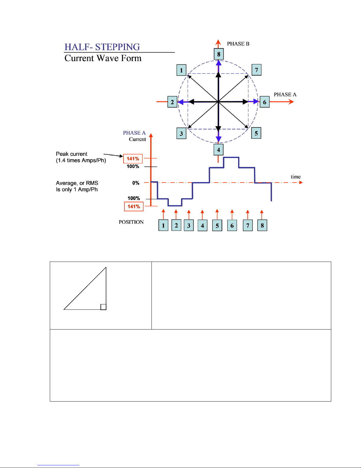
Where does the 1.4 times come from? Current is continuously changing when a
motor steps. If the motor is rated for 1.0 A/Ph, it may receive 0 Amps, 1 Amp, 1.4
Amps, or anything in between if you are microstepping. For ease of explanation, we
will look at the current waveform when we half step, or set the driver/controller to
2x microstepping.
If we take a look at both the A and B phases, and plot on an X-Y chart of when each
phase receives current, and how much it receives, it will look like the chart below.
Beginning at position 1, Phase A receives negative current, and Phase B receives
positive current. Let’s assume it is at coordinate (-1, 1).
Page 20
R356 Controller & Driver Page 20 Version 1.10
Lin Engineering 3/16/2018
The position versus time graph just above, plots only the A Phase, following the eight
different steps the motor will make. Current is changing with each position. Recall
that a negative in electronics simply means reverse direction of current flow.
Take a look at position #7. If we were to draw the arrow
at position 7 as the hypotenuse of a triangle, it would
look like the triangle to our left. Recall from geometry a
90°-45°-45° triangle is a 1-1-√2 combination. The √2,
or 1.4 value is also the radius of the dotted circle shown
above. Therefore, during certain steps, Phases A or B will
receive 1.4 Amps of current. But the average, or RMS
current throughout these 8 steps is only 1.0 Amps. RMS
and Amps/Phase is the same meaning.
The 1.4A along this hypotenuse is also known as the 2-Phase On position, since both A and
B Phases are “On” and receive current. It is also known as the peak current.
As we see the waveform that’s plotted for the A Phase, the highest value on the curve is
known as the peak value.
Motors have a rated current, or average RMS value since in operation, the current is
continuously changing. The most logical way to describe a rating is to take an average, or
RMS (root means squared) value. But drivers understand current in terms of peak current,
therefore the conversion is: Amps/Phase x 1.4 = Amps Peak
1.41 AMP
1 AMP
(√2)
Page 21
R356 Controller & Driver Page 21 Version 1.10
Lin Engineering 3/16/2018
Appendix C
Step and Direction Mode
The R356 unit can be configured as a driver only by first connecting it to your PC and
saving the special mode “n96” in program memory storage zero.
1. First connect to your PC and save n96 in storage zero:
/1s0n96R
2. Next, connect the positive side of a TTL squarewave for step pulses to Pin 11
(Blue/white wire).
3. Connect a +5VDC supply to Pin 4 (Yellow wire).
4. Tie together the negative pin of the step pulse to the negative 5VDC supply.
This becomes your signal ground.
5. Change direction of rotation on the fly by connecting or disconnecting Pin 3
(White/green wire) to the signal ground that was just created in Step 4.
The unit can still accept commands via RS485 when in step & direction mode, but
move commands via RS485 will override step pulses.
Appendix D
Motor Connections (Does not apply to SilverPak motors)
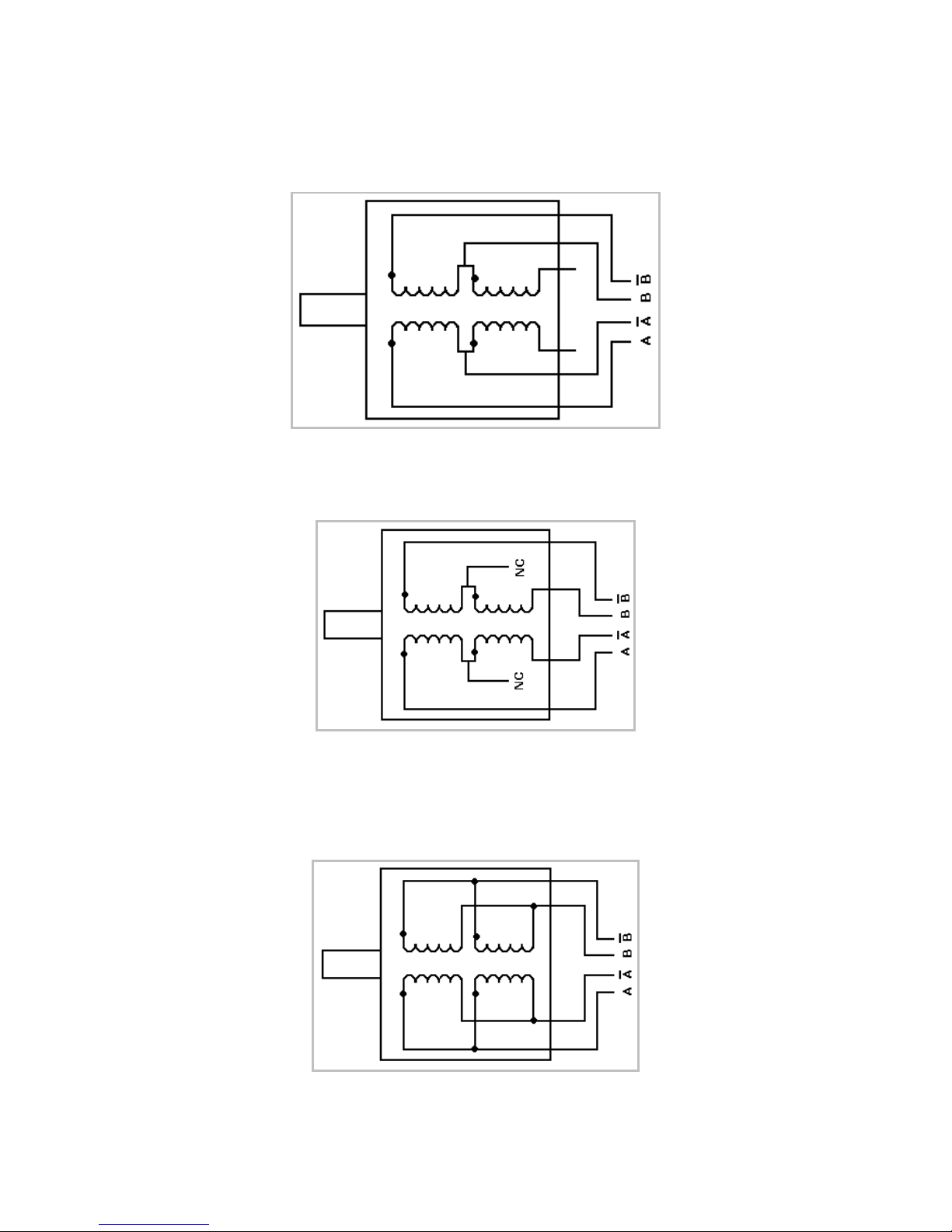
Step Motors have 4, 6, or 8 wires. To better understand how to connect your step
motor with your R356 Controller, follow the Figures below for the corresponding
motor. NOTE: The dots indicate the starting position of the wires when wound.
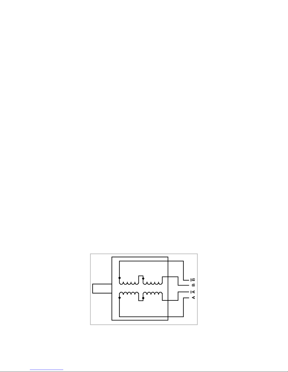
4 Lead Wire Motor Connection
Connect one set of windings to the A terminals. Connect the other set of windings to
the B terminals. If the set of windings is unclear, take a pair of wires; use an
ohmmeter to check for continuity. When you find the first two wires that have
continuity, connect it to the A terminals. Connect the other two to the B terminals.
Figure 18: 4 Lead Wire Motor Connection
Page 22
R356 Controller & Driver Page 22 Version 1.10
Lin Engineering 3/16/2018
6 Lead Wire Motor Connection (Half Winding)
Six wire motors can be wound in two ways: Half Winding and Full Winding. Six wire
motors contain a center tap on each of the two windings. For a half-winding
connection, the center tap and one end of the wires are used.
Figure 19: 6 Lead Wire Half Winding Connection
6 Lead Wire Motor Connection (Full-Winding)
For a full winding connection, use both end wires, the center tap is ignored. (NC: No
Connection).
Figure 20: 6 Lead Wire Full Winding Connection
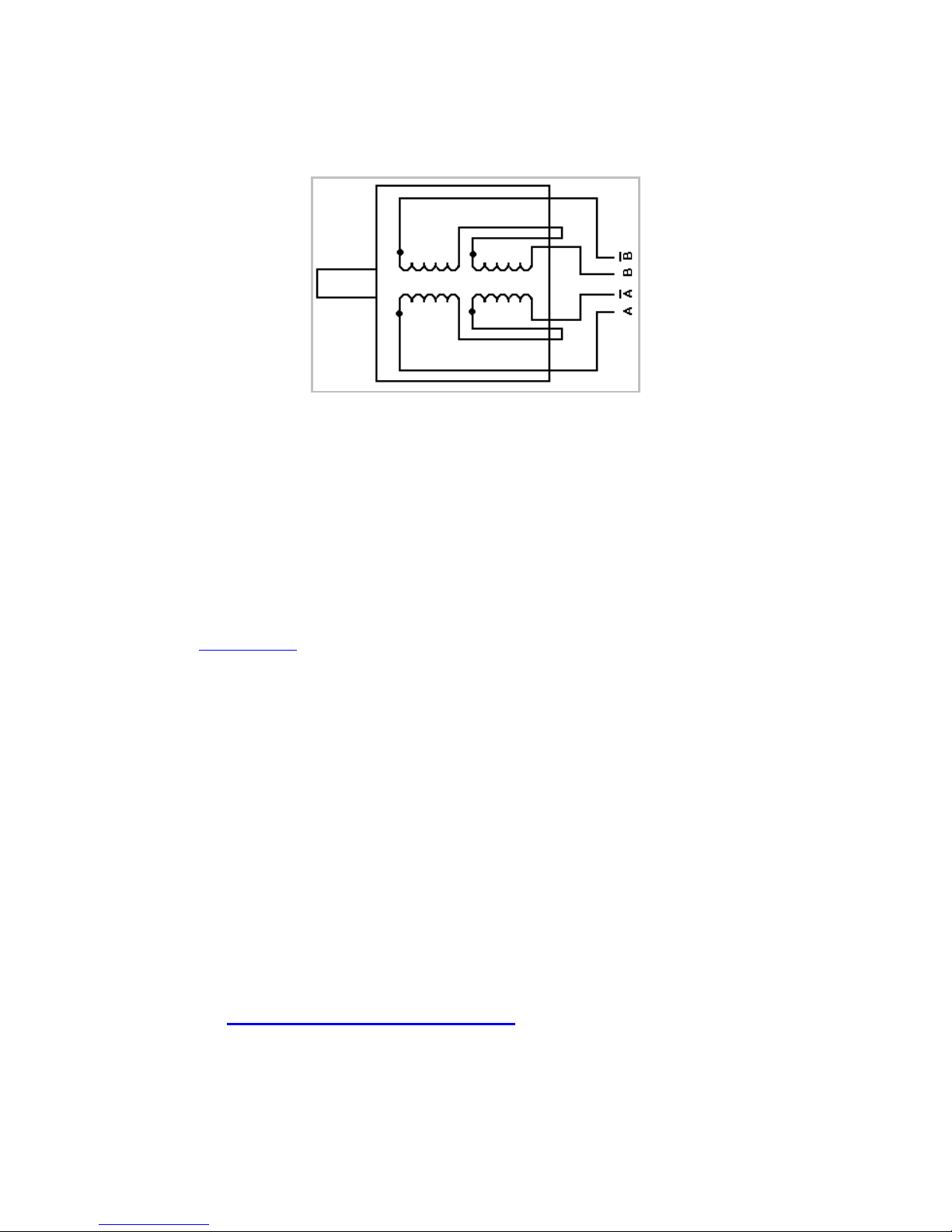
8 Lead Wire Motor Connection (Parallel Connection)
Eight wire motors can be connected in two ways: Parallel and Series. When in
parallel, the wires are simply connected such that the beginning of each winding are
connected together.
Figure 21: 8 Lead Wire Parallel Connection
Page 23
R356 Controller & Driver Page 23 Version 1.10
Lin Engineering 3/16/2018
8 Lead Wire Motor Connection (Series Connection)
Be sure to set the drive current to exactly half of the motor’s rated parallel current
rating when using the series connection.
Figure 22: 8 Lead Wire Series Connection
Appendix E
Troubleshooting
USB485 interface card driver not communicating
Reinstall USB485 driver
Disconnect the USB485 from the computer and driver
Go to Windows Device Manager
Uninstall USB485 (RMS Tech…)
Restart computer
Go to USB485 Driver
Verify the ‘USB485 diver’ folder is in the downloads folder
Plug the USB485 back into the computer, but not the driver
Go to Device Manager, expand Universal Serial Bus controllers
Right Click USB485, Choose ‘Properties’
Select “Driver” tab and choose “Update Driver”
Browse to ‘Downloads’ folder, click USB485 and choose ‘Next’
This should correct any USB485 driver problems.
Hardware Troubleshooting
Carefully re-check all instructions for hardware and wiring diagrams.
Many times problems are related to wiring and/or connector issues.
Technical Support
By Telephone: 408-919-0200 (Mon.-Fri., 8:00 a.m.-5:00 p.m. Pacific Time)
By Email: [email protected]
On the Web: www.linengineering.com
Our technical support group is glad to work with you in answering your questions. If
you cannot find the solution to your particular application, or, if for any reason you
need additional technical assistance please contact us.
 Loading...