

Page 1
TREADLITE II Cat. No. T-91-SCE Foot Operated Switch
r
)
)
e
r
CLASSIFICATION ==================================================================
RATINGS: 16(4)A 250 VAC~ 50/60 HZ FREQUENT OPERATION: +++ 1E5
16A ½ HP 125-250 VAC~ ACTUATING METHOD: FOOT OPERATED
EARTHING (GROUNDING): CLASS I CATEGORY A
MICRO DISCONNECTION: µ PROOF TRACKING INDEX: PTI 175
ENVIRONMENT: IP20, NEMA TYPE 1
SUITABLE FOR USE IN A NORMAL SITUATION (ORDINARY LOCATION).
NOTE: THIS IS NOT A MAINS DISCONNECT DEVICE.
WIRING ==========================================================================
1. WARNING: TO AVOID PERSONAL INJURY, DO NOT USE THIS SWITCH ON MACHINERY WITH AN
UNGUARDED POINT OF OPERATION.
READ WARNING STATEMENT on reverse side of this page.
2. When wiring up this device make sure POWER IS OFF AND LINES ARE DEAD.
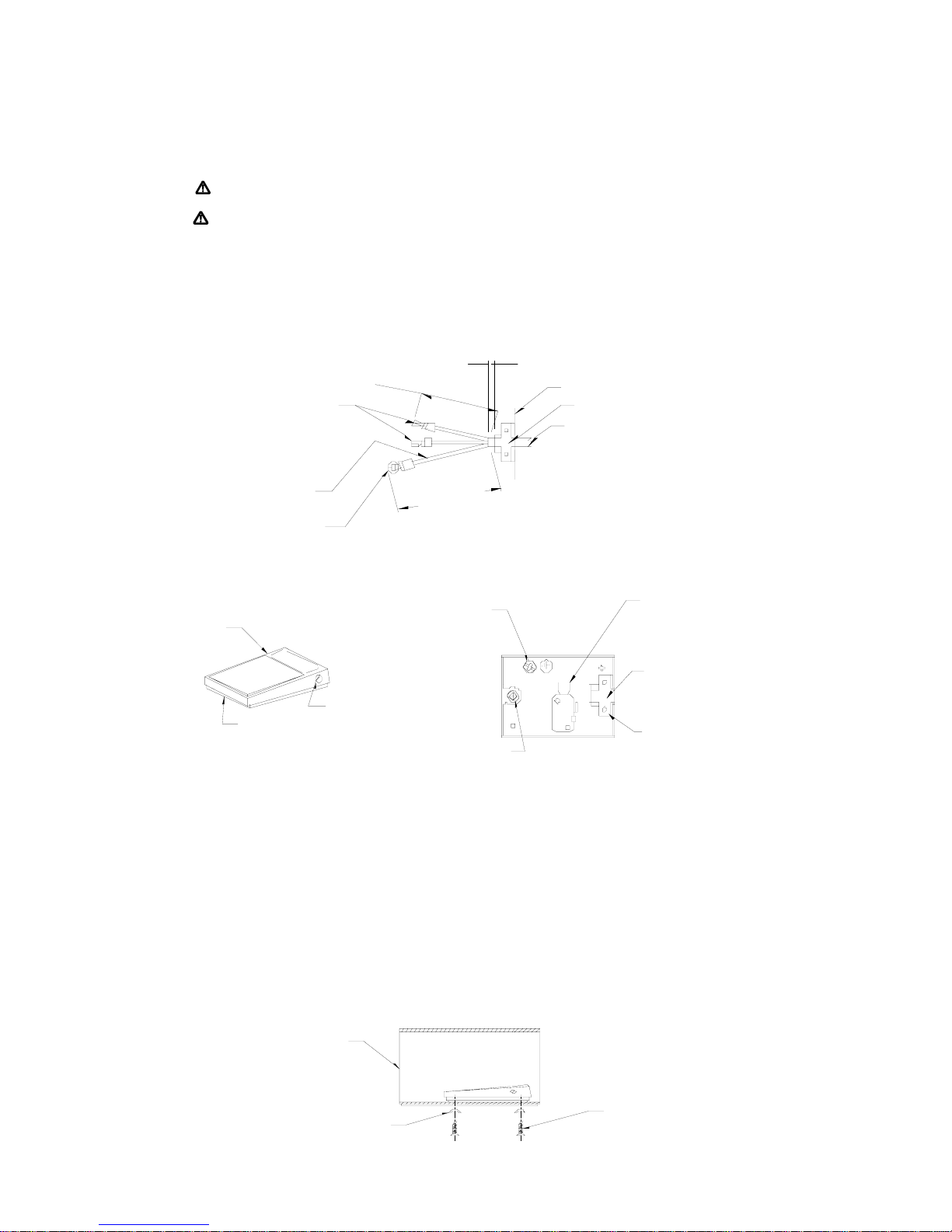
3. Supply cord with flexible conductors (leads) to be prepared as shown. (See Diagram "A")
Supply cord with prepared flexible conductors. Use special purpose crimping tools to apply female quick-connect and
ring
terminal to conductors. Insulation support type terminals required. The female quick-connect terminals must be
insulated.
FOR CE MARKED SWITCHES, PLEASE NOTE THE FOLLOWING:
-The grounding conductor must be green or green/yellow in color.
-A cord guard or bend relief must be provided that extends beyond the cord clamp at least five times the overall diameter
of the flexible cord.
6.3 x 0.8mm (1/4 IN.) female
quick-connect terminal.
Note: Quick-connect
terminals must be insulated.
50.8mm (2IN.)
Green / Yellow
RING TYPE TERMINAL
4. Remove hinge screws and detach cover and cover return spring from base. (See Diagram "B").
5. Loosen or remove cord clamp screws, insert cord and connect inner conductors (leads) of cord to appropriate switch
terminals. (See Diagram "C")
Cover
4mm Ø (#8
Pr ot ec tive eart hin g (Grou nd in g)
terminal with lockwa sh er.
Ti ghten ter m i nal s cr ew 1. 2 t o
1. 8Nm (11 to 16 IN-LBS )
146.05mm
(5 .75 IN.
3.2mm ( 1/8 IN.)
DI AGRAM "A "
Base
Cord Clamp
Use 3 conductor cord for single pole
normally open or normaly closed
operation. Maxim um flexible conducto
size: 1.5 mm
Use UL/CSA constructed cordage for
Nor th American applications and
Har monized corda ge for International
applications.
2
(#14 AWG)
6.3 x 0.8mm (1/4 IN. ) flat
quick c onnect ta bs for sw i tch
terminations.
Co rd clamp ac cept s c or d
N.C. N.O.
Hin ge s crew with lock
Bas
DIAGRAM "B"
6. Re-assemble cover return spring and cover to base with hinge screws.
7. CLEANLINESS must be observed during installation and in use.
On a REGULAR BASIS inspect foot switch frequently to guard against wear, damage, unlawful alterations or removal
of guards, or for unusual enclosure deterioration and the like. Inspect the entire length of the connecting cord (or wiring
system) from where it enters the foot switch to the equipment it's wired up to for wear, loose strain relief connections
and the like. DO NOT OPERATE the foot switch if any of the above is observed or if the nameplate or warning label
has been obscured or removed.
It is IMPERATIVE that inspection authorities and users exercise more than ordinary care with regard to installation and
maintenance and that this information sheet be made available to the end user, operators, maintenance personnel and
to others responsible for proper installation and safe operation of this foot switch.
ADDITIONAL COPIES of this information sheet and warning labels are available upon request.
MOUNTING =======================================================================
1. Treadlite II foot operated switches are furnished with a non-skid base pad and can be mounted with the base pad
attached.
2. Use two number 4 thread-cutting (self-tapping) screws and two number 4 lock washers when mounting to full guard
(See Diagram “D”).
#5 22 -B 14 Fu ll g uard w ith
assembly hardware and
instr uc tions availab le up on
re qu es t.
w ashe r. T ighten to 1.6 to
1. 8Nm (14-16 IN-LBS).
#4 L ock w ash e
Cov er Return Sp ri n g
DIAGRAM " C"
COM
sizes 6 to 11mm Ø (.250 to
.4 35 diameter ).
Ti ghten c ord cl amp s crew s
alte rnatel y 1.4 t o 1.6 Nm (12
to 14 IN-LBS).
#4 Flat head thread-cutting
sc r ew
DIAG RAM “D ”
Form 515-D27 Rev. D
Page 2

WARNING
USE OF FOOT CONTROLS ON MACHINERY LACKING EFFECTIVE POINT
OF OPERATION SAFEGUARDS CAN CAUSE SERIOUS INJURY TO THE
OPERATOR.
Foot controls should only be used where “Point of Operation” and “Pinch
Point” guarding devices have been properly installed and are utilized so that it
is IMPOSSIBLE for the operator’s hands or fingers to remain within the point
of operation during the machine cycle.
Form 515-D27 Rev.
IT IS THE RESPONSIBILITY OF THE USER to determine the suitability of a
foot control for the user’s intended use and to determine that the foot control
chosen by the user and wiring up and installation of same will comply with all
Federal, State and Local safety and health regulations and codes.
Due to the unlimited variety of business equipment, instruments, machines
and vehicles on which our foot switches are used, the thousands of standards,
and customers’ varying interpretations of the standards covering these
applications, it is impossible for LINEMASTER personnel to be experts on
standards and requirements for all these products. We offer over 150 stock
foot switch models and guards plus a large variety of specials which are made
to customer specifications. We can advise you what is available in our foot
switch line and you can examine models to see what meets your needs. We
believe our customers’ engineering departments should be the qualified
experts in their own product field and know what specifications or details they
may require in a foot switch for their equipment. If one of our stock models
meets their needs, they can specify it, or possibly ask for a modification of a
stock model if that is required.
SHOULD YOU HAVE ANY QUESTIONS OR IF ANY OF THE ABOVE
WARNING IS UNCLEAR, PLEASE CALL LINEMASTER SWITCH
CORPORATION. (860) 974-1000; FAX (860) 974-0691
READ INSTRUCTIONS on reverse side of this page.
DEFINITIONS:
POINT OF OPERATION - The point or area of the machine or equipment
where the work piece or material is actually positioned and work is being
performed during any process such as cutting, shearing, punching, forming,
welding, riveting, assembling, etc..
PINCH POINT - Any point at which it is possible for a portion of the body to be
caught and injured between moving machine or equipment or work piece
parts.
Page 3

Form 515-D27
Paper Size:
Notes:
Black printing on white paper, with English Warning on outside.
Drawn by Date Approved by
T.J.F. 02-14-00 R.D.C. 02-14-00
Revision Letter Date
B 02/14/00 Added CE paragraph, revised stripping for changes with
C 10-24-08 Reactivated and redrawn/retyped. (ECN 0800382)(KG)
D 06-18-09 See revision page @ F:\Files\Revision Pages\515
10” x 24”
Folded Size:
new insert. (ECN 004698) (TJF)
2.500 x 3.000
Date:
Description
 Loading...