

Page 1

W
s
查询J174供应商
J/SST174 SERIES
SINGLE P-CHANNEL
Linear Integrated Systems
JFET SWITCH
FEATURES
Direct Replacement For SILICONIX J/SST174 SERIES
LOW ON RESISTANCE r
LOW GATE OPERATING CURRENT I
ABSOLUTE MAXIMUM RATINGS1
@ 25 °C (unless otherwise stated)
Maximum Temperatures
Storage Temperature -55 to 150°C
Junction Operating Temperature -55 to 135°C
Maximum Power Dissipation
Continuous Power Dissipation 350mW
Maximum Currents
Gate Current IG = -50mA
Maximum Voltages
Gate to Drain Voltage V
Gate to Source Voltage V
DS(on)
D(off)
GDS
GSS
≤ 85Ω
= 10pA
= 30V
= 30V
J SERIES
TO-92
BOTTOM VIE
DGS
123
SST SERIES
SOT-23
TOP VIEW
1
D
3
2
S
G
COMMON ELECTRICAL CHARACTERISTICS @ 25 °C (unless otherwise stated)
SYMBOL CHARACTERISTIC MIN TYP MAX UNITS CONDITIONS
BV
Gate to Source Breakdown Voltage 30 IG = 1µA, VDS = 0V
GSS
V
Gate to Source Forward Voltage -0.7
GS(F)
I
Gate Reverse Current 0.01 1 VGS = 20V, VDS = 0V
GSS
IG Gate Operating Current 0.01 VDG = -15V, ID = -1mA
I
Drain Cutoff Current -0.01 -1
D(off)
V
nA
IG = -1mA, VDS = 0V
VDS = -15V, VGS = 10V
SPECIFIC ELECTRICAL CHARACTERISTICS @ 25 °C (unless otherwise stated)
SYMBOL CHARACTERISTIC
V
GS(off)
I
r
DS(on)
DSS
Gate to Source
Cutoff Voltage
Drain to Source
Saturation Current
Drain to Source
On Resistance
J/SST174 J/SST175 J/SST176 J/SST177
MIN MAX MIN MAX MIN MAX MIN MAX
5 10 3 6 1 4 0.8 2.25 V V
-20 -135 -7 -70 -2 -35 -1.5 -20 mA VDS = -15V, VGS = 0V
85 125 250 300 Ω VGS = 0V, VDS = -0.1V
UNITS CONDITIONS
= -15V, ID = -10nA
DS
Linear Integrated System
• 4042 Clipper Court • Fremont, CA 94538 • Tel: 510 490-9160 • Fax: 510 353-0261
Page 2
s
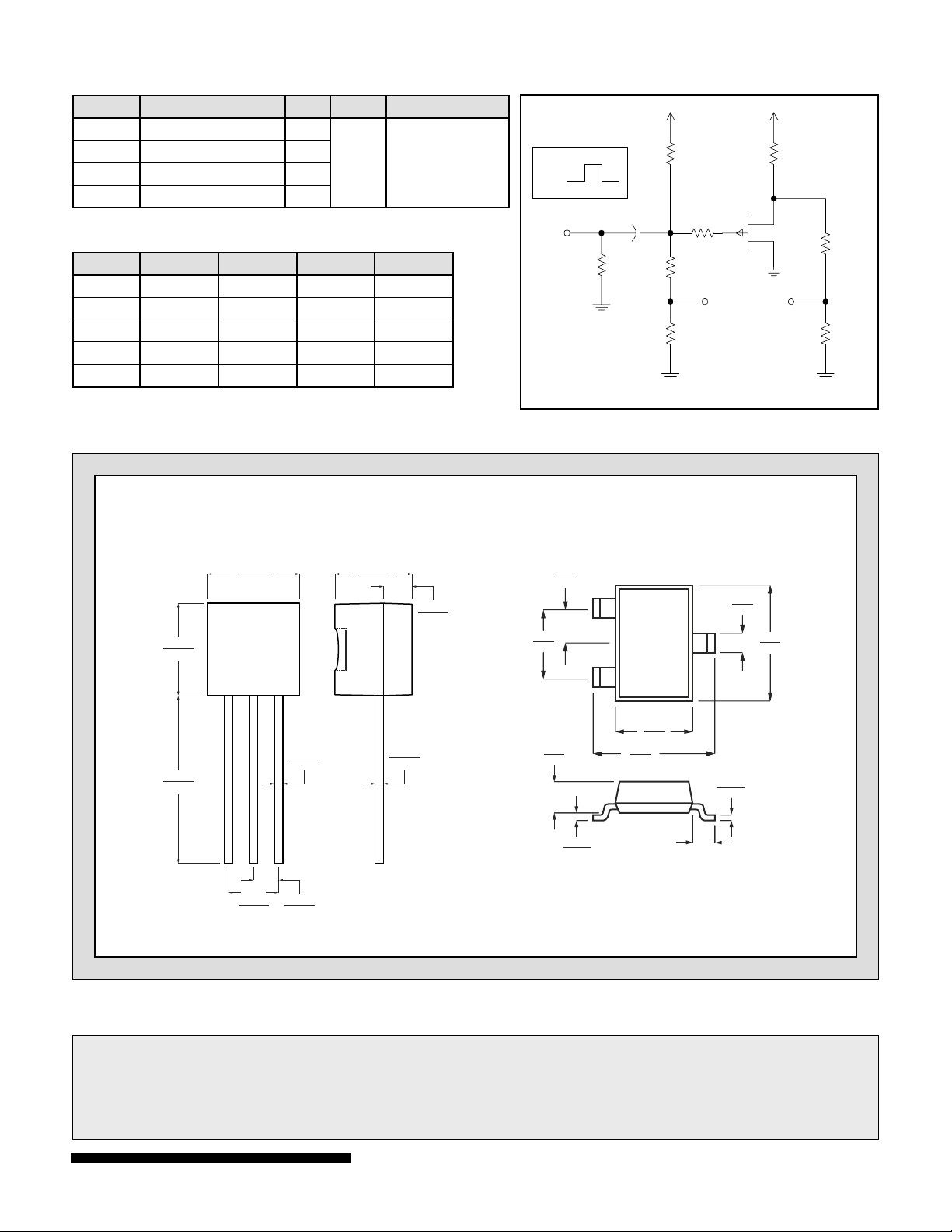
SWITCHING CHARACTERISTICS
SYMBOL CHARACTERISTIC TYP UNITS CONDITIONS
t
Turn On Time 10
d(on)
tr Turn On Rise Time 15
t
Turn Off Time 10
d(off)
tf Turn Off Fall Time 20
ns
V
= 0V
GS(L)
= 10V
V
GS(H)
See Switching
Circuit
SWITCHING CIRCUIT PARAMETERS
J/SST174 J/SST175 J/SST176 J/SST177
VDD -10V -6V -6V -6V
VGG 20V 12V 8V 5V
RL 560Ω 750Ω 1800Ω 5600Ω
RG 100Ω 220Ω 390Ω 390Ω
I
-15mA -7mA -3mA -1mA
D(on)
SWITCHING CIRCUIT
1.2k
0.1µF
1.2k
51
Ω
Ω
Ω
V
GS( H)
V
GS( L)
51
Ω
R
L
R
G
7.5k
Ω
Scope
51
Ω
0.170
0.195
0.500
0.610
TO-92
0.175
0.195
LS XXX
YYWW
123
0.095
0.105
0.016
0.022
0.045
0.055
0.130
0.155
DIMENSIONS
IN INCHES.
0.014
0.020
0.045
0.060
1.78
2.05
0.89
1.12
SOT-23
0.89
1.03
1
2
0.013
0.100
1.20
1.40
2.10
2.64
0.55
DIMENSIONS IN
MILLIMETERS
0.37
0.51
0.085
0.180
2.80
3.04
3
1. Absolute maximum ratings are limiting values above which serviceability may be impaired.
2. Pulsed test: PW ≤ 300µS Duty Cycle: 3%
Information furnished by Linear Integrated Systems is believed to be accurate and reliable. However, no responsibility is assumed for its
use; nor for any infringement of patents or other rights of third parties which may result from its use. No license is granted by implicatio
otherwise under any patent or patent rights of Linear Integrated Systems.
n or
Linear Integrated System
• 4042 Clipper Court • Fremont, CA 94538 • Tel: 510 490-9160 • Fax: 510 353-0261
 Loading...