

Linear Technology RH1009 Datasheet
DUESCRIPTIO
A
U
G
W
A
WUW
ARB
S
O
LUTEXI T
I
S
WU
U
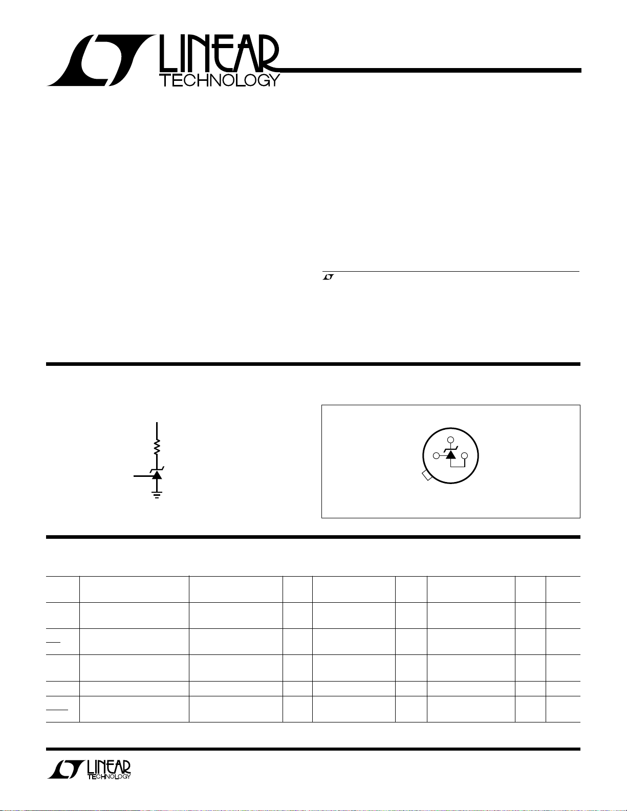
PACKAGE
/
O
RDER I FOR ATIO
BOTTOM VIEW
ADJ
–
+
H PACKAGE
3-LEAD TO-46 METAL CAN
RH1009
2.5V Reference
The RH1009 is a general purpose 2.5V shunt regulator
diode designed to operate over a wide current range while
maintaining good stability with time and temperature. The
adjust terminal allows either temperature coefficient to be
minimized or the reference voltage to be adjusted without
changing the temperature coefficient. Because it operates
as a shunt regulator it can be used equally well as a positive
or negative reference.
The wafer lots are processed to Linear Technology’s inhouse Class S flow to yield circuits usable in stringent
military applications.
U U
BUR -I CIRCUIT
20V
2k
NC
Reverse Breakdown Current ................................ 20mA
Forward Current................................................... 10mA
Operating Temperature Range ............. –55°C to 125°C
Storage Temperature Range ................. –65°C to 150°C
Lead Temperature (Soldering, 10 sec)..................300°C
, LTC and LT are registered trademarks of Linear Technology Corporation.
TABLE 1: ELECTRICAL CHARACTERISTICS (Preirradiation)
SYMBOL PARAMETER CONDITIONS NOTES MIN TYP MAX GROUP MIN TYP MAX GROUP UNITS
V
Z
∆V
Z
∆I
R
r
Z
∆V
Z
∆V
Z
∆Time I
RH1009 BI
TJ = 25°C SUB- SUB-
Reverse Breakdown IR = 1mA 2.495 2.505 1 V
Voltage
Reverse Breakdown 400µA ≤ IR ≤ 10mA 6 1 10 2,3 mV
Voltage Change with Current
Reverse Dynamic IR = 1mA 1 0.6 1 Ω
Impedance
Temperature Stability 1 15 mV
Long Term Stability TA = 25°C±0.1°C, 20 ppm/kHr
= 1mA
R
Information furnished by Linear Technology Corporation is believed to be accurate and reliable.
However, no responsibility is assumed for its use. Linear Technology Corporation makes no representation that the interconnection of its circuits as described herein will not infringe on existing patent rights.
–55°C ≤ TJ ≤ 150°C
1
RH1009
TABLE 1A: ELECTRICAL CHARACTERISTICS (Postirradiation) (Note 2)
20KRAD(Si)10KRAD(Si)
SYMBOL PARAMETER CONDITIONS NOTES MIN MAX MIN MAX MIN MAX MIN MAX MIN MAX UNITS
V
∆V
∆I
r
Z
Note 1: Guaranteed by design, characterization or correlation to other
tested parameters.
TOTAL DOSE BIAS CIRCUIT
Reverse Breakdown IR = 1mA 2.495 2.505 2.495 2.505 2.495 2.505 2.495 2.505 2.495 2.505 V
Z
Voltage
Reverse Breakdown Voltage 400µA ≤ IR ≤ 10mA 6 6 8 10 12 mV
Z
Change with Current
Z
Reverse Dynamic IR = 1mA 1 0.6 0.6 0.8 1.0 1.4 Ω
Impedance
Note 2: T
15V
12.4k
= 25°C unless otherwise noted.
A
RH1009 TDBC
U
W
50KRAD(Si)
100KRAD(Si) 200KRAD(Si)
TABLE 2: ELECTRICAL TEST REQUIRE E TS
MIL-STD-883 TEST REQUIREMENTS SUBGROUP
Final Electrical Test Requirements (Method 5004) 1*,2,3
Group A Test Requirements (Method 5005) 1,2,3
Group C and D End Point Electrical Parameters 1
(Method 5005)
* PDA Applies to subgroup 1. See PDA Test Notes.
PDA Test Notes
The PDA is specified as 5% based on failures from group A, subgroup 1,
tests after cooldown as the final electrical test in accordance with method
5004 of MIL-STD-883 Class B. The verified failures of group A, subgroup
1, after burn-in divided by the total number of devices submitted for burnin in that lot shall be used to determine the percent for the lot.
Linear Technology Corporation reserves the right to test to tighter limits
than those given.
UW
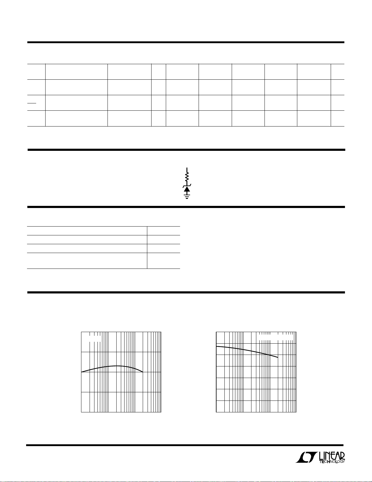
TYPICAL PERFORMANCE CHARACTERISTICS
Reverse Breakdown Voltage
2
Reverse Breakdown Voltage
2.502
IR = 1mA
2.501
2.500
2.499
REVERSE BREAKDOWN VOLTAGE (V)
2.498
1
10 100 1000
TOTAL DOSE KRAD (Si)
RH1009 G01
Linear Technology Corporation
1630 McCarthy Blvd., Milpitas, CA 95035-7417 ● (408) 432-1900
FAX: (408) 434-0507
●
TELEX: 499-3977 ● www.linear-tech.com
Change with Current
0
–2
–4
–6
–8
–10
CHANGE WITH CURRENT (mV)
REVERSE BREAKDOWN VOLTAGE
–12
–14
1
600µA ≤ IR ≤ 10mA
10 100 1000
TOTAL DOSE KRAD (Si)
RH1009 G02
I.D. No. 66-10-0174 Rev. B 0497
LT/HP 0497 500 REV B • PRINTED IN USA
LINEAR TECHNOLOGY CORPORATION 1990
 Loading...