

Page 1
L DESIGN IDEAS
SW2 SGND1 GND1 SGND2 GND2
SW1 CLKIN1 CLKOUT1 CLKIN2 CLKOUT2
V
IN1
SV
IN1
RUN1
PLLLPF1
MODE1
PHMODE1
TRACK1
V
IN2
SV
IN2
RUN2
PLLLPF2
MODE2
PHMODE2
TRACK2
V
OUT1
FB1
ITH1
ITHM1
PGOOD1
BSEL1
MGN1
V
OUT2
FB2
ITH2
ITHM2
PGOOD2
BSEL2
MGN2
R
SET1
10k
V
OUT1
1.2V
8A
R
SET2
4.99k
V
OUT2
1.8V
8A
C3
22µF
C5
100µF
C4
100µF
V
IN
3.3V to 5V
C1
22µF
LTM4616
(15mm s 15mm s 2.8mm)
C2
150µF
C6
22µF
C8
100µF
C7
100µF
LOAD CURRENT (A)
0
EFFICIENCY (%)
50
40
30
80
70
60
9
20
10
0
1 2 3 4 5 6 7 8
100
90
A: 5VIN = 1.2V
OUT
B: 3.3VIN = 1.2V
OUT
C: 5VIN = 1.8V
OUT
D: 3.3VIN = 1.8V
OUT
A
C
D
B
Dual 8A DC/DC µModule Regulator
Is Easily Paralleled for 16A
by Eddie Beville and Alan Chern
Two Independent 8A
Regulator Systems in a
Single Package
The LTM4616 is a dual input, dual
output DC/DC µModule regulator in a
15mm × 15mm × 2.8mm LGA surface
mount package. Only a few external
components are needed since the
switching controller, MOSFETs, inductor and other support components are
integrated within the tiny package.
Both regulators feature an input
supply voltage range of 2.375V to
5.5V and an adjustable output voltage
range of 0.6V to 5V with up to 8A of
continuous output current (10A peak).
For higher output current designs, the
LTM4616 can operate in a 2-phase
parallel mode allowing the part to
deliver a total output current of 16A.
The default switching frequency is
set to 1.5MHz, but can be adjusted
to either 1MHz or 2MHz via the
PLLLPF pins. Moreover, CLKIN can be
externally synchronized from 750kHz
to 2.25MHz. The device supports
output voltage tracking for supply rail
sequencing. Safety features include
protection against short circuit,
overvoltage and thermal shutdown
conditions.
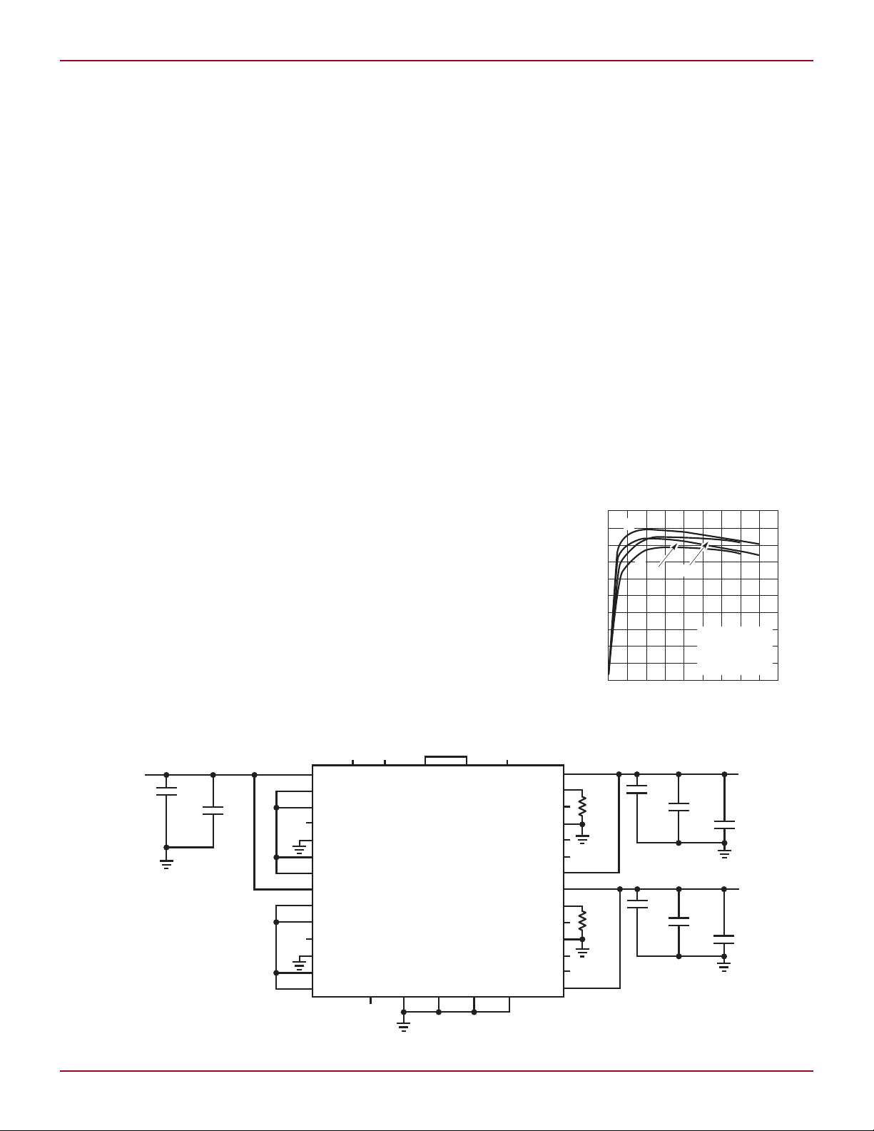
Simple and Efficient
The LTM4616 can be used as completely independent dual switching
regulators with different inputs and
outputs or paralleled to provide a
single output. Figure 1 shows a typical
design for a 5V common input and two
independent outputs, 1.8V and 1.2V.
Figure 2 shows the efficiency of the
circuit at both 5V and 3.3V inputs.
Few external components are needed
since the integrated output capacitors
can accommodate load steps to the full
8A. Each output voltage is set by a single
set resistor from FB1 (or FB2) to GND.
In parallel operation, the FB pins can
be tied together with a single resistor
for adjustable output voltage.
one another, making the top value
5k.
to CLKIN2 when operating from a
single input voltage. This minimizes
the input voltage ripple by running
the two regulators out of phase with
each other. If more than 16A output
current is required, then multiple
LTM4616 regulators can be configured
for multiphase operation with up to 12
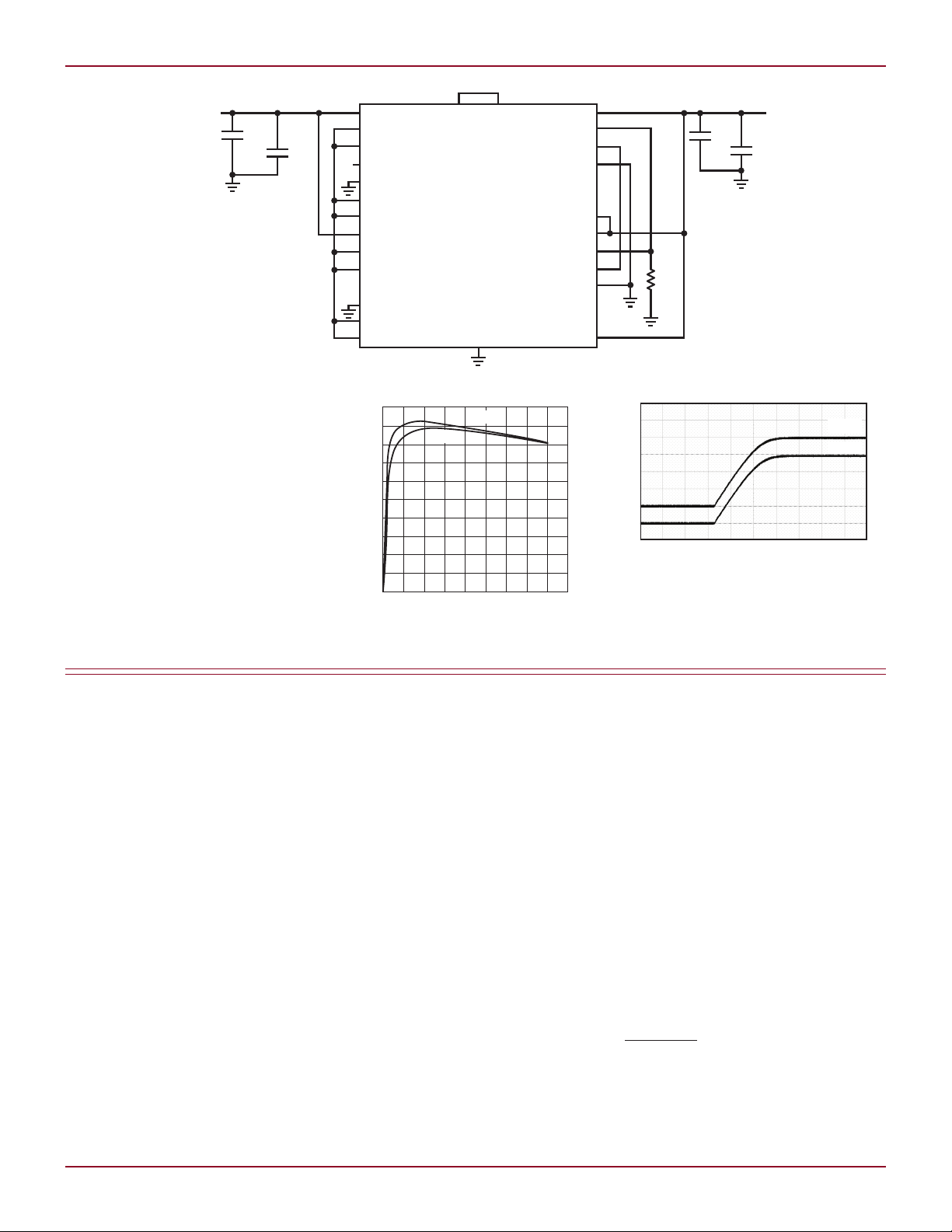
phases via the PHMODE pin. Figure
4 shows the expected efficiency of
the parallel system at 5V and 3.3V
inputs to 1.8V output. Note that the
Parallel Operation for
Increased Output Current
You can double the maximum output
current to 16A by running the two
outputs in parallel as shown in Figure
3. Note that the FB pins share a single
voltage-set feedback resistor that is
half the value of the feedback resistor
in the usual two output configuration.
This is because the internal 10k top
feedback resistors are in parallel with
It is preferred to connect CLKOUT1
Figure 2. LTM4616 efficiency: dual output
38
38
Figure 1. Dual output LTM4616 for a single 3.3V to 5V input, independent 1.8V and 1.2V outputs at 8A each
Linear Technology Magazine • September 2009
Page 2
two regulators drive equal output cur-
GND
CLKOUT1 CLKIN2
V
IN1
SV
IN1
RUN1
PLLLPF1
MODE1
PHMODE1
TRACK1
V
IN2
SV
IN2
RUN2
MODE2
PHMODE2
TRACK2
V
OUT1
FB1
ITH1
ITHM1
MGN1
V
OUT2
FB2
ITH2
ITHM2
MGN2
V
OUT
1.8V
16A MAX
C3
22µF
x2
C4
100µF
x4
V
IN
3.3V to 5V
C1
22µF
x2
C2
150µF
R
SET
2.49k
LTM4616
(15mm s 15mm s 2.8mm)
LOAD CURRENT (A)
0
EFFICIENCY (%)
50
40
30
80
70
60
18
20
10
0
2 4 6 8 10 12 14 16
100
90
3.3V
IN
5V
IN
0A
TIME (2ms/DIV)
OUTPUT CURRENT (2A/DIV)
0A
I
OUT1
I
OUT2
rent even during soft-start, as shown
in Figure 5.
Conclusion
Whether you require a single 16A high
current output or dual 8A outputs with
sequencing, the LTM4616 provides a
simple and efficient solution.
L
Figure 3. LTM4616 with 16A parallel operation
Figure 5. Balanced current sharing for even
heat dissipation [5VIN to 1.8V
DESIGN IDEAS L
at 16A]
OUT
LT3519, continued from page 36
high efficiency, small inductor and
capacitor size, and high PWM dimming
capability while avoiding frequencies
in the AM broadcast band. A small
inductor with about 750mA saturation current rating, a few ceramic
capacitors and several tiny resistors
are all that are needed to complete the
design. As shown in Figure 2, the tiny
PWM dimming MOSFET can be used
to provide over 1000:1 pwm dimming
at 120Hz using the integrated LT3519
PWM dimming architecture and an
extremely low leakage integrated
Schottky diode.
A 1000:1 dimming ratio at 120Hz
is exceptionally high for a 400kHz
switching regulator. It can be tempting to bump up the dimming ratio by
choosing a higher frequency driver,
since in general, higher switching
frequency corresponds to higher
PWM dimming ratios. In this case,
avoiding the AM band means jumping
Linear Technology Magazine • September 2009
Figure 4. Efficiency: single 1.8V output
to 2MHz, which in the end reduces
the maximum duty cycle and the
efficiency. The 400kHz switching
frequency of the LT3519 does what
2MHz converters cannot do: it provides
high duty cycle for operation down to
6VIN with 38V
and as high as 89%
LED
efficiency at 12VIN. If PWM dimming
is not needed, the MOSFET M1 can
be removed and the analog dimming
(CTRL) pin can be used to adjust the
regulated LED current below 100mA
for simple brightness control.
2.4W SEPIC LED Driver
When the LED string voltage is within
the input rail voltage range, a SEPIC
topology is called for. The SEPIC produces a high PWM dimming ratio and
also gives short-circuit protection. The
SEPIC in Figure 3 drives 16V LEDs at
150mA from a 4V to 24V input range.
Since the anode of the integrated catch
diode (ANODE) is made available at
a pin independent of the npn power
switch emitter (SW), the coupling
capacitor is easily inserted between
the two. The maximum voltage that
the SW pin sees is a little above the
input voltage plus the output voltage,
so the 45V 750mA integrated power
switch is a perfect match for these
specifications.
Conclusion
The 400kHz LT3519 is a 4W LED
driver that integrates a number of
required components, including a 45V,
750mA power switch, a low leakage
Schottky diode and compensation
components. It also features PWM
dimming, overvoltage protection and
OPENLED fault detection, making it a
small, simple, and efficient choice for
automotive, avionic, industrial and
other LED driver applications.
L
3939
 Loading...