

µModule Buck-Boost Regulators Offer a Simple and Effi cient
Solution for Wide Input and Output Voltage Range Applications
Design Note 438
Jian Yin and Eddie Beville
Introduction
An increasing number of applications require DC/DC
converters that produce an output that falls somewhere
within the input voltage range. The problem is that
conventional buck-boost converter topologies, such as
SEPIC or boost followed by buck, are complex, ineffi cient
and consume a relatively large board area. Linear Technology offers 4-switch-topology buck-boost regulators
that signifi cantly improve effi ciency and save space, but
a complete regulator design still requires a number of
external components and meticulous board layout decisions related to electrical and thermal considerations.
The next clear step to simplify the design is a modular
approach—a buck-boost regulator system in an IC form
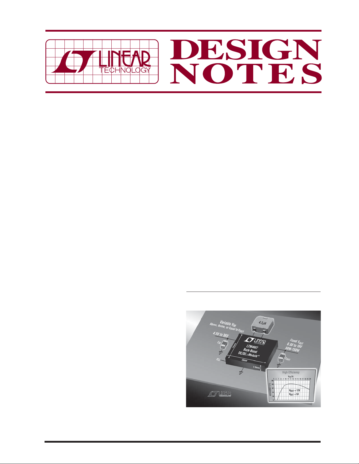
factor. The LTM4605 and LTM4607 μModule™ buck-boost
regulators take that approach. Each requires only one
external inductor and a single sensing resistor to produce
a compact, high perfor mance, high effi ciency buck-boost
regulator with exceptional thermal performance.
High Effi ciency
The LTM4605 and LTM4607 are high effi ciency switch
mode buck-boost power supply modules. The LTM4605
can operate over an input voltage range of 4.5V to 20V
and support any output voltage within the range of 0.8V
to 16V, set by a single resistor. As shown in Figure 1, the
LTM4607 support s 4.5V to 36V inputs and output s of 0.8V
to 16V. Both can prov ide 92% to 98% ef fi ciency over the
w i d e i n p u t r a n g e . T h i s h i g h e f fi c i e n c y d e s i g n d e l i v e r s u p t o
5A continuous current in boost mode (12A in buck mode).
Only the inductor, sensing resistor, and bulk input and
o u t p u t c a p a c i t o r s a r e n e e d e d t o fi n i s h t h e d e s i g n . F i g u r e 2
shows a typical LTM4605 application with an output
of 12V at 5A. An optional RC snubber is added here to
reduce switching noise for applications where radiated
EMI noise is a concern.
Low Profi le Solution
These power modules are offered in a space saving
and thermally enhanced 15mm × 15mm × 2.8mm LGA
package. This low profi le package can fi t the back side
of PC boards for many high density point-of-load applications. Their high switching frequency and current
mode architecture enable a fast transient response to
line and load changes without sacrifi cing stability. Both
can be frequency synchronized with an external clock to
reduce undesirabl e frequency harmonics. Fault prot ection
comes in the form of over voltage protection and foldback
current protection.
Smooth Transition and Circuit Simplicity
Both the LTM4605 and LTM4607 include the switching
controller, four power FETs, compensation circuitry and
support componen ts. The 4-switch topolog y provides high
effi ciency in all three modes of operation—buck, buckboost and boost— with a smooth transition bet ween each.
L, LT, LTC and LTM are registered trademarks and μModule is a trademark of Linear
Technology Corporation. All other trademarks are the property of their respective owners.
Figure 1. There is No Easier Way to Design a
High Effi ciency, High Power Density Buck-Boost
Regulator than with the LTM4605 or LTM4607
04/08/438
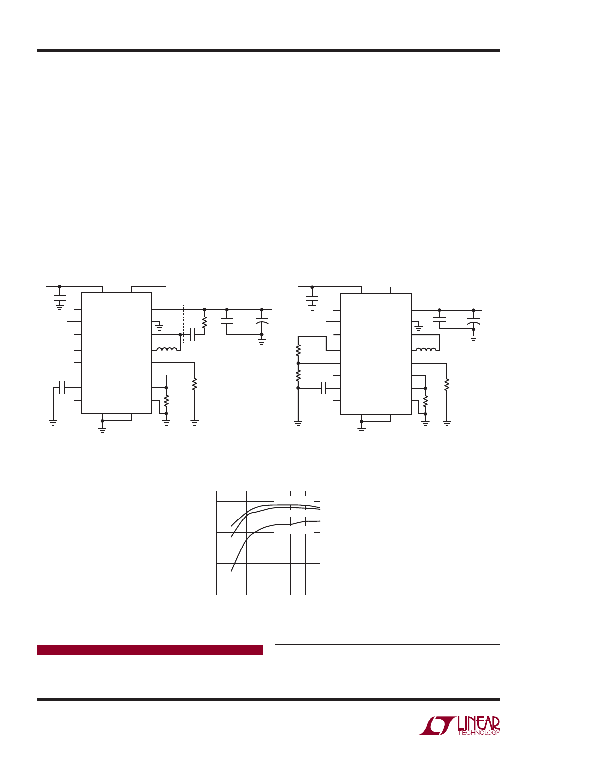
Figure 2 shows an actual buck-boost design with external components chosen to satisfy the boost mode’s 5A
maximum load current. For buck-only applications, the
maximum load current can be 12A at 12V
with the
OUT
same external components. For instance in a buck-only
confi guration, such as in Figure 3, the load current can
be increased up to 7A at 12V
for 168W capability.
OUT
This application can achieve better than 98% effi ciency
as shown in Figure 4.
Excellent Thermal Performance
The low profi le LGA package has a low thermal resistance
from junction to pin (4°C/ W), thus maintaining an acceptable junction temperature even w hen satisfying high power
requirements. Typically, operation in room temperature
ambient conditions requires no special heat sinking or
added airfl ow, but for warmer ambient environments or
high loads, simply add a heat sink to the top of the case
for 2-sided cooling and add air fl ow to signifi cantly lower
the thermal resistance from junction to ambient. The data
sheet provides more details about adding heat sinks and
air fl ow considerations.
Conclusion
There is no easier way to design an effi cient high-density
buck-boost converter than with the LTM4605 or LTM4607
μModule regulator. No design tricks are necessary to
achieve effi ciencies up to 98%—only one inductor, a
single sensing resistor and bulk capacitance are required
to complete a design. Low profi le LGA packages fi t on the
back side of PCBs and have good thermal performance,
enabling a 168W power output in an 8cm × 8.4cm 4-layer
PCB. These devices are ideal for automotive, telecom,
medical, motor drive and battery-powered applications.
5V TO 20V CLOCK SYNC
IN
ON/OFF
0.1μF
22μF
25V
C3
V
IN
PGOOD
RUN
COMP
INTV
CC
PLLFLTR
EXTV
CC
SS
STBYMD
SGND PGND
LTM4605
PLL
IN
V
OUT
FCB
SW1
SW2
V
R
SENSE
SENSE+
SENSE–
dn4eb F02
L1
4.7μH
FB
R2
2x12mΩ
Figure 2. Buck-Boost Converter Produces
12V
at 5A from a 5V to 20V Input Range
OUT
Figure 4. Effi ciency for the 24V
C1
R3
2200pF
2
FDA1254-4R7M
R1
7.15k
100
99
98
97
96
95
94
EFFICIENCY (%)
93
92
91
90
10μF x2
25V
*
*OPTIONAL SNUBBER
0
LOAD CURRENT (A)
24V TO 36V
IN
12V/5A
OUT
+
330μF
25V
28VIN TO 24V
32VIN TO 24V
36VIN TO 24V
426
ON/OFF
R3
4.64k
R4
1.21k
OUT
OUT
OUT
dn4eb F04
Converter in Figure 3
OUT
10μF x2
50V
C3
0.1μF
PGOOD
RUN
COMP
INTV
CC
PLLFLTR
EXTV
SS
STBYMD
PLL
V
IN
U1
LTM4607
CC
SGND PGND
IN
V
OUT
FCB
SW1
SW2
V
R
SENSE
SENSE+
SENSE–
dn4eb F03
10μF x2
50V
L1
8μH
FDA1254-8ROM
FB
R1
3.4k 1%
R2
13mΩ
Figure 3. Buck Converter Produces a
24V Output with 168W Capability
7315
24V/7A
+
OUT
270μF
50V
Data Sheet Download
www.linear.com/micromodule
Linear Technology Corporation
1630 McCarthy Blvd., Milpitas, CA 95035-7417
(408) 432-1900
●
FAX: (408) 434-0507 ● www.linear.com
For applications help,
call (408) 432-1900, Ext. 2593
dn438 LT/TP 0408 241K • PRINTED IN THE USA
© LINEAR TECHNOLOGY CORPORATION 2008
 Loading...