

L DESIGN FEATURES
5V
0.1µF
µC
0.1µF
LTC6930
V
+
GND
DIVA
DIVB
V
+
OUT
GND
IO2
IO1
IO3
CLK
DIVC
f
OSC
5V
0.1µF
µC
0.1µF
LTC6930
V
+
GND
DIVA
DIVB
V
+
OUT
GND
IO1
CLK
DIVC
f
OSC
Accurate Silicon Oscillator Reduces
Overall System Power Consumption
Introduction
Choosing a clock used to be simple:
grab an off-the-shelf fixed-frequency
super-accurate, low jitter quartz
crystal, or cobble together a rather
noisy, inaccurate RC oscillator using discrete components. Recently,
though, the number of clock choices
has expanded, making the decision
tougher, giving rise to a number of
important questions. Is crystal accuracy absolutely necessary? Are low
power consumption and reliability
important, suggesting an all silicon
solution? What about cheap ceramic
resonators—are they up to the task?
Each of th e s e s o l u t i o n s has
strengths and weaknesses. Power
consumption, accuracy, noise and
durability must all come into consideration when choosing a clock. The
LTC6930 is a self-contained, fully
integrated all silicon oscillator that
occupies a unique space within the
world of clock solutions, providing
a combination of accuracy and low
power features that is hard to beat.
The LTC6930, which requires no
additional external components, can
accurately provide fixed frequencies
between 32.768kHz and 8.192MHz
over a wide supply range of 1.7V–5.5V
(Table 1). It typically dissipates between 100µA and 500µA depending on
frequency and load, and is available
in both 8-lead 2mm × 3mm DFN and
standard MS8 packages.
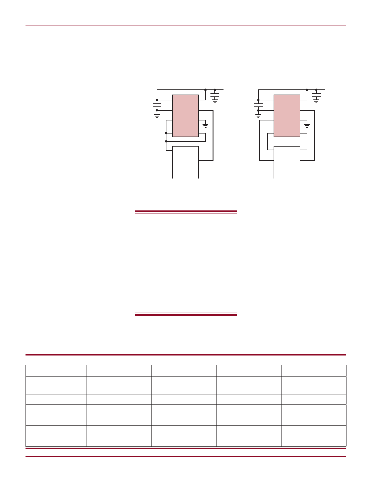
Figure 1. The LTC6930 clock configured as a 2speed clock, slow and fast clock speeds are set
via one I/O pin on a microprocessor
What is not immediately
obvious about the LTC6930
is that its low power
dissipation represents
only a small part of its
power-saving abilities. Its
accurate and fast start-up
and switching times save
substantially more system
power than the device
consumes by itself.
What is not immediately obvious
about the LTC6930 is that its low
power dissipation represents only a
small part of its power-saving abili-
by Albert Huntington
Figure 2. Fine control of the the LTC6930’s
frequency via three microprocessor I/O pins
ties. Its accurate and fast start-up
and switching times save substantially
more system power than the device
consumes by itself.
Smart Power Savings
Many electronic devices, especially
battery powered portable applications,
use low power sleep mode to conserve
power during times of low activity.
The depth and effectiveness of sleep
modes is limited by recovery requirements—namely, how fast must the
system come back up to full power. A
standard crystal oscillator can be a major contributor to recovery delays.
Crystal oscillators can take tens
of milliseconds to produce an accurate output when recovering from
DIV Pin Settings
[DIVC][DIVB][DIVA]
LTC6930-4.19
LTC6930-5.00
LTC6930-7.37
LTC6930-8.00
LTC6930-8.19
22
Table 1. LTC6930 available frequencies and settings
÷1 ÷2
000 001 010 011 100 101 110 111
4.194304MHz 2.097152MHz 1.048576MHz 524.288kHz 262.144kHz 131.072kHz 65.536kHz 32.768kHz
5.000MHz 2.500MHz 1.250MHz 625.0kHz 312.5kHz 156.25kHz 78.125kHz 39.0625kHz
7.3728MHz 3.6864MHz 1.8432MHz 921.6kHz 460.8kHz 230.4kHz 115.2kHz 57.6kHZ
8.000MHz 4.000MHz 2.000MHz 1000kHz 500.0kHz 250.0kHz 125.0kHz 62.5kHz
8.192MHz 4.096MHZ 2.048MHz 1024kHz 512.0kHz 256.0kHz 128.0kHz 64.0kHz
÷4 ÷8
÷16 ÷32
Linear Technology Magazine • September 2009
÷64 ÷128
DESIGN FEATURES L
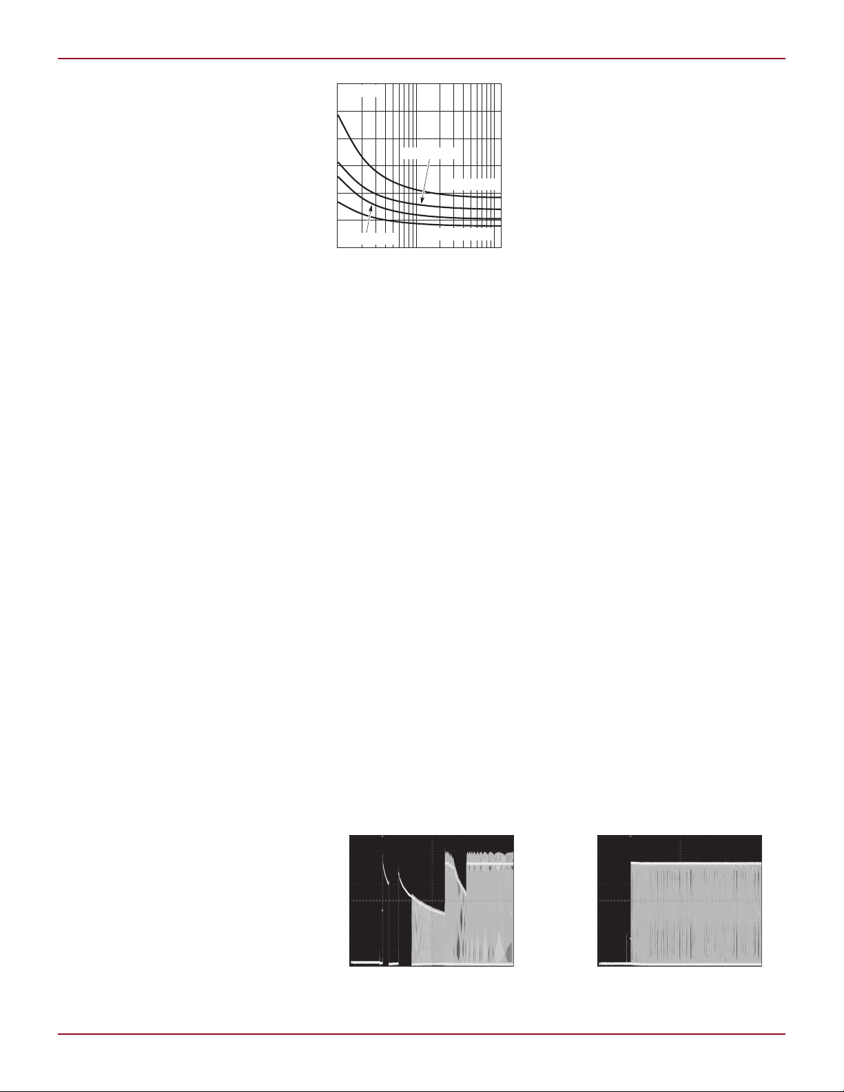
DIV SETTING (LOG)
1 10 100
SUPPLY CURRENT (µA)
600
8.192MHz, 3V
4.194MHz, 1.7V
500
400
300
200
100
0
6930 G04
4.194MHz, 3V
8.192MHz, 1.7V
TA = 25°C
V
OUT
500mV/DIV
200µs/DIV
OUT
500mV/DIV
200µs/DIV
a shutdown. The technique of using
two clocks, a fast clock for full power
operation and a slower sleep mode
clock, can degrade the accuracy and
recovery performance of the system—
where clock switching generates runt
pulses and slivers that can sabotage
sleep recovery times.
In contrast, the LTC6930 easily
and accurately transitions between
fast clock mode and a slower sleep
mode. The transition from one clock
frequency to another takes less than
a single clock cycle, and no runt
pulses or slivers are generated. The
LTC6930 also features a fast 100µs
start-up time and the first clock-out is
guaranteed to be clean. This makes it
possible for the designer to apply sleep
mode liberally, without worrying about
clock recovery, thus saving significant
overall system power.
Shifting the Clock Frequency
The output frequency of the LTC6930
is set by three DIV pins, which control
an internal clock divider. The factory
set master oscillator frequency may
be divided by a factor of up to 128,
and switching between these division
modes is accomplished within a single
clock period and without slivers or runt
pulses. All three pins may be tied together to enable a simple digital signal
from a microcontroller to shift the clock
down by a factor of 128 as shown in
Figure 1. This is enough to bring an
8MHz clock down to 64kHz.
The DIV pins can be addressed
in various combinations for smaller
frequency shifts or independently for
complex power modulating systems
where a microcontroller has fine
control over its own clock speed, as
shown in Figure 2.
Although there are some power
savings within the LTC6930 when the
output frequency is lowered (Figure 3),
far greater savings are realized in the
overall system. Power consumption
in CMOS devices such as microcontrollers is roughly proportional to their
operating clock speed. Slowing down
the clock by a factor of 128 during a
sleep condition can reduce the system
power by a factor of 100—very impor-
Linear Technology Magazine • September 2009
Figure 3. The LTC6930 supply current at
different divide ratios
tant in a system that spends significant
time in sleep mode.
Power Savings from
Fast Start-Up
Many systems are designed to sleep
most of the time and wake up briefly
on occasion to perform some task. If
a task requires particularly little time,
the total power dissipated for the task
may be dominated not by the awake
time, but by the time it takes for the
oscillator and associated sensory electronics to power up. The guaranteed
fast start-up time of the LTC6930
allows system designers to budget
minimal recovery time and thus save
power in start-up settling time.
Crystal oscillators often specify
start-up times of up to 20ms, if they
specify them at all, and the first clocks
out may be of low amplitude and otherwise out of spec. The designers task
is further complicated by the fact that
start-up time may vary randomly. See
Figures 4 and 5 to see how a crystal
oscillator start-up time compares quite
unfavorably to the LTC6930 start-up.
A system that needs to wake up occasionally for a millisecond to take
Figure 4. Typical crystal oscillator start-up
transients
a single measurement may end up
spending 100ms waiting for its clock
to come up without a clean signal
and then settle in order to take that
single measurement. The fast and
clean 100µs start-up of the LTC6930
allows the designer of such a system
to reduce wake time, and therefore
power dissipation, again by a factor
of around 100.
A Word on Accuracy
The big question when moving from
a quartz crystal to a silicon oscillator will always be one of accuracy. If
crystal oscillators do anything well,
it is provide a stable and accurate
frequency source, but accuracy is just
one concern out of many.
While each individual application is
different, Linear’s years of experience
with silicon oscillators allows us to
make some general recommendations
based on actual customer applications.
With an initial accuracy of better than
0.09% and a commercial grade accuracy over temperature of better than
0.45%, the LTC6930 does not compete
with crystal oscillators in all areas, but
does provide a clock accurate enough
for the most applications.
Of course, there are applications
that require either accuracy or jitter
characteristics out of the reach of the
LTC6930, such as clocking high speed
analog-to-digital converters such as
the LTC2242 series, clocking jitter
sensitive high speed serial communications systems such as Ethernet, and
long term timekeeping functions such
as a digital alarm clocks. Nevertheless,
silicon oscillators like the LTC6930
perform far better than crystal oscillators when power consumption is a
continued on page 35
Figure 5. Typical LTC6930 start-up
23

DESIGN IDEAS L
V
IN
5V/DIV
V
OUT
10V/DIV
V
SW
20V/DIV
10ms/DIV
V
IN
LTC3642
RUN
C
IN
1µF
HYST
SW
V
IN
12V
V
OUT
–24V
18mA
V
FB
SS
I
SET
GND
L1
100µH
R1
1.47M
R2
49.9k
CIN: TDK C3225X7R1H105KT
C
OUT
: MURATA GRM32DR71C106KA01
L1: TYCO/COEV DQ6530-101M
C
OUT
10µF
I
OUT
FAULT
V
OUT
10ms/DIV
I
OUT
FAULT
V
OUT
10ms/DIV
Figure 5. Generating a negative 24V output
voltage from a positive 12V input voltage
portable medical instruments and
certain automotive applications.
Positive-to-Negative Converter
The LTC3642 can produce a negative
output voltage from a positive input
voltage without the use of transformers
(see Figure 5). In this configuration,
the LTC3642 actually operates in an
inverting buck-boost mode. Its wide in-
LTC6930, continued from page 23
concern, and extreme accuracy is not
paramount. Such applications include
clocking microprocessors and microcontrollers, acting as a time base for
low speed serial communication protocols such as USB and RS232, digital
audio applications, clocking switching
power supplies and anywhere a general
purpose clock is needed.
Figure 6. The LTC3642’s wide input voltage swing makes it suitable
for generating a negative output from positive input voltage.
put voltage range, up to 45V, provides
sufficient headroom to generate any
negative voltage between –0.8V and
–40.5V. Figure 6 shows LTC3642 producing a –24V output from a 12V input
supply from start-up. The LTC3642
is inherently stable in this configuration with no external compensation
components required.
Conclusion
When comparing clock power dissipation it is important to consider not just
the dissipation of the oscillator itself,
but also how the oscillator’s features
and start-up times effect the dissipation of the entire system. Crystal
oscillators not only dissipate more current than other solutions, but can have
Conclusion
The LTC3642, LTC3631 and LTC3632
are a rugged DC/DC converters for use
in applications where a stable voltage
output must be produced from poorly
regulated high voltage rails. Their
compact size and high efficiency make
them easy to use in a wide variety of low
power applications, including mobile
and battery powered devices.
other start-up and control characteristics that lead to power waste. When
the LTC6930’s on-the-fly frequency
programmability and one-clock-cycle
settling time are considered, it is clear
that it conserves much more system
power than its dissipation specification
would indicate
L
L
LTC3529, continued from page 33
on a pin-selectable setting, the IC can
be configured to either periodically
attempt to power up (RST pin high,
Figure 4a), or remain shut down until power is cycled to the device (RST
pin low, Figure 4b). The waveform
indicating the fault condition is seen
at the Fault pin and is produced by
an internal open-drain device whose
input is pulled high in the event of
a fault. The Fault pin can either be
connected to a microprocessor or
drive an LED.
Conclusion
High conversion efficiency and the
ability to detect and handle output
shorts make the LTC3529 an ideal so-
Linear Technology Magazine • September 2009
4a. RST high: converter attempts power-up
every 15ms.
Figure 4. A fault detection mechanism powers down
the converter, providing robustness to output shorts
lution for either peer-to-peer portable
applications or point-of-load board
power with robust fault handling.
The 1.5MHz switching frequency
4b. RST low: converter remains shut down
until power is cycled.
and highly integrated design of the
LTC3529 yield compact solutions with
minimal design effort.
L
3535
 Loading...