

advertisement
Dual Current-Sense Amplifi ers Simplify H-Bridge Load Monitoring
Design Note 407
Jon Munson
Introduction
The H-bridge power-transistor topology is increasingly
popular as a means of driving motors and other loads bidirectionally from a single supply potential. In most cases
there is great benefi t in monitoring the current delivered
to the load and utilizing this information in real-time to
provide operational feedback to a control system. In most
new designs, pulse-width-modulation (PWM) techniques
are used to provide highly ef fi cient variable power-delivery,
but this places extremely fast voltage transitions at both
terminals of the load and therefore complicates the instrumentation problem. N ew high side current sense amplifi ers
from Linear Technology can simplify this problem.
Measuring Load Current in the H-Bridge
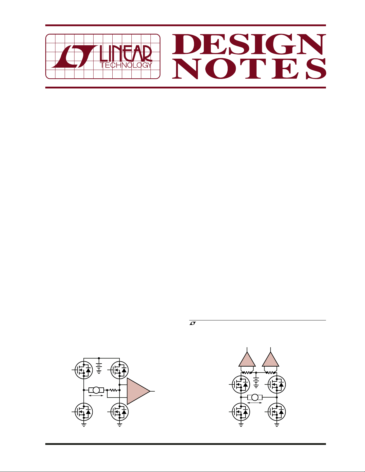
The classical approach to load monitoring is to place a
small value sense-resistance in series with the load that
can develop a measurable voltage drop representing the
load current (see Figure 1). The diffi culty here is that with
PWM activity, the common mode voltage at the sense
resistor has nasty voltage transitions that can corrupt the
sense amplifi er opera tion with high frequency hash. While
this hash can be fi ltered to recover useful low frequency
information, the ability to provide fast fault protection
is then lost. Additionally, this “fl ying” sense resistor
confi guration is unable to monitor switch shoot-through
current, leaving many important fault modes undetected
or unmanaged (failed switch function, for example).
A far more practical method is to monitor the supply
current fed to each half-bridge as shown in Figure 2.
This scheme provides several benefi ts that simplify and
improve the circuit performance. The main improvement
comes from having the sense resistors at a relatively
constant common mode voltage (i.e., the power supply
voltage) so that fi delity of the PWM current waveform
can be preserved. Additionally, by monitoring each halfbridge individually at the supply side, both failed power
device operation and load shorts to ground are readily
detected and manageable.
By using PWM logic that generates “sign-magnitude”
control, one of the half-bridges is in a 100% pull high
c o n d i t i o n ( d e p e n d i n g o n t h e d i r e c t i o n o r p o l a r i t y o f d r i v e ) .
The load current equals the current delivered through the
100% (fully on) switch, unaffected by the duty cycle of
the PWM activity on the other half-bridge. This permits
s i m p l e r e c o n s t r u c t i o n o f t h e l o a d c u r r e n t w a v e f o r m u s i n g
suitable high side sense amplifi cation techniques.
The Simple Solution
The LTC6103 and LTC6104 dual high side sense amplifi ers
are ideal for per forming the H-bridge monitoring func tion.
Both parts include two current sense input channels and
, LT, LTC and LTM are registered trademarks of Linear Technology Corporation.
All other trademarks are the property of their respective owners.
+
+
R
S
I
M
DN407 F01
DIFF
AMP
–
+
+
DN407 F02
–
R
S
–
R
S
+
I
M
Figure 1. Classical Load Sensing Problematic with PWM Figure 2. PWM-Compatible H-Bridge Load Sensing
01/07/407
furnish either two unidirectional outputs (LTC6103) or a
single bidirectional output (LTC6104). Since each current
sense channel operates in a unidirectional fashion, only
the current from the fully on half-bridge is monitored.
Since the current pulses in the other half-bridge are in
the opposite direction, that amplifi er channel remains in
a cutoff condition and does not impact the reading. This
means that the output signals only refl ect the fully-on
half-bridge current, which is identical to the controlled
load current.
W i t h t h ei r fa s t (m i c r os e c on d le v el ) re s po n se t im e s, t he s e
parts also offer overload sensing, thereby providing the
ability to signal power device protection circuits in the
event of fault conditions. Both parts are furnished in tiny
MSOP-8 packages for compact layouts and can operate
with up to 60V power supply potentials. With their 70V
transient capability, the need for additional surge suppression components is eliminated in harsh automotive
applications.
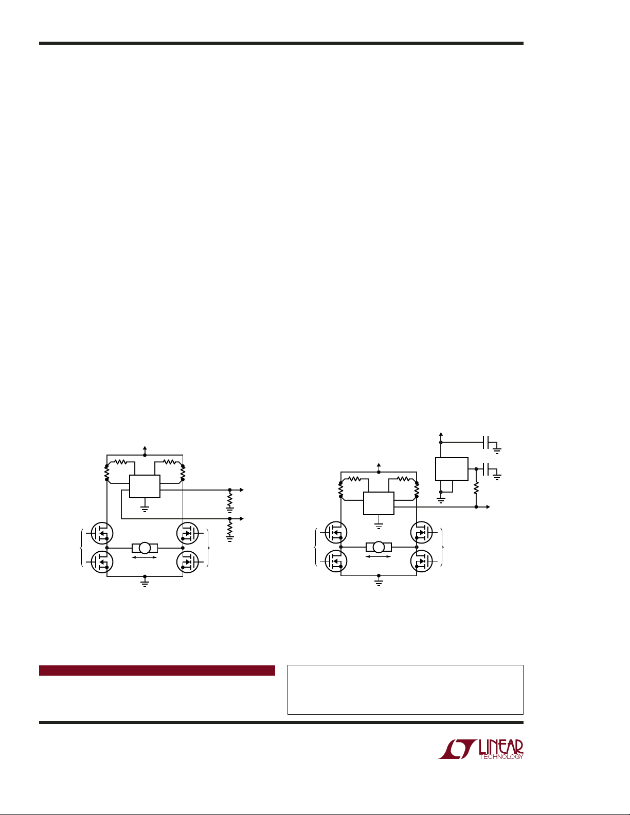
The dual outputs of the LTC6103 can be used individually
to provide overload detection, and/or may be taken as
a differential pair to provide a bidirectional signal to an
analog-to-digital converter (ADC) for example. Figure 3
shows a typical circuit for a generic H-bridge application.
The power devices may be complementary MOSFETs,
pure N-MOSFETs, or other switching devices. When the
bridge drives the load (a motor assumed in the example
shown), one of the LTC6103 outputs rises above ground,
while the other remains pulled down to ground, thereby
forming an accurate bidirectional differential output with
a common mode voltage that never falls below ground.
The selection of output resistance (4.99k in the example)
can be scaled to satisfy the source-impedance requirement of any ADC.
As an alternative, the output structure of the LTC6104
provides a single bidirectional signal. The output connect io n c an ei t he r s ou r ce or si nk cu rr en t t o a lo ad re si st a nc e,
depending on which input channel is sensing current fl ow.
A negative-going output swing remains linear as long
–
as Pin 4 (V
) is lower than the lowest expected output
level by at least 0.5V. This condition is met if the load
resistance is returned to a suitable reference voltage while
Pin 4 is grounded (as shown in the Figure 4 example).
The output resistance could also be returned directly to
ground to form a true bipolar output if Pin 4 is tied to a
suitable negative supply, such as –3V.
Conclusion
Designing a load current monitor for an H-bridge power
driver is not diffi cult if you have the right amplifi er. The
LTC6103 and LTC6104 fi t the bill. They include dual
sense inputs and a choice of two different output confi gurations—features that reduce complexity and printed
circuit area.
V
BATTERY
(4V TO 60V)
10m10m
DIFFERENTIAL
OUTPUT =
±2.5V FS (±10A FS)
4.99k
4.99k
PWM*
PWM*
LTC6103
4
I
M
200Ω
6
DN407 F03
200Ω
7
85
12
*USE "SIGN-MAGNITUDE" PWM FOR ACCURATE
LOAD CURRENT CONTROL AND MEASUREMENT
Figure 3. LTC6103 Provides Bidirectional H-Bridge
Monitoring with ADC-Friendly Differential Output
Data Sheet Download
www.linear.com
3V TO 18V
V
BATTERY
(6V TO 60V)
249Ω
+
–
PWM*
7
85
*USE "SIGN-MAGNITUDE" PWM FOR ACCURATE
LOAD CURRENT CONTROL AND MEASUREMENT
LTC6104
4
I
M
249Ω
6
2
DN407 F04
10m10m
4
LT1790-2.5
2
1
PWM*
0.1µF
1µF
6
4.99k
V
= 2.5V ±2V (±10A FS)
V
O
O
Figure 4. LTC6104 Provides Bidirectional H-Bridge
Monitoring with Single-Ended Output
For applications help,
call (408) 432-1900, Ext. 2020
Linear Technology Corporation
1630 McCarthy Blvd., Milpitas, CA 95035-7417
(408) 432-1900
●
FAX: (408) 434-0507 ● www.linear.com
dn407f LT/TP 0107 409K • PRINTED IN THE USA
© LINEAR TECHNOLOGY CORPORATION 2006
 Loading...