

advertisement
Ideal Diode Controller Eliminates Energy Wasting Diodes in Power
OR-ing Applications –
Design Note 386
David Laude
Introduction
Many modern electronic devices need a means to automatically switch between power sources when prompted
by the insertion or removal of any source. The LTC®4412
simplifies PowerPath
viding a low loss, near ideal diode controller function. Any
circuit that could otherwise use a diode OR to switch
between power sources can benefit from the LTC4412.
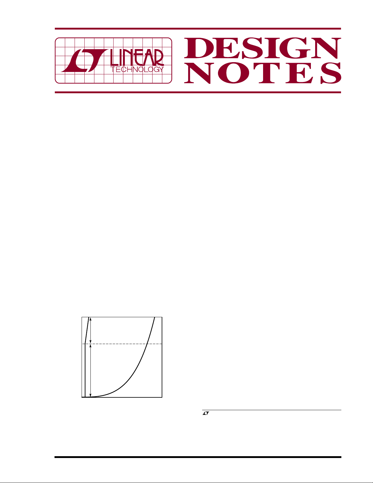
The forward voltage drop of an LTC4412 ideal diode is far
less than that of a conventional diode, and the reverse
current leakage can be smaller for the ideal diode as well
(see Figure 1). The tiny forward voltage drop reduces
power losses and self-heating, resulting in extended
battery life. Features include:
• Voltage drop across the controlled external MOSFET of
only 20mV (typical)
• Low component count helps keep overall system cost
low
• 6-pin ThinSOT
solution
1
TM
management and control by pro-
TM
package permits a compact design
CONSTANT
R
ON
(VGS LIMITED)
LTC4412
• Wide supply operating range of 2.5V to 28V (36V
absolute maximum)
• Protection of MOSFET from excessive gate-to-source
voltage with VGS limiter
• Low quiescent current of 11µA with a 3.6V supply,
independent of the load current
• A status pin that can be used to enable an auxiliary
MOSFET power switch or to indicate to a microcontroller
that an auxiliary supply, such as a wall adapter, is
present
• A control input pin for external control, such as from a
microcontroller
Applications include anything that takes power from two
or more inputs:
• Cellular phones
• Portable computers
• PDAs
• MP3 players and electronic video and still cameras
• USB peripherals
• Wire-ORed multipowered equipment
• Uninterruptible power supplies for alarm and emergency systems
03/06/396
0
0.02
CONSTANT
VOLTAGE
(VGS VARIABLE)
FORWARD VOLTAGE (V)
SCHOTTKY
DIODE
0.5
DN386 F01
CURRENT (A)
Figure 1. LTC4412 Ideal Diode Controller vs
Schottky Diode Characteristics
• Systems with standby capabilities
• Systems that use load sharing between two or more
batteries
• Multibattery charging from a single charger
• Logic controlled power switches
, LTC and LT are registered trademarks of Linear Technology Corporation.
PowerPath and ThinSOT are trademarks of Linear Technology Corporation.
Automatic Power Switching Between
Two Power Sources
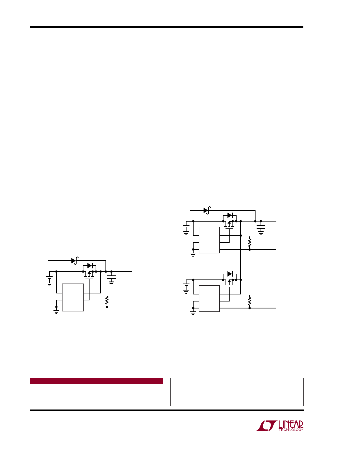
Figure 2 illustrates an application circuit for the automatic
switchover of load between two power sources, in this
example a wall adapter and a battery. While the wall
adapter is absent, the LTC4412 controls the gate of Q1 to
regulate the voltage drop across the MOSFET to 20mV,
thus wasting negligible battery power. The STAT pin is an
open circuit while the battery provides power. When a
wall adapter or other supply connected to the auxiliary
input is applied, the SENSE pin voltage rises. As the
SENSE pin voltage rises above V
– 20mV, the LTC4412
IN
pulls the GATE voltage up to turn off the P-channel
MOSFET. When the voltage on SENSE exceeds V
IN
+
20mV, the STAT pin sinks 10µA of current to indicate that
an AC wall adapter is present. The system is now in the
reverse turn-off mode, where power to the load is delivered through the external diode and no current is drawn
from the battery. The external diode is used to protect the
battery against some auxiliary input faults such as a short
to ground. Note that the external MOSFET is wired so that
the drain to source diode will reverse bias and not deliver
current to the battery when a wall adapter input is applied.
Load Sharing
Figure 3 shows a dual battery load sharing application
with automatic switchover of power between the batteries
and a wall adapter. In this example, the battery with the
WALL
ADAPTER
INPUT
BATTERY
CELL(S)
1N5819
*
TO LOAD
C
Q1
LTC4412
1
V
IN
2
GND
3
CTL
*PARASITIC DRAIN-SOURCE DIODE OF MOSFET
Q1: FAIRCHILD SEMICONDUCTOR FDN306P (408) 822-2126
SENSE
GATE
STAT
6
5
4
OUT
V
CC
470k
STATUS OUTPUT LOW
WHEN WALL ADAPTER IS
DN386 F02
SUPPLYING LOAD CURRENT
higher voltage supplies all of the power until it has
discharged to the voltage of the other battery. Once both
batteries have the same voltage, they share the load with
the battery with the higher capacity providing proportionally higher current to the load. In this way, the batteries
discharge at a relatively equal rate, maximizing battery run
time.
When a wall adapter input is applied, both MOSFETs turn
off and no load current is drawn from the batteries. The
LTC4412’s STAT pins provide information as to which
input is supplying the load current. The ganging of the
LTC4412s can be applied to as many power inputs as are
needed.
Conclusion
The LTC4412 provides a simple means to implement a low
loss ideal diode controller that extends battery life and
reduces self heating. The low external parts count results
in low implementation cost and with its ThinSOT 6-pin
package, a compact design as well. Its versatility is useful
in a variety of applications (see the LTC4412 data sheet for
additional applications).
WALL
ADAPTER
INPUT
BAT1
BAT2
1N5819
*
Q1
LTC4412
1
V
IN
2
GND
3
CTL
LTC4412
1
V
IN
2
GND
3
CTL
*PARASITIC DRAIN-SOURCE DIODE OF MOSFET
Q1, Q2: SILICONIX Si4953DY (800) 554-5565
SENSE
GATE
STAT
SENSE
GATE
STAT
6
5
4
Q2
*
6
5
4
V
CC
470k
WHEN BOTH STATUS LINES ARE
HIGH, THEN BOTH BATTERIES ARE
SUPPLYING LOAD CURRENTS. WHEN
BOTH STATUS LINES ARE LOW, THEN
WALL ADAPTER IS PRESENT AND
SUPPLYING FULL LOAD CURRENT
V
CC
470k
C
DN386 F03
TO LOAD
OUT
STATUS IS HIGH
WHEN BAT1 IS
SUPPLYING
LOAD CURRENT
STATUS IS HIGH
WHEN BAT2 IS
SUPPLYING
LOAD CURRENT
Figure 2. Automatic Power Switching Between
a Battery and a Wall Adapter
Data Sheet Download
www.linear.com
Linear Technology Corporation
1630 McCarthy Blvd., Milpitas, CA 95035-7417
(408) 432-1900 ● FAX: (408) 434-0507 ● www.linear.com
Figure 3. Dual Battery Load Sharing with Automatic
Switchover of Power from Batteries to Wall Adapter
For applications help,
call (408) 432-1900, Ext. 2593
dn386f LT/TP 0306 409K • PRINTED IN THE USA
© LINEAR TECHNOLOGY CORPORATION 2006
 Loading...