

advertisement
High Power PoE PD Interface with Integrated Flyback Controller
Design Note 425
Dilian Reyes
Introduction
To this day, Power over Ethernet (PoE) continues to gain
popularity in today’s networking world. The 12.95W
delivered to the Powered Device (PD) input supplied by
the Power Sourcing Equipment (PSE) is a universal supply. Each PD provides its own DC/DC conversion from a
nominal 48V supply, thus eliminating the need for a correct voltage wall adapter. However, higher power devices
can not take advantage of standard PoE because of its
power limitations, and must rely on a large wall adapter
as their primary supply. The new LTC4268-1 breaks this
power barrier by allowing for power of up to 35W for such
power-hungry 2-pair PoE applications. The LTC4268-1
provides a complete solution by integrating a high power
PD interface control with an isolated fl yback controller.
PD Interface Controller
The PD interface controller provides the same 25k signature detection resistance defi ned in the standard PoE.
An extended optional class can be read by a customized
L2
4.7μH
+
C1A
PoE+
PoE–
AUX+
AUX–
FMMT723
R14
4.7k
R18
100k
C8
0.1μF
100V
V
12μF
100V
PORTN
V
PORTN
PWRGD
D12
B2100
C1B
2.2μF
100V
C18
+
22μF
16V
100k
PWRGD UVLO PGV
LTC4268-1
t
PGDLYV
NEGVNEGVNEG
R
PGDLY
15k
D1
SMAJ58A
Q5
V
PORTP
SHDN
R
CLASS
V
R21
20k
PORTN
R
CLASS
I
ON
LIM_EN
R
100k
SYNC
tON
C19
0.1μF
CC
R
CMP
R9
20k
1/4W
ENDLY OSC SFST
R
CMP
2.1k
PSE that looks for such a class. Once a PSE detects
and classifi es the PD, it fully powers on the device. The
LTC4268-1 provides a low inrush current limit, allowing load capacitance to ramp up to the line voltage in
a controlled manner without interference from the PSE
current limit. Af ter the load capacitance is charged up, the
LTC4268-1 switches to the high input current limit and
provides a power good signal to its switching regulator
indicating that it can start its operation. During this time,
the LTC4268-1 remains in its high current limit state allowing for up to 35W delivered to the load.
Synchronous Flyback Controller
Once power is switched over to the synchronous fl yback
controller, the LTC4268-1 regulates the output voltages
by sensing the average of all the output voltages via a
transformer winding during the fl yback time. This allows for tight output regulation without the use of an
, LT, LTC and LTM are registered trademarks of Linear Technology Corporation.
All other trademarks are the property of their respective owners.
R3
10Ω
1/4W
R8
10Ω
1/4W
R13
B0540W
R15
47Ω
C24
1μF
L1
0.33μH
+
+
C5
47μF
L3
0.33μH
C21
47μF
×2
+
+
+
C6
100μF
C10
22μF
×2
C22
100μF
R
150k
ENDLY
D11
BAS21
R10
91Ω
C
33pF
OSC
0.033
T1
PA1558NL
•
•
Q1
Si4470EY
SENSE
C26
PA0184
R17
330Ω
C27
0.1μF
T2
•
•
C23
4700pF
250VAC
•
Si4488DY
•
Si4362DY
C28
2200pF
•
Q2
Q4
R2
10Ω
C7
1000pF
R13
100V
29.4k
1%
R20
301k
1%
Q3
FB
SENSE
SENSE
C
GND
CMP
C
CMP
0.1μF
μF
C
SFST
Si4488DY
+
R
0.015Ω
1/8W
–
1%
SG
V
CMP
C33
3300pF
R27
10k
680pF
1500pF
C11
220pF
Q7
FMMT718Q6FMMT618
R22
15Ω
R28
D14
10k
BAT54
dn425 F01
C4
5V
2.4A
11.8V
0.4A
3.3V
4A
09/07/425
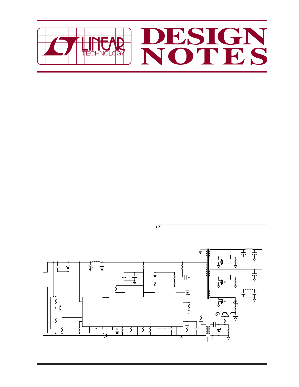
Figure 1. High Effi ciency, Triple Output, High Power PD
optoisolator, providing improved dynamic response
and reliability. Synchronous rectifi cation increases the
conversion effi ciency and cross-regulation effectiveness
above a conventional fl yback topology. No external driver
ICs or delay circuits are needed to achieve synchronous
rectifi cation; a single resistor is all that is needed to
program the synchronous rectifi er’s timing.
High Effi ciency, Triple Output, High Power PD
Figure 1 shows a design using the LTC4268-1 in a high
power, triple output PD. A high power PSE connects
through an Ethernet cable to the RJ45 connector. PSE
detection and power is passed through the data pairs’
high power Ethernet transformer or directly to the spare
pairs in this 2-pair 10/100BaseT PoE system. The PSE
power is then controlled by the LTC4268-1 PD interface
and forwarded on to its switching regulator. An auxiliary
supply option can also be connected to bypass and disable the PD interface which gives the auxiliary priority in
power supply over PoE. Power conversion is then from
the auxiliary supply down to the output voltages.
The small supply of the LTC4268-1 utilizes an isolated
fl yback topology with synchronous rectifi cation that
requires no optoisolator, lowering the parts count. This
circuit gives effi ciencies at full load of 83% when powered from a PSE and over 85% power sourced from an
auxiliary supply.
PSE and Auxiliary Supplies
Standard PSEs are capable of providing as low as 15.4W
at the port output. This would not be suffi cient power for
a high power PD operating at full load. Here, a customized
PSE capable of delivering higher power must be used,
or a PSE controller designed for high power such as an
LTC4263-1 single port PSE controller. In cases where a
high power PSE is not available, an auxiliary supply can
be used.
2-Pair vs 4-Pair PD
2-pair power is used today in IEEE 802.3af systems. One
pair of conductors is used to deliver the current and a
second pair is used for the return while two conductor
pairs are not power ed. This architecture of fers the simplest
implementation method but suffers from higher cable
loss than an equivalent 4-pair system.
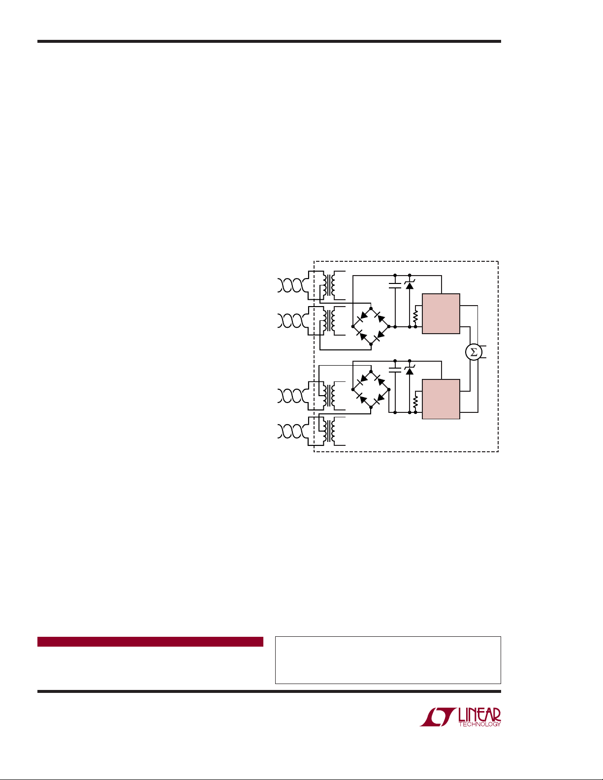
4-pair power delivers current to the PD via t wo conductor
pairs in parallel allowing for an even higher level of power.
This lowers the cable resistance but raises the issue of
current balanc e between each conductor p air. Dif ferences
in resistance of the transformer, cable and connectors
along with differences in diode bridge forward voltage
in the PD can cause an imbalance in the currents fl owing
through each pair. Using two independent LTC4268-1s
(Figure 2) allows for interfacing and power from two
independent PSEs, and independent DC/DC converters
resolve the current imbalance.
RJ45
CAT5
1
Rx1
2
3
Tx1
6
4
Rx2
5
7
Tx2
8
0.1μF
DF1501S
0.1μF
DF1501S
Figure 2. 4-Pair, High Power PD Diagram
PD
SMAJ58A
SMAJ58A
LTC4268-1
TYP APP
LTC4268-1
TYP APP
+
–
+
V
OUT
–
+
–
dn4DR F02
Conclusion
The LTC4268-1 is a highly integrated solution for the next
generation of PD products. It offers PoE PD functionality with control for effi cient high power delivery to the
output load.
Data Sheet Download
www.linear.com
Linear Technology Corporation
1630 McCarthy Blvd., Milpitas, CA 95035-7417
(408) 432-1900
●
FAX: (408) 434-0507 ● www.linear.com
For applications help,
call (408) 432-1900, Ext. 2360
dn425f LT/TP 0907 451K • PRINTED IN THE USA
© LINEAR TECHNOLOGY CORPORATION 2007
 Loading...