

advertisement
Simple Battery Circuit Extends Power over Ethernet (PoE)
Peak Current –
Design Note 361
Mark Gurries
Introduction
Power over Ethernet (PoE) is a new development that
allows for the delivery of power to Ethernet-based devices
via standard Ethernet CAT5 cable, precluding the need for
wall adapters or other external power sources. The PoE
specification defines a hardware detection protocol where
Power Sourcing Equipment (PSE) is able to identify PoE
Powered Devices (PDs), thus allowing full backwards
compatibility with non-PoE-aware (legacy) Ethernet
L1
3.3µH
C2
1µF
1N5237B
13
12
1,8,9,16
1-CELL 4.2V
Li-Ion
+
R18
53.6k
100V X7R
D5
8.2V
C4
4.7µF
10V X5R
4
P
VCC
6
NC
V
PORTP
5
R
CLASS
SIGDISA
7
V
PORTIN
PGND
R19
105k
1%
R2
220k
LTC4267
C10
0.1µF
Q2
MMBTA42
NGATE
SENSE
ITH/RUN
PWRGD
P
C11
10µF
6.3V
FROM
DATA
PAIR
FROM
SPARE
PAIR
5V POE
34.8k
ETHERNET
R15
R16
10k
1%
AC1 BR2
AC2 HDO1
AC1 BR1
AC2 HDO1
D9
UPS340
C1
0.1µF
100V
X7R
+
C5
4.7µF
100V
LTC4055
5
WALL
6
SHDN
7
SUSP
8
HPWR
13
ACPR
14
CHRG
TIMER
CLPROG
PROG
TO HOST
OUT
BAT
GND
3
2
12
9
11
10
D2
SMAJ58A
devices. The PoE specification also sets an upper limit on
the power that can be drawn by a PD. The problem is: what
happens when a PD must draw more power than allowed
by the PoE standard? Examples may be the spin up of a
disk drive or a period of sustained transmission of data
from an RF transmitter. If the
, LTC and LT are registered trademarks of Linear Technology Corporation.
PowerPath is a trademark of Linear Technology Corporation.
All other trademarks are the property of their respective owners.
3
14
15
V
FB
2
11
10
OUT
TO DC/DC
CONVERTERS
C3
68pF
200V
R3
220k
D3
BAS516
R5
4.7k
2N7002
R1
10k
R8
100kR96.8k
R6
510Ω
Si3440DV
Q3
D4
BAS516
P
VCC
R7
100Ω 1/8W
Q1
PA1134
4
3
2
1
R4
0.125Ω
1% 1/4W
6.3V
D7
BAS516
PS2911
5
4
C8 2.2nF
250V AC YCAP
C12
1µF
T1
aver
8
6
7
5
age
power load of these
C6
R10
470pF
10Ω
D1
SMB540
C9 220µF
6.3V OS-CON
+
C14 100µF
6.3V X5R ×2
R21
470Ω
R11
C13
1k
33nF
R13
100k
1%
ZRL431
R12
47k
C7
27nF
R14
D8
33.2k
DN361 F01
1
2
5V POE
5V
1.8A
04/05/361
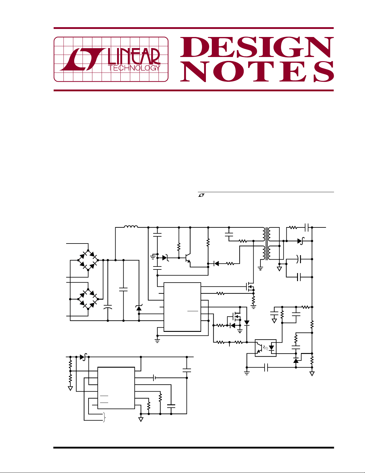
Figure 1. Simple Battery Charger/PowerPathTM Controller (LTC4055) Augments PoE Regulator’s
(LTC4267) Peak Output Power to Overcome PoE Power Constraints

applications is less than the available PoE power, one
solution is to store power in the PD when power consumption is low and then tap the reserve to augment PoE
power when needed. For many applications, a rechargeable battery fits the bill.
path is the battery discharge path. When the 5V PoE power
goes away or drops out of regulation, the LTC4055
automatically switches the battery power over to the OUT
pin using its internal ideal diode circuit. There is no delay
in the switchover, so power is never lost.
Of course, one can’t just throw a battery and a battery
charger into the mix. The power path must be able to
change seamlessly, on the fly, from PoE-powers-deviceand-charges-battery, to PoE-and-battery-power-device,
to battery-powers-device. Figure 1 shows a complete and
compact solution.
The PoE Circuit
By default, power over the Ethernet is
not
available. The
standard calls for a protocol to be implemented that
allows the Ethernet hub to identify the device needing
power. The LTC
®
4267 simplifies the design of PDs by
providing wholesale implementation of the protocol and
power management functions.
PoE power comes in the form of –48V at 350mA. If the
PoE current is allowed to exceed 400mA, the standard
calls for the PSE to break the circuit. This is a problem for
devices that occasionally need a little more juice than PoE
will offer. Another problem is that –48V does not easily
convert to commonly used positive voltage supply rails.
Designers are forced to provide DC isolation along with
the inverted down conversion to a more usable voltage. To
meet these requirements, the LTC4267 used in Figure 1’s
circuit implements an input current limited DC input
isolated flyback converter, providing a user-settable regulated low voltage.
The LTC4267 circuit in Figure 1 supplies 5V at 1.8A. 5V is
a popular supply voltage to run logic, interface with other
devices such as USB, and of primary concern in this
application, to charge a single Li-Ion cell to its target
termination voltage of 4.2V.
PowerPath and Charger Circuit
In Figure 1, the LTC4055 provides triple PowerPath control and Li-Ion battery charging. One path is created by
connecting an external Schottky diode to the LTC4055’s
OUT pin and the built-in wall adapter detection circuits. In
this case, the “wall adapter” power comes from the
LTC4267 5V power supply called 5V PoE. The second path
is for USB power, not used in this application. The third
When 5V PoE power is restored, the battery is disconnected from the load and charging is permitted. The
LTC4055 charge current is adjustable and in Figure 1, the
circuit is limited to 900mA which is drawn from the OUT
pin. That leaves 900mA to run the system while charging.
Powered devices connected to the OUT pin must be
compatible with the Li-Ion voltage range. The ACPR pin of
the LTC4055 can be used to indicate which power source
is providing power, allowing the PD to configure itself
accordingly.
High Transient Load or Continuous Current
Load Operation
When the power limit of the 5V PoE supply is reached, the
voltage drops and the battery charger shuts down to
relieve the PSE of the charge current load. If the voltage
continues to collapse, the battery automatically is placed
into parallel operation with the 5V PoE power supply, thus
increasing the available peak load current. The LTC4055
ACPR signal is active high during the overload. Battery
charging automatically resumes once the overload goes
away and the 5V PoE voltage has risen enough to show
recovery.
Optimization Options
If sustained currents approaching 1.8A are expected from
the 5V PoE and there are thermal management issues
related to the diode’s heat dissipation, the diode D9 can be
replaced with the LTC4411 ideal diode for more efficient
operation. Recommended DC/DC converters to generate
logic supplies in this application include the LTC3443
buck-boost and/or the LTC3407-2 dual buck regulators.
Conclusion
The highly integrated LTC4267 and LTC4055 simplify the
design of compact, simple and complete battery-based
power systems that run from Ethernet power. More
importantly, seamless PowerPath control enables circuits that can use a battery to augment Ethernet power
when an application momentarily demands more than the
PoE standard allows.
Data Sheet Download
http://www.linear.com
Linear Technology Corporation
1630 McCarthy Blvd., Milpitas, CA 95035-7417
(408) 432-1900 ● FAX: (408) 434-0507 ● www.linear.com
For applications help,
call (408) 432-1900, Ext. 2364
dn361f LT/TP 0405 305K • PRINTED IN THE USA
© LINEAR TECHNOLOGY CORPORATION 2005
 Loading...