

DETECTION V1
ON
UVLO
UVLO UVLOON
T = R
LOAD
C1
TRACKS
V
IN
DETECTION V2
TIME
PD CURRENT
50
40
30
GND (V)
20
10
40mA
50
40
30
20
10
TIME
GND – V
OUT
(V)
–10
TIME
–20
–30
GND – T2PSE (V)
–40
–50
dV
dt
INRUSH
C1
=
INRUSH = 100mA R
CLASS
= 30.9Ω
I
LOAD
=
V
IN
R
LOAD
GND
PSE
I
IN
R
LOAD
R
CLASS
V
OUT
C1
GND
R
CLASS
T2PSE
LTC4265
V
OUT
V
IN
1st CLASS
1st MARK 2nd MARK
DETECTION V1
DETECTION V2
1st MARK 2nd MARK
2nd CLASS
1st CLASS
2nd CLASS
LOAD, I
LOAD
INRUSH
L DESIGN FEATURES
PD Interface for PoE+ Includes 25.5W
Classification and Protection Features
in a Low Profile 4mm × 3mm DFN
by Kirk Su
Introduction
The third generation Power over Ethernet standard increases the power
available to PDs to 25.5W, up from
the earlier standard’s 12.95W (see
sidebar). In the new standard, a Type-2
(high power) PD must communicate via
handshake with Type-2 power sourcing equipment (PSE) to determine that
the PSE is capable of providing high
power. Type-2 PSEs are backwards
compatible to the old standard.
The LTC4265 is a PoE PD interface
that can identify 2-event classification
(see sidebar) protocol and present an
active signal as required for operation
in an IEEE 802.3at-compliant PD. In
addition, the LTC4265 may be configured for a variety of auxiliary power
options with the aid of the shutdown
and signature corrupt features.
The LTC4265 is highly integrated
and easy to apply, requiring only one
classification programming resistor.
The LTC4265 is a PoE PD
interface that can identify
2-event classification
protocol and present an
active signal as required
for operation in an IEEE
802.3at-compliant PD. In
addition, the LTC4265 may
be configured for a variety of
auxiliary power options with
the aid of the shutdown and
signature corrupt features.
No additional external components
are required to program the LTC4265
since all features (signature resistance, UVLO, OVLO, inrush current,
and thermal protection) are built in
and programmed into the LTC4265
Overview of the Third Generation
Power over Ethernet System (PoE+)
The Power over Ethernet (PoE) standard specifies how DC power can be
distributed alongside high speed data through a single RJ45 connector. The
second generation standard (IEEE 802.3af) allows Powered Devices (PDs) to
draw 12.95W from Power Sourcing Equipment (PSEs). The popularity of the
standard has PD equipment vendors running up against the 12.95W power
limit. To answer the call for more power, the newer IEEE 802.3at standard
(also called PoE+) establishes a high power allocation while maintaining
compatibility with the existing IEEE 802.3af systems.
In the new standard, PSEs and PDs are distinguished as Type-1 if they
comply with the IEEE 802.3af power levels, or Type-2 if they comply with
the IEEE 802.3at power levels. The maximum available power to a Type-2
PD is 25.5W.
The IEEE 802.3at standard also establishes a new method for Type-2
equipment to mutually identify each other while maintaining compatibility
with the existing PoE systems. A Type-2 PSE has the option of declaring
the presence of high power by performing 2-event classification (Layer 1)
or by communicating with the PD over the data line (Layer 2). In turn, a
Type-2 PD must recognize both layers of communications and identify a
Type-2 PSE before beginning 25.5W operations. L
26
to guarantee a smooth power-up
transition and PD operation with any
Power Sourcing Equipment (PSE). This
eliminates additional component costs
and cumbersome calculations that
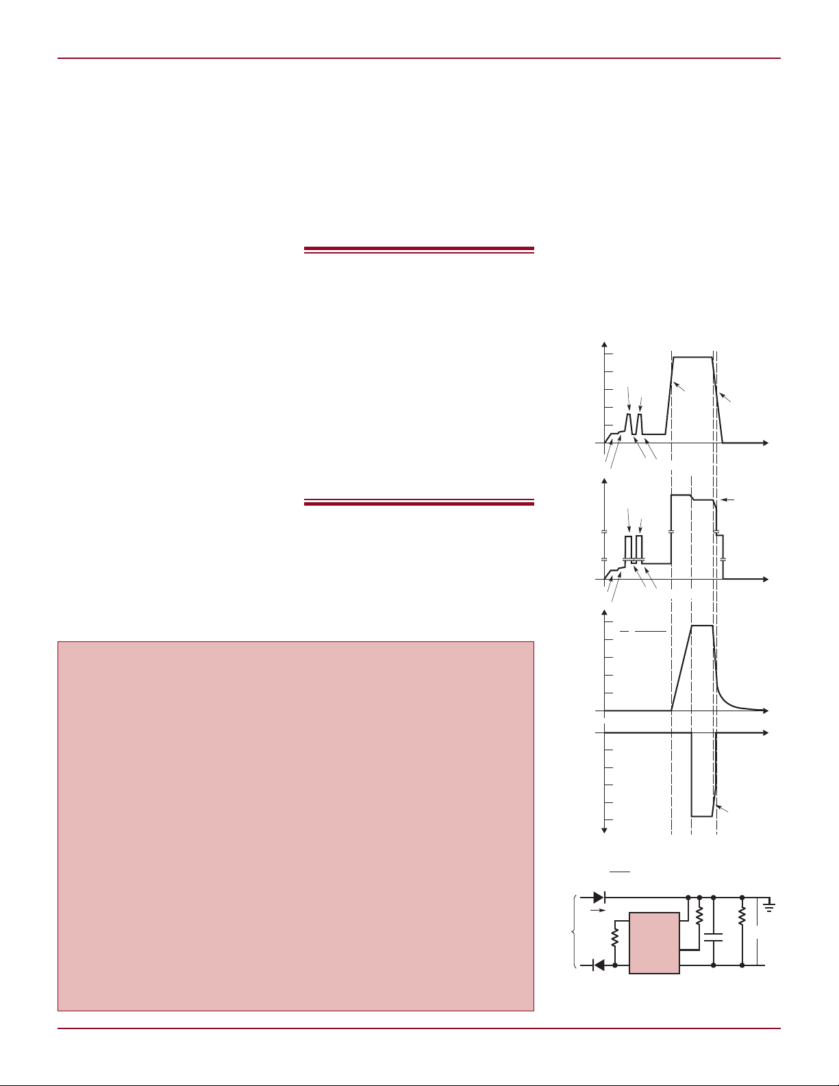
Figure 1. Example of 2-event
classification waveform
Linear Technology Magazine • January 2009
DESIGN FEATURES L
GND
R
S
10k
R10
100k
PWRGD
D9
MMBD4148
Q1
FMMT2222
–54V
4265 F08
TO
PSE
LTC4265
ACTIVE-LOW ENABLE
V
IN
V
OUT
V
+
PD
LOAD
GND
R
S
10k
R9
100k
PWRGD
D9
5.1V
MMBZ5231B
–54V
TO
PSE
LTC4265
ACTIVE-LOW ENABLE
V
IN
V
OUT
PD
LOAD
–54V
TO
PSE
ACTIVE-HIGH ENABLE
PD
LOAD
RUN
SHDN
GND
PWRGD
LTC4265
V
IN
V
OUT
OPTION 1: SERIES CONFIGURATION FOR
ACTIVE LOW/LOW IMPEDANCE OUTPUT
–54V
TO
PSE
R
P
TO PD
LOAD
GND
LTC4265
V
IN
T2PSE
V
+
OPTION 2: SHUNT CONFIGURATION FOR
ACTIVE HIGH/OPEN COLLECTOR OUTPUT
–54V
TO
PSE
R
P
TO PD
LOAD
GND
LTC4265
V
IN
V
OUT
T2PSE
V
+
T1
T1 = COILCRAFT ETHI-230LD
BR1, BR2 = DF1501S
TVS
TO PHY
36V
100k
10k
10k
D1
BR1
+
–
BR2
+
–
0.1µF
100V
C1
GND
LTC4265
V
IN
SHDN
V
OUT
+
–
ISOLATED
WALL
ADAPTER
PD
LOAD
RX
–
6
RX
+
3
TX
–
2
TX
+
RJ45
1
7
8
5
4
SPARE
–
SPARE
+
are required in other power interface
products to set thresholds, signature
resistance, and current limits. The
LTC4265 comes in a low profile,
thermally enhanced, 4mm × 3mm
DFN package.
What is 2-Event
Classification?
The IEEE 802.3at establishes two
ways to communicate the presence of
a Type-2 PSE. The Layer 1 approach
requires a PSE to perform 2-event
classification, where classification
probing is performed twice. The Layer
2 approach requires the PSE to communicate over the high speed data line.
A Type-2 PD is required to recognize a
Type-2 PSE using either layer of communication. Layer 1 communication
using 2-event classification is included
in the IEEE 802.3at standard for the
benefit of PSEs/power injectors which
do not have access to the high speed
data line.
Since Layer 2 communications
takes place directly between the PSE
and the LTC4265 load, the LTC4265
concerns itself only with recognizing
2-event classification. Figure 1 shows
an example of a 2-event classification.
The 1st classification event occurs
when the PSE presents an input
voltage between 14.5V to 20.5V and
the LTC4265 presents a class 4 load
current. A Type-2 PSE then drops the
input voltage into the Mark voltage
range of 6.9V to 10V, signaling the
1st Mark event. The PD in the Mark
voltage range presents a load current
between 0.25mA to 4mA. A Type-2
PSE repeats this sequence, signaling
the 2nd Classification and 2nd Mark
event occurrence.
The Type-2 PSE then applies power
to the PD and the LTC4265 charges
up the reservoir capacitor C1 with a
controlled inrush current. When C1
is fully charged, and the LTC4265
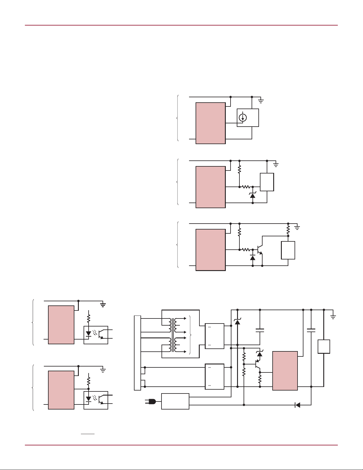
Figure 3. Examples of enabling/disabling the PD load via the complementary power good pins
Figure 2. Interfacing with the
Type-2 PSE via the T2PSE pin
Linear Technology Magazine • January 2009
Figure 4. Auxiliary power supply. Auxiliary power takes
precedence over PoE power (using the SHDN pin).
27

•
•
FDS2582
10.0k
33k
10µF
16V
237k
30.9Ω
82k 158k
332k
22.1k
1.2k
4.7nF
100pF
10µF
100V
0.1µF
100V
SMAJ58A
B1100 s 8 PLCS
2.2µF
100V
PA2431NL
PGND GND
SD_VSEC
OC
ISENSE
COMP
FB
VREF
SS_MAXDC
OUT
BLANK DELAY ROSC
LT1952
V
IN
V
CC
S
OUT
GND
R
CLASS
SHDN
LTC4265
T2PSE
V
IN
V
OUT
10µH
–54V
FROM
DATA
PAIR
–54V
FROM
SPARE
PAIR
•
5V
5A
220µF
6.3V
PSLVOJ227M(12)
FDS8880FDS8880
+
GND
GND 5V
2.2nF
2kV
BAS516
BAS516
10k
133Ω
0.1µF
1mH
DO1608C-105
IRF6217
4.7nF
250V
50mΩ
5.1Ω
158k
0.22µF
5.1Ω
1nF
5.1Ω
1nF
6.8µH
PG0702.682
+
2k
PS2801-1-L
PS22801-1-L
BC857BF
TLV431A
1.5k
33k 22k
0.1µF
10nF
11.3k
3.65k
51k 20k
T2P (TO MICROCONTROLLER)
BAS516
BAS516
18V
PDZ18B
V
CC
LOAD CURRENT (A)
0.5
EFFICIENCY (%)
80
85
90
5
756570
1.5 21
32.5
4 4.53.5
95
42V
50V
57V
L DESIGN FEATURES
declares power good, the T2PSE output
presents an active low signal, or low
impedance output with respect to VIN,
which alerts the PD load that a Type-2
PSE is present and 25.5W applications
may operate.
In essence, a Type-2 PSE recognizes
a Type-2 PD when the PSE classifies
the PD and sees a class 4 load current.
A Type-2 PD recognizes a Type-2 PSE
when the PSE classifies twice.
Interfacing to the LTC4265
The LTC4265 has three output signals
that interface to other blocks within
a PD. The Type-2 PSE indicator bit
(T2PSE) alerts the PD load that it may
consume the full 25.5W available in
the new IEEE 802.3at specification.
Two complementary power good pins
(PWRGD and PWRGD) are typically
used to enable a DC/DC converter
after the PD is fully powered.
When a Type-2 PSE completes the
2-Event classification sequence, the
LTC4265 recognizes this sequence,
and provides an indicator bit, declaring
the presence of a Type-2 PSE. The open
drain output provides the capability
to use this signal to communicate to
the PD load.
Figure 2 shows two interface options using the T2PSE pin and an
optoisolator. The T2PSE pin is active
low and connects to the optoisolator
to communicate across the isolation
barrier. The pull up resistor RP is
sized according to the requirements
of the optoisolator operating current,
the pull-down capability of the T2PSE
pin, and the choice of V+. V+ can come
from the PoE supply rail (which the
LTC4265 GND is tied to), or from the
voltage source that supplies power to
the DC/DC converter. The former has
the advantage of not drawing power
unless T2PSE is declared active.
Figure 3 shows options for interfacing the LTC4265 power good pin
to the PD load, usually via the run/
enable/shutdown pins of a DC/DC
converter.
The active high PWRGD pin features
an open collector output referenced
to V
with the run/enable pin of a DC/DC
converter. When the PD is powered
28
, which can interface directly
OUT
Figure 5. PoE-based self-driven synchronous forward power supply
Linear Technology Magazine • January 2009

•
100k12k
•
•
•
•
33mΩ
FDS2582
14k
3.01k
20Ω
39k
15µF
16V
29.4k
383k
30.9Ω
BAS21
2.2k 38.3k
10k
51k
1nF
10k 20k
15Ω
15Ω
150Ω
PE-68386
BAT54
100Ω
33pF
10µF
100V
0.1µF
100V
SMAJ58A
B1100 s 8 PLCS
2.2µF
100V
0.1µF
4.7nF
2.2nF
MMBT3906 MMBT3904
1µF
1µF
16V
PA2467NL
t
ON
SYNC
PGDLY
UVLO
SENSE
–
V
C
SENSE
+
R
CMP
ENDLY OSC SFST
LT3825
GND
SG
FB
V
CC
SG
SG
PG
C
CMP
GND
R
CLASS
SHDN
LTC4265
T2PSE
V
IN
V
OUT
10µH
–54V FROM
DATA PAIR
–54V FROM
47pF
10µF
16V
0.33µH
12V
2A
47µF
16V
FDS3572
+
GND
4
5
1
8
GND
LTV357TA
T2P
(TO MICROCONTROLLER)
2.2nF
2kV
470pF
2kV
+
LOAD CURRENT (A)
0.2 0.4
EFFICIENCY (%)
85
89
87
2.0
81
83
77
79
0.6 0.8
1.21.0
1.6 1.81.4
93
91
57V48V
EXCLUDING BRIDGES
42V
up by the PSE, the PWRGD pin is
high impedance with respect to V
An internal 14V clamp protects the
DC/DC converter from excessive voltage. The PWRGD pin is also designed
to become high impedance when the
SHDN pin is invoked in an auxiliary
power application. This prevents the
PWRGD pin from interfering with the
converter operation when auxiliary
power is present.
The active low PWRGD pin connects
to an internal, open drain MOSFET
referenced to V
and can interface
IN
directly to the shutdown pin of a DC/
DC converter. When the PD is powered
up by the PSE, the PWRGD pin is low
impedance with respect to VIN.
Configuring a PD for
Auxiliary Power
In many applications, the PD can
run from the PoE port and/or from
an auxiliary power source such as a
wall adapter. Auxiliary power can be
injected into an LTC4265-based PD at
the input of the LTC4265, the output
of the LTC4265, or even the output
of the DC/DC converter. Some PD
applications may also prioritize the
auxiliary supply or the PoE supply,
and/or require a seamless transition
between PoE and auxiliary power.
Figure 4 shows the most common
auxiliary power method where auxiliary power is injected between the PD
interface and the DC/DC converter. In
this example, the auxiliary port injects
48V onto the line via diode D1. The
components surrounding the SHDN
pin are selected so that the LTC4265
disconnects power to the output when
the auxiliary supply reaches 36V.
This configuration is an auxiliarydominant configuration. That is, the
auxiliary power source supplies the
power even if PoE power is already
present. When the auxiliary power
is applied, the PoE channel stops
drawing power. The PSE at this point
recognizes that the PD does not draw
any current and may cease power
delivery to the PD.
This configuration also provides
a seamless transition from PoE to
auxiliary power when auxiliary power
Linear Technology Magazine • January 2009
continued on page 34
OUT
.
DESIGN FEATURES L
Figure 6. High efficiency 12V isolated power supply
29

L DESIGN IDEAS
RUN/SS2
2V/DIV
V
IN
20V/DIV
V
OUT
1V/DIV
FAULT
2V/DIV
TIME 100µs/DIV
RUN/SS2
2V/DIV
V
IN
20V/DIV
V
OUT
1V/DIV
FAULT
2V/DIV
TIME 100ms/DIV
RUN/SS2
2V/DIV
V
IN
20V/DIV
V
OUT
1V/DIV
FAULT
2V/DIV
TIME 2ms/DIV
Figure 5. Transition to ride-through mode Figure 6. Complete ride-through event Figure 7. End of ride-through event
by software perhaps, from the time
FAULT goes away until full current
is demanded.
The LT3509 prevents inrush
currents at start-up with a current
limiting soft-start feature, which allows the available output current to
ramp up slowly. Both the peak current
limit and the valley current limit (the
one sensed through the catch diodes)
are controlled by the voltage on the
RUN/SS pins, so as capacitors C6
and C7 charge up, the output cur rent slowly increases to its normal
maximum value. An example of the
soft-start characteristic is shown in
Figure 3.
LTC4265, continued from page 29
is applied. That is, the DC/DC converter continues to operate through the
power transition. But the transition
from auxiliary power to PoE power
(when the auxiliary is removed) is not
seamless since a PSE must redetect
the PD before applying power.
Guidelines for Pairing
the LTC4265 with a
DC/DC Converter
The LTC4265 can be paired with just
about any DC/DC converter, but two
are particularly well suited to Type-2
Power over Ethernet Applications:
the LT3825 flyback controller and
LT1952 forward controller. Forward
and flyback converters satisfy the
electronic isolation requirement in
the IEEE 802.3af and IEEE 802.3at
specifications. In addition to the topology requirements, the LT3825 and
LT1952 controllers are selected based
on their ability to tolerate the wide PoE
line voltage range, which varies from
36V to 57V.
Demonstration
and Test Results
The ride-through performance the application of Figure 1 is tested using the
setup shown in Figure 4. A switched
supply produces either a normal input
or an overvoltage transient. The output
is connected to an active load circuit
with ON/OFF controlled by the FAULT
signal. Figure 5 shows the start of the
overvoltage event on a fast time base
to show the step that occurs as the
regulator shuts off, but before the load
is reduced. Figure 6 shows the entire
400ms transient and the droop that
happens when there is no output but
also very little load. Figure 7 shows
As PoE power levels increase, the
Schottky diode typically placed at
the output of the secondary winding
becomes an efficiency drain as it dissipates more power with increased
output current. In addition, the output
diode requires a considerably large
heat sink and board area to displace
the heat.
For these reasons, many powerhungry PDs are better served by
synchronous DC/DC topologies,
where the output diode is replaced with
an active switch synchronized to the
operation of the controller. Both the
LT3825 and LT1952 include built-in
synchronous drivers, enabling the use
of an active switch.
Figure 5 shows the L TC4265
paired with an LT1952 in a self-driven
synchronous forward power supply
configuration. Figure 6 shows the
LTC4265 paired with a LT3825. This
is a synchronous flyback power supply configuration with no optoisolator
the end of the event on an expanded
timescale.
Conclusion
Overvoltage transients are a fact of life
in automobile and industrial power
systems. The LT3509, combined with
a small, low cost capacitor, can be
used to both protect components from
overvoltage transients and allow the
downstream systems to ride through
the event without having to completely
reset. It is possible to ride through an
overvoltage transient of even several
hundred milliseconds, provided a brief
interruption of service can be tolerated.
L
feedback. The LT3825 may also be
configured for a forward topology.
These are not the only DC/DC
converter solutions that work well
with the LTC4265. The LTC4265 can
be easily applied in applications that
already have a DC/DC converter.
Conclusion
The LTC4265 PD interface provides
the features required in a PD interface
to operate under the IEEE 802.3at
standard with minimum component
count. Since all of the features (signature resistance, UVLO, OVLO, inrush
current, and thermal protection) are
built in, little is needed around its low
profile 4mm × 3mm DFN package to
create a complete PoE Type-2 interface.
Simply pair it with a PoE-ready DC/DC
converter by hooking up the Type-2
and power good indicator pins, and
a high power PD is ready to go. Add
to this the ability to handle auxiliary
power, and the LTC4265 proves a
versatile PoE+ tool.
L
34
34
Linear Technology Magazine • January 2009
 Loading...