

An Easy Way to Add Auxiliary Control Functions to
, LTC, LT and LTM are registered trademarks of Linear Technology Corporation.
Hot Swap is a trademark of Linear Technology. All other trademarks are the
property of their respective owners.
UV V
DD
SENSE
LTC4215GN
LT1761-SD
GATE
INTV
CC
TIMER GND
GND
ENADR0 ADR1
SOURCE
OV
SDAI
SDA0
SCL
GPIO2
ON
IN
SHDN
OUT
ADJ
FB
GPIO1
GPIO3
ADIN
SS
PLUG-IN
CARD
R5
10Ω
15k
C1
22nF
C
SS
68nF
R
S
0.004Ω
Si7880DP
22.1k
1%
12V/5A
OUTPUT
5V
3.0k
1%
4.7k 50k
50k
768k
249k
C
OUT
C
F
0.1µF
133k
1%
4.75k
1%
13.7k
1%
BACKPLANE
GND
ALERT
SCL
SDA
V
IN
12V
C
TIMER
1µF
4.7µF
0.1µF
NC
Hot Swap Cards – Design Note 421
Mark Thoren
Introduction
A Hot Swap™ controller is essential to any system in
which boards are inserted into a live backplane. The
controller must gently ramp up the supply voltage and
current into the card’s bypass capacitors, thus minimizing disturbances on the backplane and to other cards.
Likewise, it must disconnect a faulty card from the
backplane if it draws too much current. The controller
also monitors undervoltage and overvoltage conditions
on the backplane supply, ensuring reliable operation of
the card’s circuitry. The LTC4215-1 takes the obvious
next step and integrates three general purpose I/O (GPIO)
lines and an accurate ADC into the Hot Swap controller
to provide quantitative information on board voltage
and current. Upgrading to the LTC4215-1 is analogous
to replacing a car’s venerable “Check Engine” light with
a modern dashboard information display.
Additional Control
There are many functions on a card that are considered
part of the “power gateway,” apart from the actual function
of the board (telecommunications, data acquisition, etc.)
These include sequencing power supplies, providing supply status information, monitoring pushbuttons, etc. The
LTC4215-1 GPIO pins are well suited to these functions.
Tying the ON pin high turns on the pass FET after a 100ms
power-on delay. Grounding the ON pin enables software
control of the FET. The state of the GPIO pins can be set
before enabling the FET, ensuring a known state when
downstream power is enabled. GPIO1 defaults high on
power up, and can sink 5mA. GPIO2 defaults high and can
sink 3mA. GPIO3 defaults low and can sink 100µA.
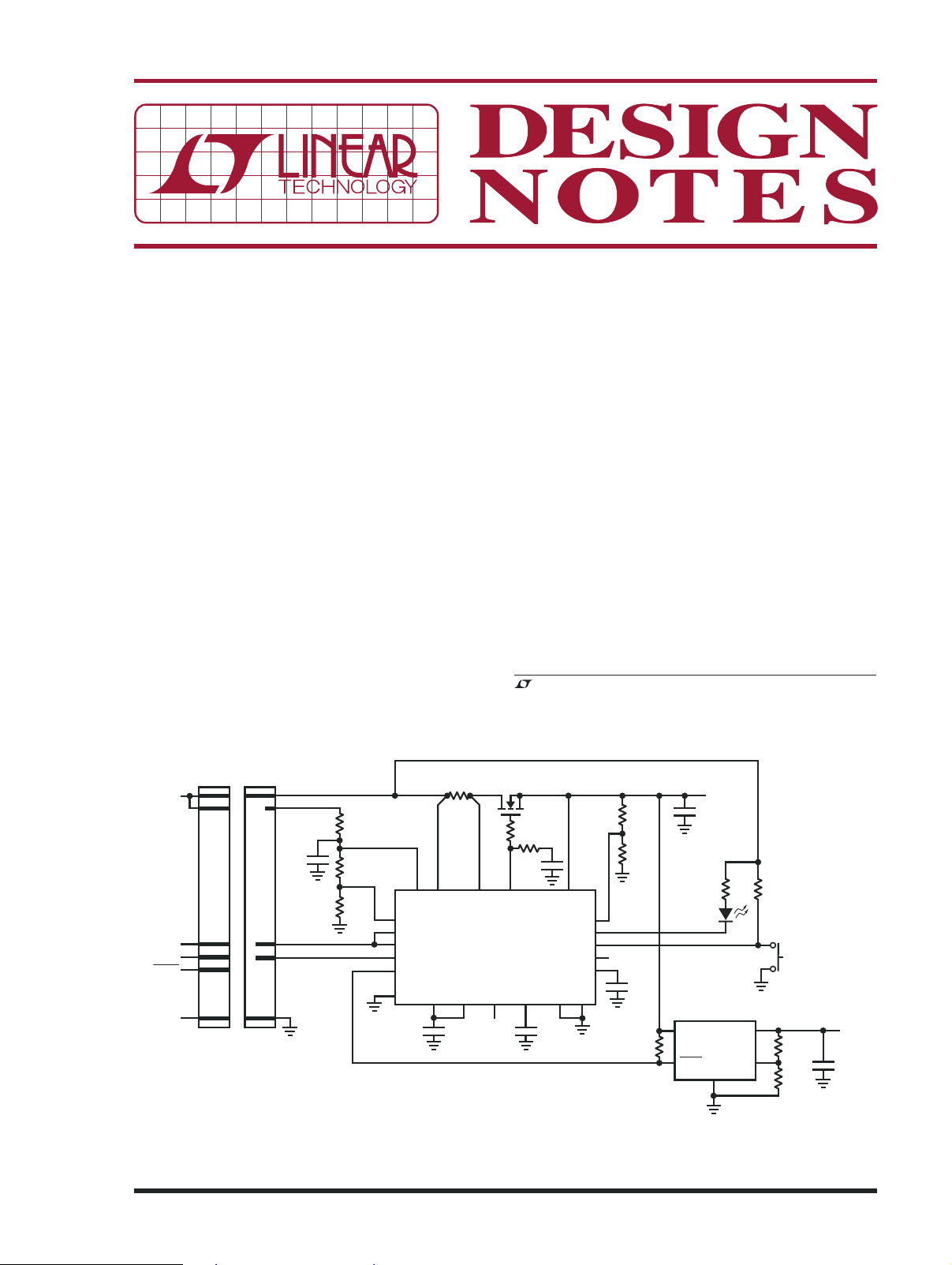
Figure 1. The LTC4215-1 in a Typical Card Resident Application
08/07/421
For instance, Figure 1 shows an application that monitors
V
CC
SENSE
GATE
TIMER/OFF
GND
ON
R
G
100Ω
R
C
68Ω
C
LOAD
10µF
16V
V
OUT
3.3V/6A
C
C
0.01µF
50V
0.1µF
10k
10k
10Ω
C
TIMER
0.22µF
16V
R
SENSE
0.007Ω
3.3V FROM
BACKPLANE
GPIOX
0.01µF
6
2
4
E2
4
3
1
5
+
Si4410DY
LTC4210-1CS6
V
CC
Y7
Y6
Y5
Y4
Y3
Y2
Y1
Y0
GND
A
B
C
G1
G2A
G2B
50k
×3
GPIO1
GPIO2
GPIO3
1k
3.3V
1k
5V
74HC138
a “request to remove card” pushbutton and lights an “okay
to remove” LED when the card is ready for removal. This
permits graceful shutdown of the card. For example, it
can transfer collected data before shutting down so that
it is not lost. GPIO1, which defaults high, controls the
LED. GPIO3 is reprogrammed as an input that monitors
the state of the pushbutton. The GPIO2 pin controls the
operation of an onboard regulator. This is important in
mixed signal circuits, where analog circuitry may need to
be powered up before digital signals are enabled.
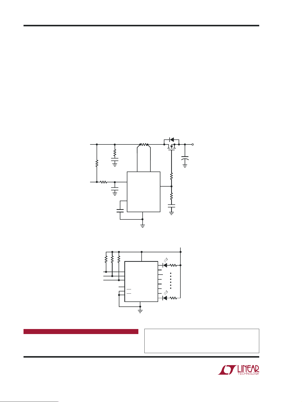
Figure 2 uses a GPIO pin to control an LTC4210-1 Hot Swap
controller, which in turn controls a 3.3V rail. Once again,
this is useful for sequencing supplies and may eliminate
the need for additional sequencing circuits.
Figure 3 uses all three GPIO pins to light one of eight
LEDs using a 74HC138 decoder. These can indicate
system status or power consumption. Other possible
functions include issuing a microprocessor reset, adding additional channels to the ADC using the GPIO pins
to control a multiplexer, or interfacing with an advanced
power supply sequencer such as the LTC2928.
Conclusion
The LTC4215-1 is a smart power gateway for Hot Swap
circuits. It provides fault isolation, closely monitors the
health of the power path, and provides an unprecedented
level of control over the inrush current profile. The three
general purpose I/O pins and a spare ADC channel allow
further control of power path and system initialization/
shutdown related functions.
Data Sheet Download
www.linear.com
Linear Technology Corporation
1630 McCarthy Blvd., Milpitas, CA 95035-7417
(408) 432-1900 ● FAX: (408) 434-0507 ● www.linear.com
Figure 2. Controlling an LTC4210-1
Figure 3.Controlling Eight Status LEDs
For applications help,
call (408) 432-1900, Ext. 2360
dn421 LT 0807 451K • PRINTED IN THE USA
LINEAR TECHNOLOGY CORPORATION 2007
 Loading...