


Power Monitor for Automotive and Telecom Applications
Includes ADC and I2C Interface – Design Note 452
Dilian Reyes
Introduction
The LTC®4151 is a high side power monitor that includes
a 12-bit ADC for measuring current and voltage, as well
as the voltage on an auxiliary input. Data is read through
2
the widely used I
C interface. An unusual feature in this
device is its 7 V to 80V operating range, allowing i t to cover
applications from 12V automotive to 48V telecom.
Automotive Power Monitoring
Automobile batteries serve more systems than ever
before, many of which operate when the battery is not
charging, such as information/entertainment systems or
devices plugged into the accessory socket.
The high input voltage of the LTC4151 is a good fi t for
monitoring power in high transient environments such
as automotive. Figure 1 shows the LTC4151 monitoring
up to 16A through a 5mΩ sense resistor at an accessory
2
socket, and feeding data via I
C to a microcontroller.
A portable GPS unit is used to illustrate the principle. In
this case it is powered up and charging its own internal
battery, drawing 396mA from the 12.1V supply. The 4.8W
of power is relatively low and thus calls for no immediate
need for alarm. However, a higher power device such as a
buil t-in DVD player with dual LCD displays or an external
60W thermoelectric cooler plugged into the accessory
socket would drain the battery considerably faster than
the GPS. The digital information from the LTC4151 high
resolution and accurate 12-bit ADC can be interpreted
and displayed on an in-dash screen, or used by the host
system to shut down the channel to avoid fully draining
the battery.
Telecom Power Monitoring with PoE
One major advantage of the wide range input voltage
of the LTC4151 is the ability to monitor higher voltage
applications such as those used in telecommunications. The emerging IEEE802.3af Power over Ethernet
(PoE) standard has gained much interest in the past
few years.
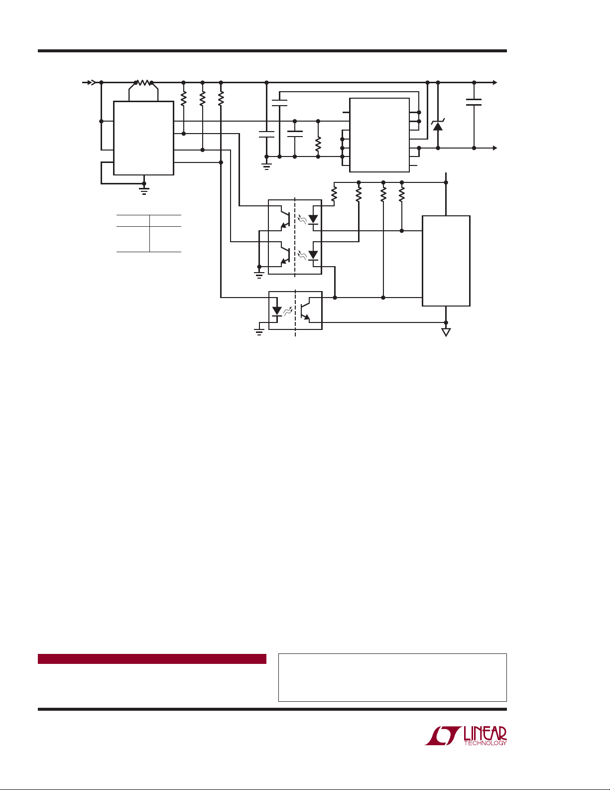
In Figure 2 the LTC4151-1 monitors the isolated 4 8V power
supply to the LTC4263 single port Power Sourcing Equipment (PSE) controller. Communication across isolation
through optocouplers to a microcontroller is simplifi ed
with the LTC4151-1’s split bidirect ional SDA line to separate
data in and data out. Pull-up resistors tie directly to the
48V supply for pins SCL and SDAI, which are internally
clamped to 6V, and inverted SDAO is confi gured to be
clamped by an optocoupler diode. With the low speed
optocouplers shown, the LTC4263 generating its own
L, LT, LTC and LTM are registered trademarks of Linear Technology Corporation.
All other trademarks are the property of their respective owners.
10/08/452
0.005Ω
SENSE
V
IN
ADR1
ADR0
2W
+
SENSE
LTC4151
GND
ADIN
SHDN
SCL
SDA
AUTO SOCKET GPS
–
2k
2k
μCONTROLLER
SCL
SDA
3.3V
V
DD
DN452 F01
12V
Figure 1. The LTC4151 Monitoring Voltage and Current of an Auto Socket with a GPS Unit
ISOLATED 48V
V
(44V TO 57V)
R
S
IN
0.1Ω
110
+
SENSE
2
V
IN
LTC4151-1
3
ADR1
4
ADR0
GND
SENSE
ADIN
SDAI
SDAO
SCL
R2
20k
R3*
8.25k
0.1μF
100V
**
f
SCL
3.33kHz
8
0.1μF
V
PWRMGT
1μF
MOCD207M
R
PM
12.7k
1%
1
R4
510Ω
LTC4263
LED
PWRMGT
MIDSPAN
LEGACY
V
SS
V
SS
OSC
R5
510Ω
V
DD5
ENFCLS
SD
V
DD48
OUT
OUT
ACOUT
R6
20k
R7
20k
0.1μF
100V
SMAJ58A
3.3V
TO PORT
MAGNETS
R1
20k
–
5
6
7
8
PD CLASS
CLASS 1
CLASS 2
CLASS 3
*R3 = 4 • 33k, 1/8W IN PARALLEL
**FASTER OPTOCOUPLERS PERMIT
100kHz OR 400kHz BUS OPERATIONS
V
PWRMGT
0.237V
0.417V
0.918V
7
6
5
1/2 MOCD207M
1
2
V
2
3
4
8
7
DD
SCL
μCONTROLLER
SDA
DN452 F02
Figure 2. The LTC4151-1 in a PoE Single Port PSE with the LTC4263. I2C Communication to an Isolated Microcontroller
5V supply, and the LTC4151 high voltage protected I2C
pins, a separate digital supply is not needed on the PoE
side, just the single isolated 48V supply.
Optional power clas ses (4W, 7W and 15.4W) c ategorize the
power requirements o f a Powered Device (PD) on the cable
end. The LTC4263 outputs a current to a power management resistor that is proportional to the power class of
the plugged-in PD. The LTC4151-1 measures the resulting
voltage through its auxiliar y ADC input and reports this to
the microcontroller, which in turn interprets what power
class is present. The microcontroller can then read the
current being drawn at the port to determine if the PD is
abiding by its power class, and confi rm that the supply
voltage to the PSE controller meets PoE standards.
multiport solution with monitoring at each port. This assists with the controller power management functions,
which utilizes the available power from an optimized
supply to the individual ports.
Additional bene fi ts of the LTC4151 is the integrated current
sense amplifi er, input volt age resistor divider, precise ADC
reference vol tage and channel select MUX. T hese improve
accuracy versus variances of external components and
also save on costs of discrete parts.
Conclusion
The LTC4151 is an easy to use but feature-rich power
monitoring device sui table for a wide variet y of automotive,
telecom and industrial applications. It provides accurate
voltage and current monitoring of a positive supply rail
The LTC4151 has a confi gurable address so multiple
from 7V to 80V via a simple I
2
C interface.
LTC4151s can operate on the same bus, allowing for a
Data Sheet Download
www.linear.com
Linear Technology Corporation
1630 McCarthy Blvd., Milpitas, CA 95035-7417
(408) 432-1900
●
FAX: (408) 434-0507 ● www.linear.com
For applications help,
call (408) 432-1900
dn452 LT/TP 1008 246K • PRINTED IN THE USA
© LINEAR TECHNOLOGY CORPORATION 2008
 Loading...