

DESIGN IDEAS L
V
BUS
USB
OVERVOLTAGE
PROTECTION
10µF
10µF
0.1µF 3.01k 1.02k
6.2k
TO µCONTROLLER
SYSTEM
LOAD
CLPROG PROG
LTC4099
GND
SW
3.3µH
NTC
OVSENS
I
2
C
OVGATE
V
OUT
BAT
BATSENS
NTCBIAS
2
Li-Ion
100k
R
NTC
100k
T
+
R
NTC
= VISHAY NTHS0402N01N1003FE, 0402 ,100k, CURVE 1, 1%, Pb FREE
Battery Conditioner Extends the
Life of Li-Ion Batteries
Introduction
Li-Ion batteries naturally age, with an
expected lifetime of about three years,
but that life can be cut very short—to
under a year—if the batteries are mishandled. It turns out that the batteries
are typically abused in applications
where intelligent conditioning would
otherwise significantly extend the
battery lifetime. The LTC4099 battery
charger and power manager contains
an I2C controlled battery conditioner
that maximizes battery operating life,
while also optimizing battery run time
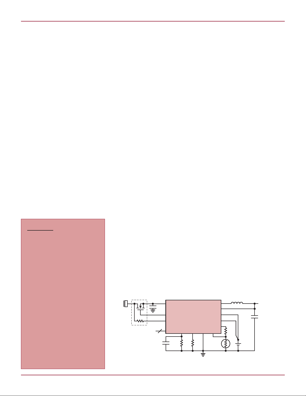
and charging speed (see Figure 1).
The Underlying Aging
Process in Li-Ion Batteries
Modern Li-Ion batteries are constructed of a graphite battery cathode,
cobalt, manganese or iron phosphate
battery anode and an electrolyte that
transports the lithium ions.
The electrolyte may be a gel, a
polymer (Li-Ion/Polymer batteries)
DESIGN IDEAS
Battery Conditioner Extends
the Life of Li-Ion Batteries .................29
George H. Barbehenn
EMI Certified Step-Down Converter
in 15mm × 9mm µModule® Package
Produces 1A, 0.8V
3.6V
36VIN .......................................31
IN –
David Ng
Using a Differential I/O Amplifier
in Single-Ended Applications ............32
Glen Brisebois
OUT
–10V
OUT
from
or a hybrid of a gel and a polymer.
In practice, no suitable polymer has
been found that transports lithium
ions effectively at room temperature.
Most ‘pouch’ Li-Ion/Polymer batteries
are in fact hybrid batteries containing a combination of polymer and gel
electrolytes.
The charge process involves lithium
ions moving out of the battery cathode material, through the electrolyte
and into the battery anode material.
Discharging is the reverse process.
Both ter minals either release or
absorb lithium ions, depending on
whether the battery is being charged
or discharged.
The lithium ions do not bond with
the terminals, but rather enter the
terminals much like water enters a
sponge; this process is called “intercalation.” So, as is often the case
with charge-based devices such as
electrolytic capacitors, the resulting
charge storage is a function of both
the materials used and the physical
structure of the material. In the case
of the electrolytic capacitor, the foil is
etched to increase its surface area. In
the case of the Li-Ion battery the terminals must have a sponge-like physical
makeup to accept the lithium ions.
The choice of battery anode material
(cobalt, manganese or iron phosphate)
determines the capacity, safety and
aging properties of the battery. In
particular, cobalt provides superior
by George H. Barbehenn
capacity and aging characteristics,
but it is relatively unsafe compared to
the other materials. Metallic lithium
is flammable and the cobalt battery
anode tends to form metallic lithium
during the discharge process. If several
safety measures fail or are defeated,
the resulting metallic lithium can fuel
a “vent with flame” event.
Consequently, most modern Li-Ion
batteries use a manganese or iron
phosphate-based battery anode. The
price for increased safety is slightly reduced capacity and increased aging.
Aging is caused by corrosion, usually oxidation, of the battery anode
by the electrolyte. This reduces both
the effectiveness of the electrolyte in
lithium-ion transport and the spongelike lithium-ion absorption capability
of the battery anode. Battery aging
results an increase of the battery series
resistance (BSR) and reduced capacity,
as the battery anode is progressively
less able to absorb lithium ions.
The aging process begins from the
moment the battery is manufactured
and cannot be stopped. However, battery handling plays an important role
in how quickly aging progresses.
Conditions that Affect
the Aging Process
The corrosion of the battery anode is
a chemical process and this chemical
process has an activation energy probability distribution function (PDF). The
Dual Output µModule DC/DC Regulator
Produces High Efficiency 4A Outputs
from a 4.5V to 26.5V Input ................33
Alan Chern
All-in-One Power for Portables:
Single IC Replaces Battery Charger,
Pushbutton Controller, LED Driver
and Five Voltage Regulator ICs ..........34
Marty Merchant
Maximize the Performance of 16-Bit,
105Msps ADC with Careful IF Signal
Chain Design .....................................36
Clarence Mayott and Derek Redmayne
Linear Technology Magazine • December 2009
Figure 1. The LTC4099 with I2C controlled battery conditioner
2929

L DESIGN IDEAS
BATTERY VOLTAGE (V)
3.6
BATTERY CURRENT (mA)
60
90
120
30
3.8 4.0
3.7
3.9 4.1 4.2
0
150
BATTERY CONDITIONER ENABLED
TEMPERATURE > 60°C
V
NTC
/ V
NTCBIAS
< 0.219
V
BUS
= 0V
~
TEMPERATURE (°C)
0
CAPACITY LOSS (%)
20
30
40
10
20 40
10
30 50 60
0
50
CAPACITY LOSS AFTER ONE YEAR
100% SoC
40% SoC
activation energy can come from heat
or the terminal voltage. The more activation energy available from these two
sources the greater the chemical reaction rate and the faster the aging.
Li-Ion batteries that are used in
the automotive environment must
last 10 to 15 years. So, suppliers of
automotive Li-Ion batteries do not recommend charging the batteries above
3.8V. This does not allow the use of
the full capacity of the battery, but is
low enough on the activation energy
PDF to keep corrosion to a minimum.
The iron phosphate battery anode has
a shallower discharge curve, thus
retaining more capacity at 3.8V.
Battery manufacturers typically
store batteries at 15°C (59°F) and a
40% state of charge (SoC), to minimize
aging. Ideally, storage would take
place at 4% or 5% SoC, but it must
never reach 0%, or the battery may
be damaged. Typically, a battery pack
protection IC prevents a battery from
reaching 0% SoC. But pack protection
cannot prevent self-discharge and the
pack protection IC itself consumes
some current. Although Li-Ion batteries have less self-discharge than most
other secondary batteries, the storage
time is somewhat open-ended. So, 40%
SoC represents a compromise between
minimizing aging and preventing damage while in storage (see Figure 2).
In portable applications, the reduction in capacity from such a reduced
SoC strategy is viewed negatively in
marketing specifications. But it is
sufficient to detect the combination
Figure 2. Yearly capacity loss vs temperature
and SoC for Li-Ion batteries
of high ambient heat and high battery SoC to implement an algorithm
that minimizes aging while ensuring
maximum capacity availability to the
user.
Battery Conditioner
Avoids Conditions
that Accelerate Aging
The LTC4099 has a built-in battery
conditioner that can be enabled or
disabled (default) via the I2C interface.
If the battery conditioner is enabled
and the LTC4099 detects that the
battery temperature is higher than
~60°C, it gently discharges the battery
to minimize the effects of aging. The
LTC4099 NTC temperature measurement is always on and available to
monitor the battery temperature. This
circuit is a micropower circuit, drawing only 50nA while still providing full
functionality.
Figure 3. Battery discharge current vs voltage
for the LTC4099 battery conditioning function
The amount of current used to discharge the battery follows the curve
shown in Figure 3, reaching zero when
the battery terminal voltage is ~3.85V.
If the temperature of the battery pack
drops below ~40°C and a source of
energy is available, the LTC4099 once
again charges the battery. Thus, the
battery is protected from the worstcase battery aging conditions.
Conclusion
Although the aging of Li-Ion batteries
cannot be stopped, the LTC4099’s
battery conditioner ensures maximum
battery life by preventing the batterykilling conditions of simultaneous high
voltage and high temperature. Further,
the micropower, always on NTC monitoring circuit ensures that the battery
is protected from life-threatening
conditions at all times.
L
LTC2262, continued from page 25
lines used by the LTC2175, and allows
it to be packaged in a space saving
7mm × 8mm QFN package.
The dual version of the LTC2262 is
the LTC2268. It dissipates 299mW of
total power, or 150mW per ADC. It also
has LVDS serial output lines that reduce space, and allow the LTC2268 to
be in a 6mm × 6mm QFN package.
The dual and quad versions of
LTC2262 are available in 12- and
14-bit versions, in speed grades from
25Msps up to 125Msps. A complete
list of the variant is shown in Table 1.
30
30
Each device shares the excellent AC
performance of the LTC2262, and
features better than 90dB of channel-to-channel isolation. The serial
outputs of the multiple channel parts
mitigate the effect of digital feedback,
producing a clean output spectrum.
In sum, the performance of LTC2262
is not sacrificed when migrating into
multiple channel parts.
Conclusion
The LTC2262 ultralow-power ADC
simplifies design with a unique combi-
nation of features. Digital noise can be
reduced by using DDR LVDS signaling,
alternate bit polarity mode, or the data
randomizer. The number of data lines
needed to transmit 14 bits of data can
be reduced to seven with DDR CMOS
signaling, which simplifies layout. The
LTC2262 is part of a pin-compatible
family of 12-bit and 14-bit ADCs with
sample rates from 25Msps to 150Msps,
with power consumption ranging from
35mW at 25Msps up to 149mW at
150Msps while maintaining excellent
AC performance characteristics.
Linear Technology Magazine • December 2009
L
 Loading...