

Page 1
High Effi ciency USB Power Management System Safely Charges
Li-Ion/Polymer Batteries from Automotive Supplies
– Design Note 464
George H. Barbehenn
Introduction
Automotive power systems are unforgiving electronic
environments. Transients to 90V can occur when the
nominal voltage r ange is 10V to 15V (ISO7637), along wi th
b at t er y r ev er sa l i n s om e c as es. It ’s fai rl y s t ra i gh t for w ar d
to build automotive electronics around this system, but
increasingly end users want to operate portable electronics, such as GPS systems or music/video players,
and to charge their Li-Ion batteries from the automotive
battery. To do so requires a compact, robust, effi cient
and easy-to-design charging system.
Complete USB/Battery Charging Solution for Use in
Large Transient Environments
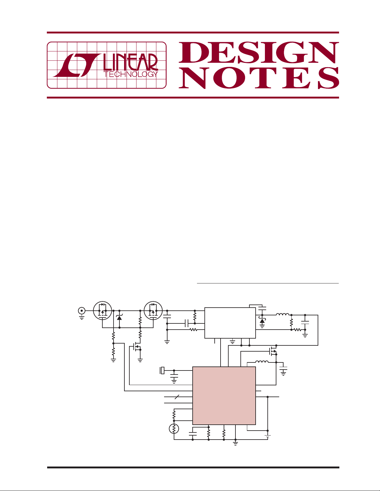
Figure 1 shows such a design. This complete PowerPat h™
manager and bat tery charger system se amlessly charges
the Li-Ion battery from a wide ranging high voltage or
USB source.
AUTOMOTIVE,
FIREWIRE,
ETC.
HVIN
M1
ZXMP10A18G
R3
33k
R4
10k
D1
MMBZ5240BLT1G
10V
OVGATE
M2
ZXMP10A18G
R5
10k
R1
1k
M3
ZXMN10A08E6
USB
TO μC
TO μC
V
IN
C6
C1
68nF
4.7μF
C2
10μF
0805
15-17
R7
100k
R8
T
100k
In this circuit, the LTC
Ion battery charger controls an LT3480 HV step-down
regulator. The LTC4098’s Bat-Track™ feature provides
a high effi ciency, low power dissipation battery charger
from low and high voltages alike. The Bat-Track feature
controls an internal input current-limited switching regulator to regulate V
OUT
maximizes battery charger effi ciency, and thus minimizes
power dissipation by operating the battery charger with
minimal headroom. Furthermore, the Bat-Track feature
reduces charge time by allowing a charge current greater
than the USB input current limit—the switching regulator
behaves like a transformer exchanging output voltage for
output current.
The LTC4098 can extend the Bat-Track concept to an
auxiliary regulator via the WALL and V
suffi cient voltage is present on WALL, Bat-Track takes
L, LT, LTC and LTM are registered trademarks and PowerPath and Bat-Track are
trademarks of Linear Technology Corporation. All other trademarks are the property of
their respective owners.
4
V
IN
R2
13
R6
40.2k
2
1
8
4
5
150k
5
RUN/SS
10
R
V
BUS
OVGATE
OVSENS
D0–D2
CHRG
NTCBIAS
NTC
CLPROG PROG
C3
0.1μF
0603
LT3480
T
PG GNDV
C
7
9
11 1 6
20 18 19 14
VCWALL ACPR
LTC4098
3 7 9, 21 6
R9
2.94k
GNDSWBATSENS
R10
1k
®
4098 USB power manager/Li-
to approximately V
BD
2
BOOST
SYNC
V
IDGATE
OUT
BAT
C7
0.47μF
3
SW
8
FB
L1
3.3μH
12
10
11
+
Li-Ion
DN464 F01
L2
10μH
M4
SYSTEM
LOAD
C5
10μF
0805
R11
499k
R12
100k
BAT
C
HVBUCK
+ 0.3V which
pins. When
C4
22μF
Figure 1. LTC4098 USB Power Manager/Li-Ion Battery Charger Works with an LT®3480 HV Buck Regulator to Accept Power
from an Automotive Environment or Firewire System. Overvoltage Protection Protects Both ICs and Downstream Circuits
05/09/464
Page 2
control of the auxiliary regulator’s output via the VC pin,
maintaining the regulator’s output at V
BAT
+ 0.3V.
The LTC4098 also includes an over voltage protec tion function—important in volatile supply voltage environments.
Overvoltage protection shuts off a protection N-channel
MOSFET (M2) when the volt age at the OVSENSE pin exceeds
approximately 6V. The upper limit of voltage protection is
limited only by the breakdown voltage of the MOSFET, and
by the current fl owing into the OVSENS pin.
Overvoltage Protection Covers the Entire Battery
Charger/Power Manager System
The overvoltage protection function of the LTC4098 can
protect a ny part of the circui t. In Figure 1, the pro tection has
been extended to the LT3480 V
input. The overvoltage
IN
shutdown threshold has been set to 24V. This threshold
provides ample margin against destructive overvoltage
events without interfering with normal operation.
In Figure 1, M1 is a P-channel MOSFET that provides
reverse volt age protection, wherea s M2 is the overvoltage
protection MOSFET, and M3 level-shifts the OVGATE
output of the LTC4098.
If the HVIN voltage is less than zero, the gate and source
v ol t a ge s of bo t h M 1 a n d M 2 ar e h e ld at g ro un d th r ou g h R 3,
R4, and R5, ensuring that they are of f. If the HVIN volt age is
betwe en 8V and approximately 24V, the gat e of M3 is driven
high via the LTC4098’s OVGATE pin. This turns on M1 and
M2 by pulling their gates 7V to 10V below their sources via
M3, D1, R1 and R5. With M1 and M2 on current fl ows from
HVIN to V
and the system operates normally.
IN
If the HVIN input exce eds approximately 24V, the LTC4098
drives the gate of M3 to ground, which allows R5 to
reduce the V
and disconnecting HVIN from V
M1, M2 and M3 have a BV
of M1 and M2 to zero, shutting them off
GS
.
IN
of 100V, so that this circuit
DSS
can tolerate voltages of approximately –30V to 100V. It
will operate normally from 8V to approximately 24V. This
combination is ideal for the harsh automotive environment,
providing a robust, low co st and effect ive solution for Li-Ion
battery charging from an automotive power system.
Finally, setting the OVSENS resistor divider requires some
care. For an OVSENS voltage between approximately 2V
and 6V, V
OVGATE
= 1.9 • V
. OVSENS is clamped at
OVSENS
6V and the current into (or out of) OVSENS should not
exceed 10mA. The chos en resistor divider at tenuates HVIN
by a factor of 4, so M3 has suffi cient gate voltage to turn
on when HVIN exceeds approximately 8V. When HVIN
= 100V, the current into OVSENS is just 2.25mA—well
below the 10mA limit.
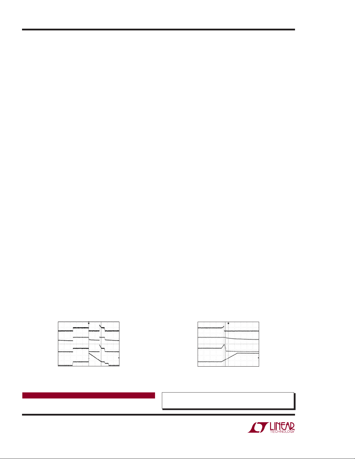
As shown in Figure 2, V
is only present when HVIN
IN
is in the 8V to 24V region. Figure 3 shows a close-up
centered on the load dump ramp. The ISO7637 test
ramp rises from 13.2V to 90V in 5ms. There is a 220μs
turn-off delay—OVGATE going low to the gates of M1
and M2—which results in an overshoot on V
maximum value of this overshoot is 3.5V (V
. The
IN
VIN(MAX)
≈
27.5V). The magni tude of this overshoot can be calcul ated
for different ramp rates, such that
V
OVERSHOOT
where ΔV = (90V – 13.6V), Δt = 5ms, and t
so, V
OVERSHOOT
= ΔV/Δt • t
= 3.36V.
DELAY
DELAY
= 220μs,
I f l e ss de la y, a nd th us le s s o ve rs ho o t, is de si re d, a n a c t i ve
turn-off circuit can reduce the delay from OVGATE to the
gates of M1 and M2 to a few microseconds.
Conclusion
The LT3480 high volt age step-down regul ator and LTC40 98
Li-Ion/Polymer battery charger, combined with a few
extern al components, produce a robust high per formance
Li-Ion charger suitable for port able electronics plugged into
an automotive power source and maintain compatibility
with USB power. The circuit provides all the functionality
that customer s expect, along with volt age protection from
battery reversal and load dump transients.
TRACE 1 = OVGATE
10V/DIV
TRACE 2 = HVBUCK
5V/DIV
TRACE 3 = V
IN
20V/DIV
TRACE 4 = HVIN
50V/DIV
200ms/DIV
DN464 F02
Figure 2. Overvoltage Protection Through
Input Transients per ISO7637 Standards
Data Sheet Download
www.linear.com
Linear Technology Corporation
1630 McCarthy Blvd., Milpitas, CA 95035-7417
(408) 432-1900
●
FAX: (408) 434-0507 ● www.linear.com
TRACE 1 = OVGATE
10V/DIV
TRACE 2 = HVBUCK
5V/DIV
TRACE 3 = V
IN
20V/DIV
TRACE 4 = HVIN
50V/DIV
2ms/DIV
DN464 F03
Figure 3. Closeup of Figure 2 Waveforms
Showing Overshoot on HVIN
For applications help,
call (978) 656-4700, Ext. 3752
dn464fa LT/TP 0509 REV A 155K • PRINTED IN THE USA
© LINEAR TECHNOLOGY CORPORATION 2009
 Loading...