

advertisement
Universal Li-Ion Battery Charger Operates from USB and
6V to 36V Input in Just 2cm2 – Design Note 395
Liu Yang
Introduction
There are a number of advantages to offering USB and
high input voltage power and battery-charging capability in handheld devices such as GPS navigators, PDAs,
digital still cameras, photoviewers and MP3 players. For
instance, charging and operation from USB offers the
obvious convenience of no t requiring a travel adapter. High
voltage sources, such a s Firewire and 12V to 24V adapters
are even better, since they provide faster charging than
USB and allow charging in more places, such as in the car.
Nevertheless, there is an important design consideration
with high voltage power sources: the voltage difference
between the high voltage source and the battery in the
handheld is very large. Since a line ar charger cannot handle
the power dissipation, a switching charger is required.
®
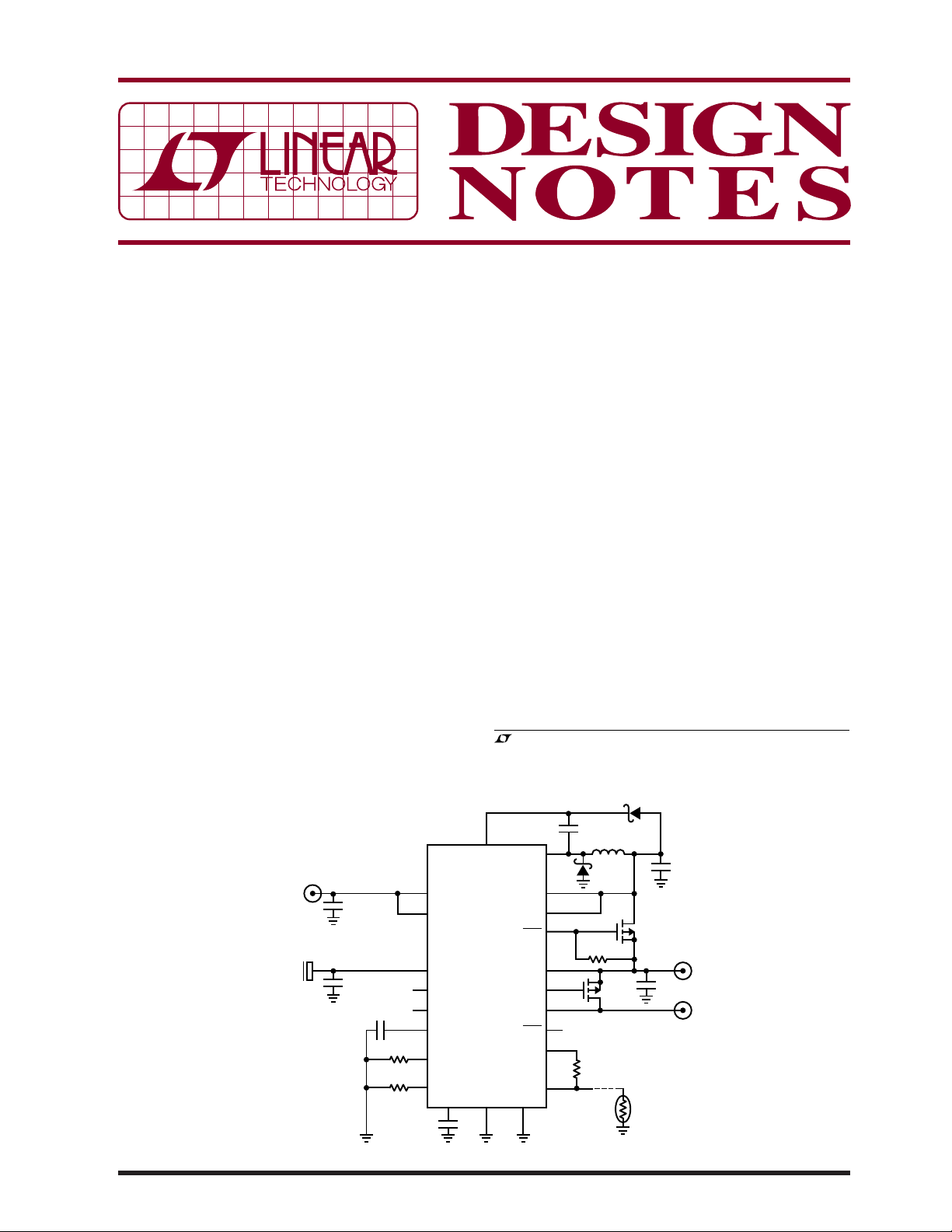
The LTC
4089 and LTC4089-5 (see Figure 1) conveniently integrate a high voltage and wide input range
(6V to 36V with 40V absolute maximum) monolithic
1.2A buck switching regulator and a USB power manager/charger into a compact thermally enhanced
BOOST
C4
0.15µF
R3
2.1k
R4
71.5k
21
22
12
15
16
17
14
9
C10
10pF
HVIN
HVEN
IN
HPWR
SUSP
TIMER
CLPROG
PROG
V
C
LTC4089EDJC
4
08/06/395
HVIN
6V TO 36V
USB
4.35V TO 5.5V
C1
1µF
50V
C5
4.7µF
6.3V
Figure 1. The LTC4089 Schematic Illustrates Multiple Input Voltage Capability
3mm × 6mm DFN package. The LTC4089’s buck regula-
tor output voltage tracks the battery voltage to within
TM
300mV. This Bat-Track
feature minimizes overall power
dissipation. The LTC4089-5 has a fi xed 5V at OUT when
power is applied at HVIN. When power is supplied from
the USB port, the power manager ma ximizes the available
power to the system load; up to the full USB available
power of 2.5W. It automatically adjusts the Li-Ion battery
charge current with respect to the system load current
to maintain the total input current compliance within the
USB limits. The total solution size is less than 2cm
all components on one side of the PCB.
Adaptive High Voltage Buck Minimizes Total Power
Loss
The LTC4089’s buck conver ter output voltage V
the battery voltage V
, so that the battery can be charged quickly while
V
BAT
, LT, LTC and LTM are registered trademarks of Linear Technology Corporation.
Bat-Track is a trademark of Linear Technology Corporation.
All other trademarks are the property of their respective owners.
20
HVOUT
HVOUT
U1
GND GND
2
HVPR
OUT
GATE
BAT
CHRG
VNTC
NTC
1
SW
0.1µF
C2
19
3
18
7
13
10
11
8
6
5
L1
10µH
D1
R6
10k
Q2
(OPTIONAL)
R5
10k
1%
. It is always 0.3V higher than
BAT
D2
C3
22µF
6.3V
Q1
(TO SYSTEM LOAD)
R
NTC
10k
DN395 F01
C6
4.7µF
6.3V
OUT
Li-ION+
OUT
tracks
2
with
minimizing overall power dissipation. Figure 2 shows the
overall effi ciency at various input voltages, where the
total power dissipation is less than 1.1W. Furthermore,
if the battery is excessively discharged and V
too low, the minimum V
is 3.6V to ensure con t inuous
OUT
BAT
falls
system operation.
USB Power Manager Maximizes Power Available
to the System
In a traditional dual input device, the input charges the
battery and the system’s power is directly taken from
the battery. This creates a number of problems. One of
these is that the system’s available power is reduced
by the low-battery voltage when there is USB power
present. For example, when V
= 3.3V, the available
BAT
power to the system is only 1.65W while the USB itself
supplies 2.5W. The balance is dissipated as heat. The
LTC4089 successfully solves this problem by providing
an intermediate voltage V
100
V
= 3.5V
BAT
= 700mA
I
95
BAT
= 0
I
OUT
90
85
80
75
70
EFFICIENCY (%)
65
60
55
50
0
515
10
HIGH VOLTAGE INPUT (V)
Figure 2. The LTC4089 High Voltage Charger
Effi ciency and Total Power Loss
to power the system load.
OUT
1.5
1.4
1.3
1.2
1.1
1.0
0.9
35
DN395 F02
0.8
0.7
0.6
0.5
40
CHARGER EFFICIENCY
BUCK EFFICIENCY
TOTAL EFFICIENCY
TOTAL P
LOSS
20
30
25
TOTAL POWER LOSS (W)
This V
is independent of the battery voltage and equal
OUT
to the USB voltage, thus the full USB power is available
to the system load. Table 1 shows the advantages of the
LTC4089 power manager over the traditional dual input
confi guration.
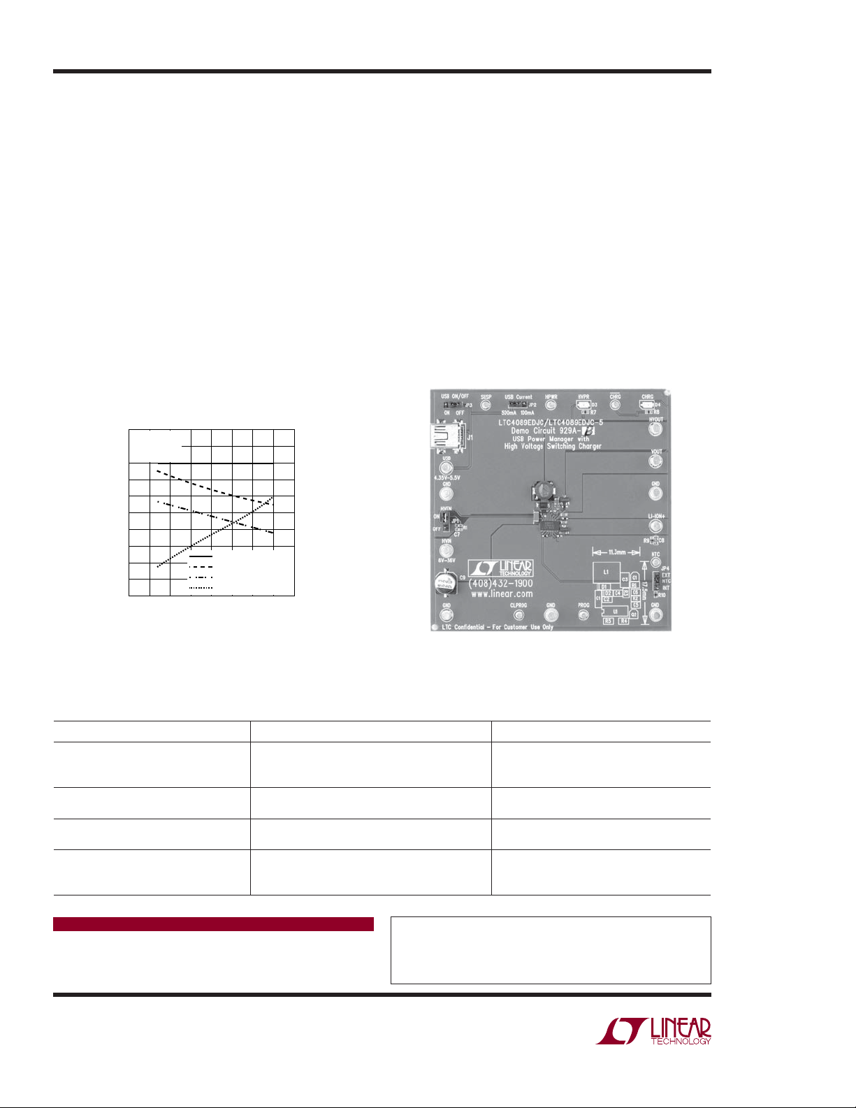
Small Footprint
With all the necessary components on the same side of
2
the PCB, the total solution size is less than 2cm
(11.3mm
× 17.5mm) as shown in Figure 3.
Summary
The LTC4089 integrates a high voltage wide input monolithic switching regulator, USB power manager and Li-Ion
battery charger into a 3mm × 6mm DFN package and
improves the functionality of USB-based and multiple
power input portable devices.
DN395 F03
Figure 3. The LTC4089 Demo Circuit with Layout in
Bottom Right Corner
Table 1. Comparison of Traditional Dual Input Charger and Linear Technology’s LTC4089 Power Manager/Charger for USB
Charging
SCENARIO TRADITIONAL DUAL INPUT CHARGER LTC4089 POWER MANAGER/CHARGER
Battery voltage is below trickle charging
voltage
Available current to system is only trickle charge
current (50mA to 100mA), which may not be
Full adapter/USB power is available to
system, although battery is in trickle charge
suffi cient to start the system
Battery is not present Most chargers consider this as a fault. The
system cannot start
= 3.3V at USB input Available power to system is only 1.65W. The
V
BAT
system power cannot be greater than this
System consuming close to the input
power limit
Cannot distinguish the available charging current.
Charger timer runs out before the battery is fully
charged
Data Sheet Download
http://www.linear.com
Full adapter/USB power is available to
system
Full 2.5W USB power is available to the
system
Charger time proportionally increases with
less available charge current. The battery is
always fully charged
For applications help,
call (408) 432-1900, Ext. 2364
Linear Technology Corporation
dn395f LT 0806 305K • PRINTED IN THE USA
1630 McCarthy Blvd., Milpitas, CA 95035-7417
●
(408) 432-1900
FAX: (408) 434-0507 ● www.linear.com
© LINEAR TECHNOLOGY CORPORATION 2006
 Loading...