

Switching USB Power Manager with PowerPath Control Offers
Fastest Charge Time with Lowest Heat – Design Note 415
Dave Simmons
Introduction
Lithium-Ion and Lithium Polymer batteries are common
in portable consumer products because of their relatively
high energy density—they provide more capacity than
other available chemistries within given size and weight
constraints. USB battery charging is also becoming
commonplace, as many portable devices require frequent
interfacing with a PC for data transfer.
A s p o r t a b l e pr o d u c t s b e c o me m o r e c o m p le x , t h e n e e d f o r
higher capacit y batteries increases, with a corresponding
need for more adv anced batter y chargers. Lar ger batteries
require either higher charging current or additional time
to charge to their full capacity. Most consumers look for
shorter charge times, so increasing the charge current
seems obviously pre ferable, but increasing charge curren t
presents two major problems. First, with a linear charger,
increased current creates additional power dissipation
(i.e., heat). Second, the charger must limit the current
drawn from the 5V USB bus to either 100mA (500mW)
or 500mA (2.5W) depending on the mode that the host
controller has negotiated.
TO USB
OR WALL
ADAPTER
V
BUS
11
/N
I
SWITCH
PWM AND
GATE DRIVE
PowerPathTM Controllers Deliver More Power to the
System Load
There are two methods commonly used to extract power
from a USB port. The fi rst method uses a current limited
battery charger directly between the USB port and the
battery. This is referred to as a Battery Fed System
because the system load is powered directly from the
• V
battery. Available power is given by I
is the only volt age available to the system load. When
V
BAT
USB
because
BAT
the battery is low, nearly half of the available power can
be lost within the linear battery charger element. In low
battery voltage protection mode, as little as 5% of the
available power may be usable.
The second method develops an intermediate voltage
between the USB port and the battery. This intermediate voltage bus topology is referred to as a PowerPath
System. In PowerPath ICs, a current limited switch is
placed between the USB port and the intermediate volt-
, LT, LTC, LTM are registered trademarks of Linear Technology Corporation.
PowerPath is a trademark of Linear Technology Corporation.
All other trademarks are the property of their respective owners.
SW
12
V
OUT
10
SYSTEM LOAD
3.5V TO (BAT + 0.3V)
05/07/415
2
CLPROG
–
+
1.188V 3.6V
AVERAGE INPUT
CURRENT LIMIT
CONTROLLER
AVERAGE OUTPUT
VOLTAGE LIMIT
CONTROLLER
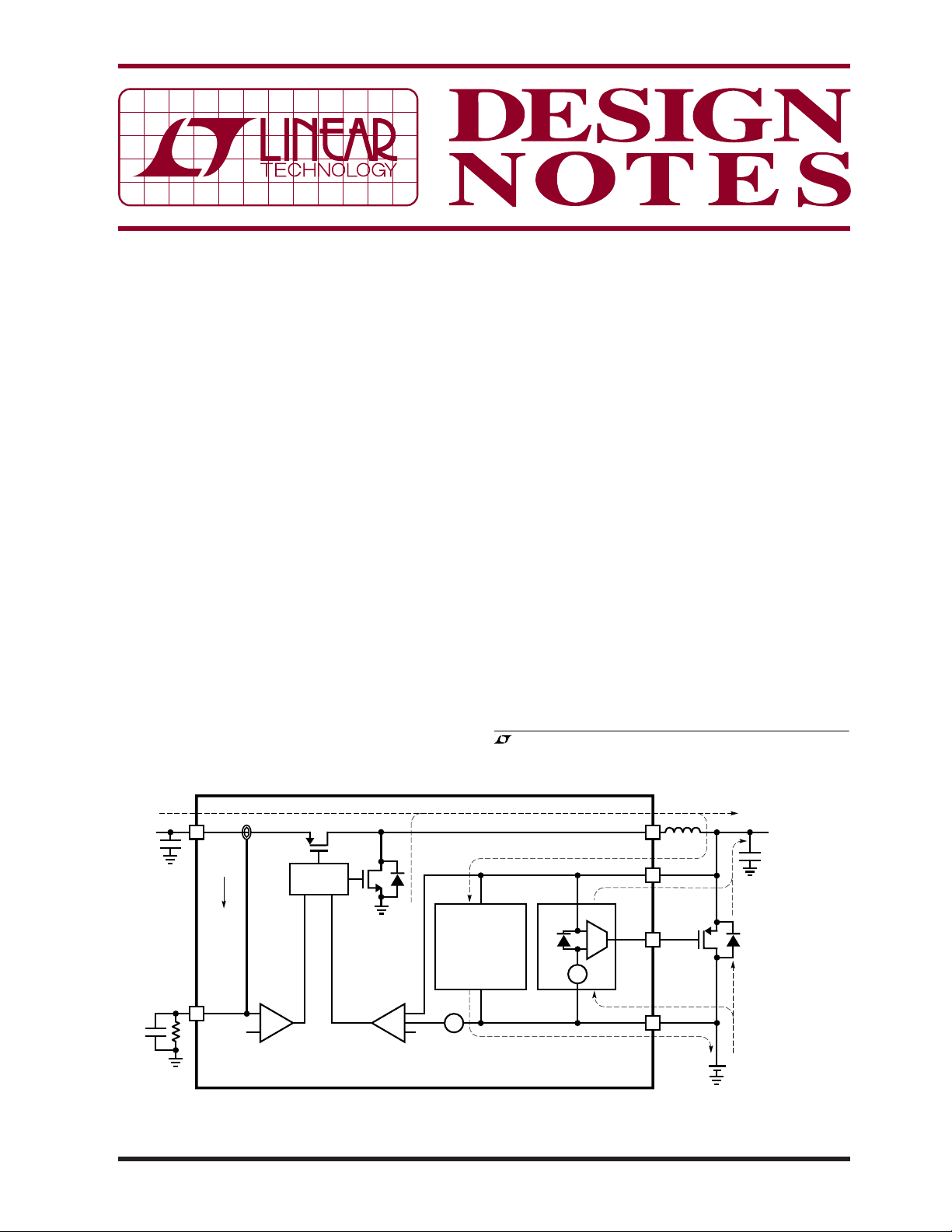
Figure 1. LTC4088 PowerPath Topology
–
+
+
CONSTANT CURRENT
CONSTANT VOLTAGE
BATTERY CHARGER
0.3V
+
–
IDEAL
DIODE
0V
15mV
OPTIONAL
+
EXTERNAL
IDEAL DIODE
PMOS
SINGLE CELL
Li-Ion
+
GATE
BAT
8
9
DN415 F01
–
–
+
age. The intermediate voltage, V
, then powers both
OUT
a linear battery charger as well as the entire portable
product. By using the intermediate voltage bus topology,
the battery is decoupled from the system load and charging can be carried out opportunistically. During charging
with a PowerPath system, the full 2.5W from the USB
port is made available to the system load as long as the
input current limit has not been exceeded. In this case
is just under the input voltage (5V for example).
V
OUT
However, since the battery voltage is much lower than
the 5V input, signifi cant power is still lost to the linear
battery charger element.
LTC4088 Makes Charging More Effi cient
The LTC®4088 replaces the current limited switch in traditional PowerPath systems with a 2.25MHz buck mode
synchronous switching regulator, as shown in Figure 1.
The intermediate voltage, V
, is regulated to just above
OUT
the battery voltage. Because power is conserved in a
switching regulator, the available output current is higher
than the input current.
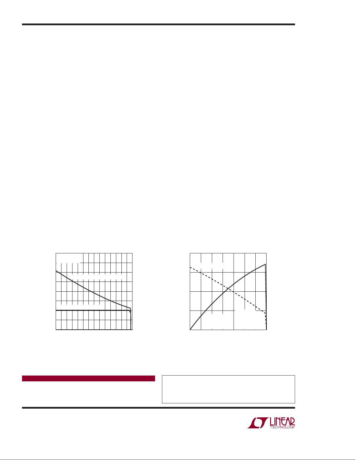
LTC4088 Reduces USB Charge Time
This additional current can be used to power the portable
product and charge the battery more quickly. Figure 2
shows the typical improvement in char ge current versus a
linear charger when powered from a 500mA USB port.
LTC4088 Eases Thermal Constraints
The second benefi t of the switching regulator is heat
reduction. Power lost by ineffi cient charging can cause
0.80
V
= 5V
BUS
= 500mA
I
BUS
0.75
0.70
0.65
0.60
CURRENT (A)
0.55
0.50
0.45
0.40
2.8
SWITCHING CHARGE CURRENT
LINEAR CHARGE CURRENT
3.0 3.2 3.6
3.4
V
BAT
3.8 4.0 4.2
DN415 F02
the external case of a portable product to become uncomfortably warm, and in extreme cases, it can cause
thermal limiting of the battery charger. Figure 3 shows
the typical effi ciency and power savings of the LTC4088
relative to a linear charger when connected to a 500mA
USB port.
The LTC4088 also includes a mode designed for use with
AC powered wall adapters, in which the maximum input
current is limited to 1A. Available current to the system
load and battery charger ranges somewhere between 1A
and 1.8A, depending on the battery voltage. Many higher
capacity batteries are capable of charging at these higher
rates, but with a volt or more difference between the wall
adapter and the battery, the accompanying dissipative
heating cannot be tolerated. Until now, these applications
simply had to settle for a lower than optimal charge rate,
and accompanying longer charge time.
Conclusion
The LTC4088 offers a dramatic advancement in battery
charging and power path management technology, with
its reduction in both heat generation and battery charge
time. Designed specifi cally for portable applications, its
high switching frequency and internal compensation
require only a small inductor and output capacitor. Only
the LTC4088’s unique topology of a buck mode switching
regulator working in tandem with a linear battery charger
can give this unparalleled performance.
92
POWER SAVED (W)
90
88
86
BATTERY CHARGE EFFICIENCY (%)
84
BATTERY
CHARGE
EFFICIENCY (%)
2.8
3.0 3.2 3.4 3.6
BAT (V)
V
= 5V
BUS
500mA MODE
= 2.94k
R
CLPROG
= 1k
R
PROG
3.8 4.0 4.2
DN415 F03
0.8
0.6
POWER SAVED (W)
0.4
0.2
0
Figure 2. Typical Charge Current for LTC4088 vs
Linear Charger When Powered from a 500mA USB Port
Data Sheet Download
www.linear.com
Linear Technology Corporation
1630 McCarthy Blvd., Milpitas, CA 95035-7417
●
(408) 432-1900
FAX: (408) 434-0507 ● www.linear.com
Figure 3. Battery Charger Effi ciency and
Power Savings Relative to a Linear
Charger When Charging from a USB Port
For applications help,
call (408) 432-1900, Ext. 2364
dn415f LT/TP 0507 409K • PRINTED IN THE USA
© LINEAR TECHNOLOGY CORPORATION 2007
 Loading...