


advertisement
Fast, High Effi ciency, Standalone NiMH/NiCd Battery Charging
Design Note 380
Fran Hoffart
Introduction
Although recent popular attention is focused on Lithium
Ion batteries, one must not forget that other battery
chemistries, such as Nickel Cadmium (NiCd) and Nickel
Metal Hydride (NiMH) have advantages in rechargeable
power systems. Nickel- based batteri es are robust, capable
of high discharge rates, have good cycle life, do not
require special protection cir cuitry and are less ex pensive
than Li-Ion. Among the two, NiMH batteries are rapidly
replacing NiCd because of their higher capacity (40% to
50% more) and the environmental concerns of the toxic
cadmium contained in NiCd batteries.
®
The LTC
4010 and LTC4011 are NiCd/NiMH battery
chargers that simplify Nickel-based battery charger
design and include power control and charge termination
for fast charging up to 16 series-connected cells using a
synchronous buck topology. The LTC4011 provides a full
feature se t in a 20-lead TSSOP while t he LTC4010 comes in
a 16-lead TSSOP. The LTC4010 removes the PowerPath
TM
control output, top-off charge indicator, DC power sense
input and provides limited thermistor options.
49.9k
(1.5 HRS)
0.1mF
Q3A
18
V
CC
20
INFET
2
FAULT
3
CHRG
13
TOC
19
READY
1
DCIN
10
TIMER
4
CHEM
5
GND
14
INTV
DD
LTC4011
21 (BACKSIDE)
TGATE
BGATE
SENSE
V
9V to 30V
V
IN
CHEM PIN
NiMH NiCd
Q1: FDC658P
Q2: Si3434DV
Q3: FDR8508P
LEDS
3k 3k 3k 3k
2Ok
3.3V
Figure 1. Full Featured Standalone 2A, 4-Cell NiMH Fast Charger with PowerPath Control
NiCd/NiMH Battery Charging Basics
Batteries come in many sizes and capacity ratings.
When specifying charge current, it is commonly related
to a battery’s capacity, or simply “C”. The letter “C” is a
term used to indicate the manufacturers’ stated battery
discharge capacity which is measured in milliamp-hours
(mAh). This capacity rating becomes important when
fast charging because it determines the required charge
current for proper charge termination.
There are several commonly used methods for charging
Nickel batteries. They are all related to the length of the
charge cycle which determines the recommended charge
current. A slow charge (or low rate charge) consists of a
relatively low charge current, typically 0.1C, applied for
approximately 14 hours set by a timer. A quick charge
applies a constant current of approximately 0.3C to the
battery while a fast charge applies a constant current of
1C or higher. Both quick and fast charge cycles require
that the charge current terminate when the battery
becomes fully charged.
, LTC and LT are registered trademarks and PowerPath is a trademark of Linear
Technology Corporation. All other trademarks are the property of their respective
PGND
BAT
V
CELL
V
CDIV
V
TEMP
owners.
RT
100k
17
15
16
11
12
30.1k
(4 CELLS)
8
10k
9
6
9.76k
7
10k
0.1mF
0.1mF
10mF
Q1
Q2
1A
28k
10mH
I
VIN
18V
I
BATT
R
SENSE
0.05
(2A)
10mF
NTC MURATA NCP18XH
Q3B
+
0603 SIZE
TO
SYSTEM
LOAD
I
DISCHARGE
2000mAh
NiMH
(4 CELLS)
NTC
10k
DN380 F01
01/06/380
During a fast charge cycle, a constant current is applied
to the battery while allowing the battery voltage to rise
to the level required (within limits) to force this current.
As the battery accepts charge, the battery voltage and
temperature slowly rise. As the battery approaches full
charge, the voltage rises faster, reaches a peak, then
begins to drop (–ΔV); at the same time, the battery
temperature begins to quickly rise (ΔT/Δt). Most fast or
quick charge termination methods use one or both of
these conditions to end the charge cycle.
Complete 4-Cell NiMH Battery Charger
Figure 1 shows a fast, 2A charger featuring the
high effi ciency LTC4011 550kHz synchronous buck
converter. The LTC4011 simplifi es charger design by
integrating all of the features needed to charge Ni-based
batteries, including constant current control circuitry,
charge termination, automatic trickle and top off
charge, automatic recharge, programmable timer,
PowerPath control and multiple status outputs. Such a
high level of integration lowers the component count,
enabling a complete charger to occupy less than 4cm
2
of board area.
Initial battery qualifi cation verifi es that suffi cient input
voltage is pres ent for charging and that the bat tery voltage
and battery temperature are within an acceptable range
before charging at full current. For deeply discharged
batteries, a low current trickle charge is applied to raise
the bat tery voltage to an appropr iate level before applying
full charge current. When qualifi cation is complete, the
full programmed constant-current begins.
Standalone Charge Termination
The charge termination methods used by the LTC4010
and LTC4011 utilize battery voltage and battery
temperature changes to reliably indicate when full
charge is reached as a function of the charge current
selected. The charge current must be suffi ciently high
(between 0.5C and 2C) for the battery to exhibit the
voltage and temperature profi le required for proper
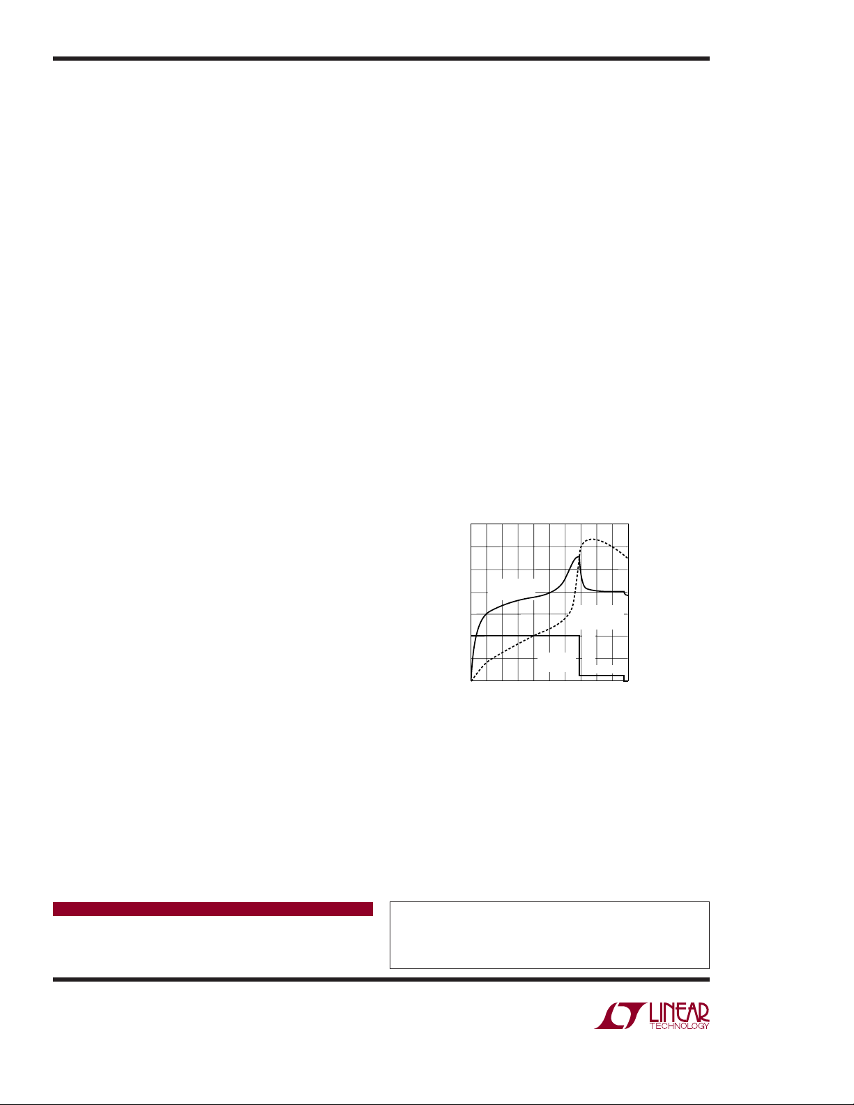
charge termination. Figure 2 shows a typical fast-charge
profi le displaying charge current, battery temperature
and per cell voltage. This profi le indicates that the charge
cycle terminated due to the rate of temperature rise
or ΔT/Δt.
The –ΔV charge termination algorithm begins shortly
after the full charge current starts fl owing. A fi xed delay
time prevents false termination due to battery voltage
fl uctuations from batteries that are deeply discharged
or haven’t been charged recently. For batteries that are
near full charge, the –ΔV termination sequence begins
immediately to prevent overcharging.
During the charge cycle, both the –ΔV and ΔT/Δt
termination methods are active. For NiMH batteries,
the –ΔV termination requires that the single cell battery
voltage drop 10mV from the peak voltage or the rateof-temperature rise (ΔT/Δt) be greater than 1°C/minute.
The measurements are taken every 30 seconds and the
results must be consistent for four measurements for
termination to take place. Typically the ΔT/Δt termination
method occurs earlier in the charge cycle. If this occurs,
the LTC4010/4011 adds a top-off charge at a reduced
charge current for 1/3 of the programmed time. Top-off
only occurs when charging NiMH batteries.
After the charge cycle has ended, the charger continues
monitoring the bat tery voltage. If the voltage drops below
a fi xed threshold level, due to an external load on the battery or self-discharge, a new charge cycle begins with the
charge termination algorithms immediately enabled.
1.60
1.55
1.50
)
V( E
SINGLE CELL
G
ATL
O
V LLE
C
1.45
1.40
1.35
1.30
1.25
VOLTAGE
BATTERY
TEMPERATURE
2A
CURRENT
CHARGE
0
40
20
TIME (MIN)
1A
60 80
Figure 2. Typical NiMH Fast Charge Profi le
TOP-OFF
100
DN380 • F02
42
40
( ERUTAREPMET YRETTAB ° )C
38
36
34
32
30
28
Conclusion
The LTC4010 and LTC4011 provide complete standalone
solutions for reliable, robust and safe fast charging of
NiCd and NiMH batteries. Proper charging is critical to
not only obtain maximum battery capacity but to also
avoid high temperatur es, overcharge and other conditions
which adversely affect battery life.
Data Sheet Download
http://www.linear.com
Linear Technology Corporation
1630 McCarthy Blvd., Milpitas, CA 95035-7417
(408) 432-1900
●
FAX: (408) 434-0507 ● www.linear.com
For applications help,
call (408) 432-1900, Ext. 2364
dn380 LT/TP 0106 409K • PRINTED IN THE USA
© LINEAR TECHNOLOGY CORPORATION 2006
 Loading...