

Dual Controller Provides 2µs Step Response and 92% Efficiency
for 1.5V Rails
Design Note 1028
Mike Shriver
Introduction
T he LTC®3838 is a dual ou tput, dual phase buck cont roller
that employs a contr olled constant on-time, vall ey current
mode architecture to provide fast load step response,
high switching frequency and low duty cycle capability.
The switching frequency range is 200kHz to 2MHz—its
phase-locked loop keeps the frequency constant during
steady-state operation and can be synchronized to an
external clock. The LTC3838 accepts a wide input range,
4.5V to 38V, and can produce 0.6V to 5.5V outputs.
V
IN
4.5V TO 14V
V
OUT1
1.2V
25A
C
OUT1
100µF
×2
+
C
180µF
+
C
OUT2
330µF
×3
C
L1
0.4µH
22µF
×4
2.21k
IN2
MT1
MB1
2.2Ω
1µF
V
IN
SENSE1
0.22µF
7.5k
0.1µF
2.2Ω
1µF
10k 15k
100k
47pF
18.2k
SENSE1
BOOST1
TG1
DB1
SW1
DRV
CC1
INTV
CC
4.7µF
BG1 BG2
PGND
V
OUTSENSE1
10k 10k
V
OUTSENSE1
PGOOD1 PGOOD2
PGOOD1 PGOOD2
0.01µF
TRACK/SS1
ITH1
470pF
DTR1
V
RNG1
137k
RT
SGND
RUN1
IN1
The remotely sensed V
has a voltage regulation ac-
OUT1
curacy of 0.67%, from 0°C to 85°C, even with a voltage
difference of ±0.5V between local ground and remote
ground. The current sense comparators are designed to
sense the inductor current with either a sense resistor
for high accuracy or with the inductor DCR directly for
reduced power losses and circuit size.
L, LT, LTC, LTM, Linear Technology, the Linear logo and PolyPhase are registered
trademarks of Linear Technology Corporation. All other trademarks are the property
of their respective owners.
LTC3838
–
+
SENSE2
SENSE2
BOOST2
TG2
SW2
DRV
EXTV
+
V
–
TRACK/SS2
ITH2
DTR2
V
RNG2
PHASMD
MODE/PLLIN
CLKOUT
RUN2
–
0.22µF
100k
47pF
40.2k
0.1µF
DB2
7.5k
2.21k
MT2
MB2
DN1028 F01
L2
0.4µH
C
OUT3
330µF
C
: SANYO 16SVP180MX
IN1
: MURATA GRM32ER61C226K
C
IN2
, C
: SANYO 2R5TPE330M9
C
OUT2
OUT3
, C
: MURATA GRM31CR60J107ME39L
C
OUT1
OUT4
DB1, DB2: CENTRAL CMDSH-3
L1, L2: VISHAY IHLP5050FDER0R4M01
MT1, MT2: INFINEON BSC050NE2LS
MB1, MB2: INFINEON BSC010NE2LS
+
C
OUT4
100µF
×2
×3
+
CC2
CC
FB2
0.01µF
220pF
300kHz
V
1.5V
25A
OUT2
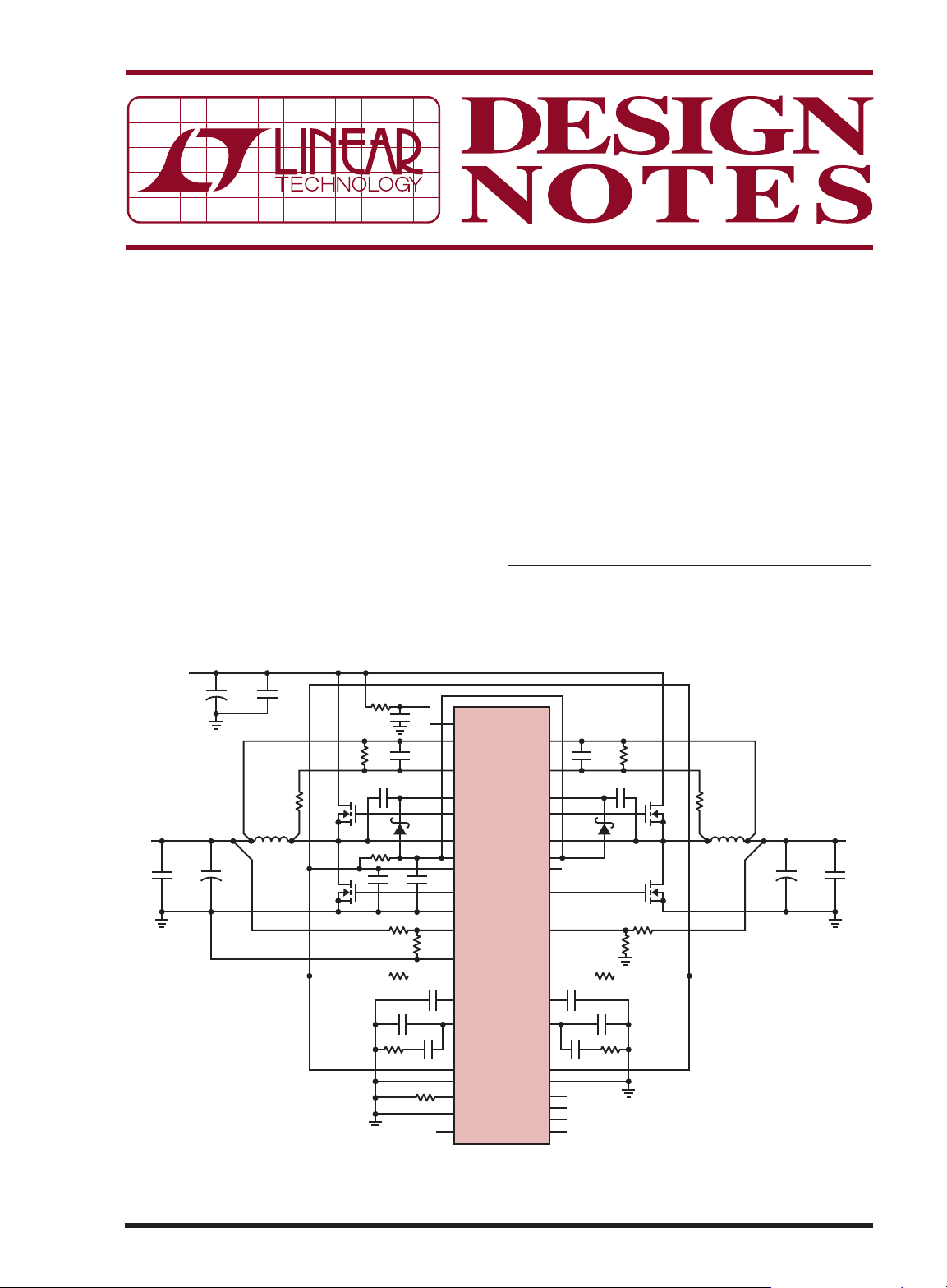
Figure 1. Dual Output, 1.5V/25A and 1.2V/25A Buck Converter Operating at FSW = 300kHz
1.5V/25A and 1.2V/25A Buck Converter
Figure 1 shows a dual 25A output buck converter synchronized to an external 300kHz clock. The controlled
constan t on-time valley current mode architec ture allows
the switch node pulses to temporarily compress when a
5A to 25A load step is applied to the 1.2V rail, resulting
in a voltage undershoot of only 58mV (see Figure 2).
The full load efficiency for the 1.5V and 1.2V rails is
91.8% and 90.8%, respectively, as shown in Figure 3.
The high efficiency is realized by the strong gate drivers,
optimized dead time and DCR sensing.
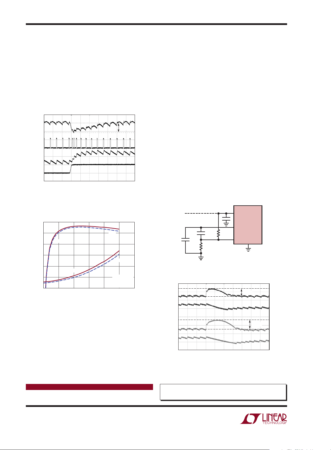
V
O(AC)
50mV/DIV
VSW
10V/DIV
20A/DIV
LOAD STEP
20A/DIV
IL
25A
5A
5µs/DIV
58mV
DN1028 F02
Figure 2. 20% to 100% Step Load Response of the
1.2V Rail at VIN = 12V, FSW = 300kHz, Mode = FCM
= 300kHz
DN1028 F03
6
5
POWER LOSS (W)
4
3
2
1
0
95
90
85
80
EFFICIENCY
75
70
65
EFFICIENCY
POWER LOSS
151050 20 25 30
LOAD CURRENT (A)
1.5V
1.2V
1.5V
1.2V
V
= 12V
IN
F
SW
MODE = CCM
Figure 3. Efficiency and Power Loss of the 1.5V/25A
and 1.2V/25A Converter
The two channels operate 180° out-of-phase, which
permits the use of fewer input capacitors due to input
capacitor ripple current cancellation. For higher current
applications, t wo or more phases can be tied to gether to
form a single output, P olyPhase
®
converter. The benefits
include a faster load step response, reduced input and
output capacitance and reduced thermal dissipation.
Detect Transient Feature Further Speeds Up
Transient Response
An innovative feature of the LTC3838 is the load release
transient detect feature. The DTR pin indirectly monitors the output voltage by looking at the AC-coupled
ITH signal. If the inferred overshoot exceeds a user
set value, the bottom FET turns off. This allows the
inductor current to slew down at a faster rate, which
in turn reduces the overshoot. Per Figure 4, a 32%
reduction in the overshoot is realized on the 1.2V rail.
Greater improvements occur at lower output voltages.
Conclusion
The LTC3838 is a dual output buck controller ideal for
applications that require a fast load step response, high
switching fre quency, high ef ficiency and accurate ou tput
voltages. Other features include selectable operating
modes: forced continuous mode (FCM) for fixed frequency operation or discontinuous mode (DCM) for
higher efficiency at light load, programmable current
limit thresholds, soft-start, rail tracking and individual
PGOOD and RUN pins. The LTC3838 comes in a 5mm
× 7mm QFN package or a thermally enhanced 38-lead
TSSOP package.
LTC3838
INTV
CC
ITH1
34.8k470pF
5µs/DIV
DTR1
90mV
DN1028 F04a
119mV
DN1028 F04
WITH
DTR
ORIGINAL
CIRCUIT
47pF
38.3k
Figure 4a. Implementation of the Detect Transient
Feature on the 1.2V Rail
V
O(AC)
100mV/DIV
IL
50A/DIV
V
O(AC)
100mV/DIV
IL
50A/DIV
Figure 4b. 100% to 20% Step Load Response of the
1.2V Rail with and without the Detect Transient Feature,
VIN = 12V, FSW = 300kHz, Mode = FCM
Data Sheet Download
www.linear.com
Linear Technology Corporation
1630 McCarthy Blvd., Milpitas, CA 95035-7417
(408) 432-1900
●
FAX: (408) 434-0507 ● www.linear.com
For applications help,
call (408) 432-1900, Ext. 3720
dn1028 LT 0312 • PRINTED IN THE USA
LINEAR TECHNOLOGY CORPORATION 2012
 Loading...