

Multiphase DC/DC Controller Pushes Accuracy and Bandwidth
Limits
Design Note 434
Tick Houk
Introduction
Speed and accuracy don’t always go hand-in-hand
in DC/DC converter systems—that is, until now. The
LTC3811 is a dual output, fi xed frequency current mode
DC/DC switching regulator controller designed for one of
today’s most demanding power supply applications: high
current, low voltage processor core supplies.
With supply current requirements in excess of 100A
and supply voltages as low as 1V, every milliohm of
PCB resistance and every millivolt of IR drop count. The
LTC3811 has an output voltage tolerance of ±0.5% over
temperature, giving power supply designers unprecedented fl exibility when making component value and
board layout choices.
0.1μF
BAT54
V
OUT1
15A
1.21k
56k
EXTV
TG1
BOOST1
SW1
BG1
CLKOUT
PLL/LPF
MODE/SYNC
PHASMODE
SENSE1
SENSE1
RNG2
RNG1
RUN2
RUN1
FB1
COMP1
SS/TRACK1 SS/TRACK2SGND
RJK0305DPB
RJK0301DPB
1.21k 1.21k
0.5mΩ
2V
330μF
47μF
×2
X5R
11.8k
1%
4.99k
1%
0.1μF
680nF 680nF0.4μH
33pF
100pF
INTV
V
IN
CC
LTC3811
+
–
5nF
In addition to high accuracy, the LTC3811’s low minimum on-time (typically 65ns) allows users to convert a
12V input to a 1V output at switching frequencies up to
750kHz, optimizing load transient response and reducing
the solution size.
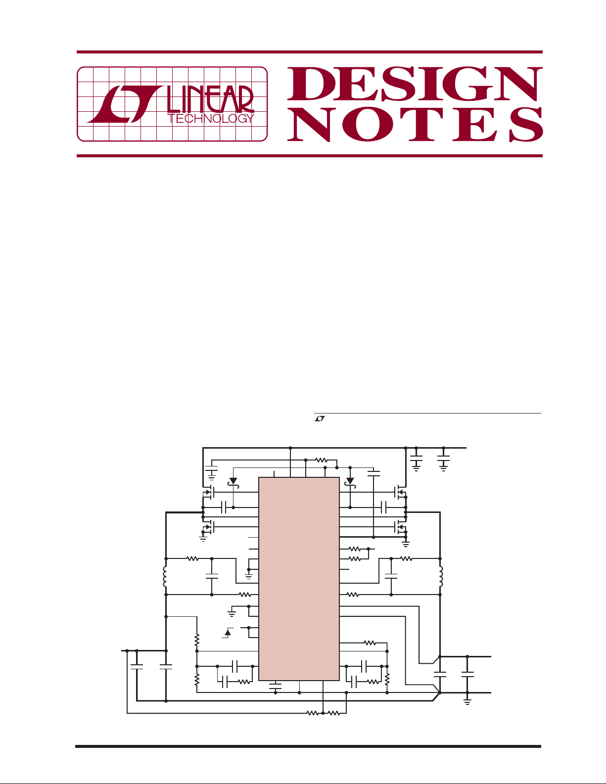
A Dual Output, 2-Phase Supply with Differential
Remote Sensing and Inductor DCR Sensing
Figure 1 illustr ates a dual output supply using the LTC3811.
The 1.5V, 15A output is regulated using the integrated
diff erential remote sense ampli fi er and tracks t he output of
channel 1 during star t-up. Both outputs use DCR sensing
in order to maximize effi ciency and operate 180° out of
, LT, LTC, LTM and PolyPhase are registered trademarks of Linear Technology
Corporation. All other trademarks are the property of their respective owners.
V
IN
47μF
X5R
330μF
16V
4.5V TO 14.5V
330μF
×2
DN434 F01
V
1.5V
15A
OUT2
1Ω
DRV
CC
CC
TG2
BOOST2
SW2
BG2
PGND
PGOOD1
PGOOD2
CS/OUT
SENSE2
SENSE2
DIFF/IN
DIFF/IN
DIFF/OUT
FB2
COMP2
2.43k 1.21k
47μF
10μF
X5R
BAT54
0.1μF
100k
INTV
CC
100k
+
1.21k
–
+
–
7.5k
1%
33pF
100pF
56k
4.99k
1%
X5R
RJK0305DPB
RJK0301DPB
0.4μH
0.5mΩ
02/08/434
Figure 1. Dual Output, 2-Phase Supply with Differential Remote Sensing and Inductor DCR Sensing
phase in order to reduce the size of the input capacitor.
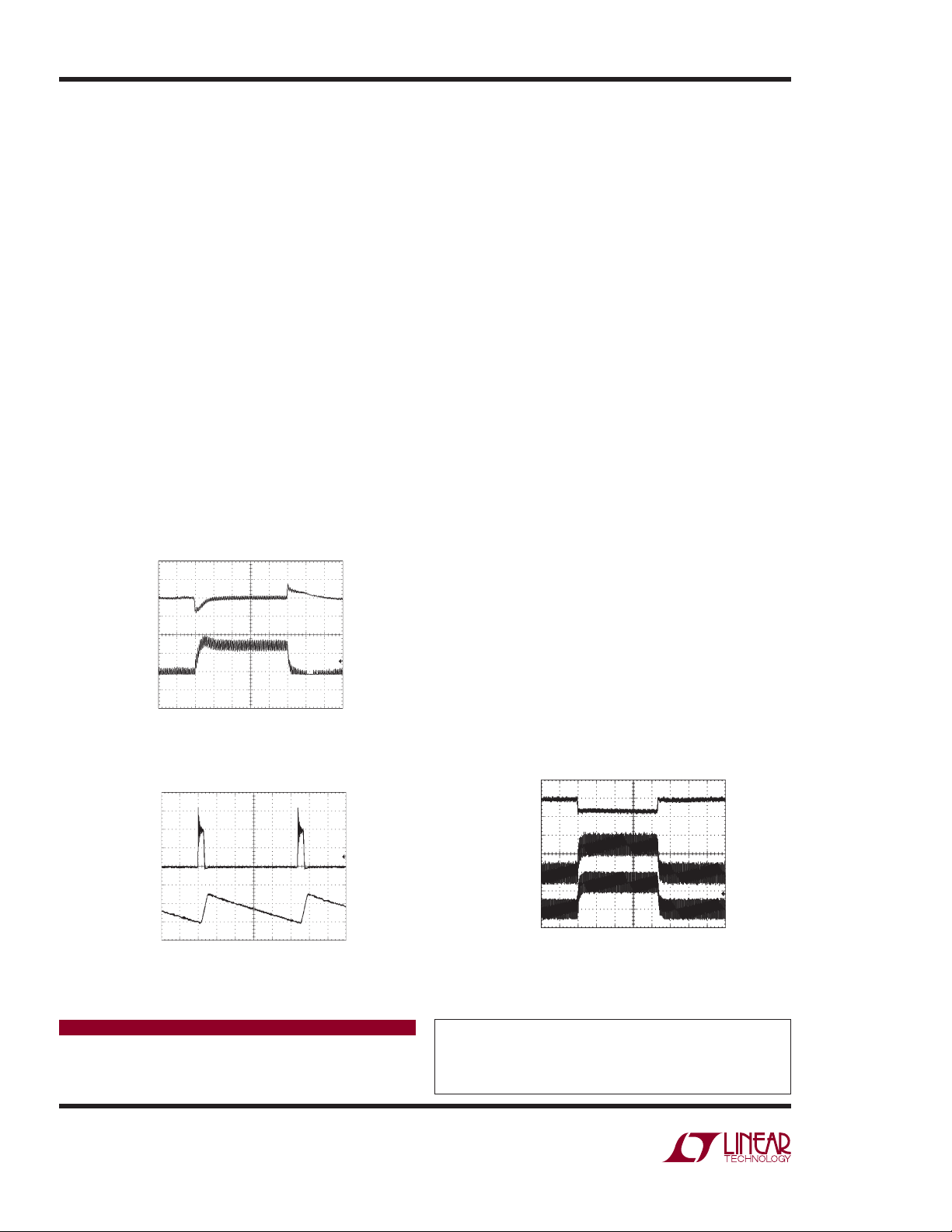
Figure 2 illustrates the load step response for channel 2.
Figure 3 illustrates low duty cycle waveforms for a 20V
input, 1.2V output application.
In order to accommodate the use of low DCR inductors
and still maintain good control over the maximum output
current, the current sense voltage for each channel is programmable from 24mV to 85mV using the RNG pins.
For noise-sensitive applications, where the switching
frequency needs to be synchronized to an external clock,
the LTC3811 contains a PLL with an input r ange of 150kHz
to 900kHz. In addition, the MODE/SYNC, PHASEMODE
and CLKOUT pins allow multiple LTC3811s to be daisychained in order to produce a single high current output.
The LTC3811 can be confi gured for 2-, 3-, 4-, 6- or 12phase operation, extending the load current range to
beyond 200A.
A Tried-and-True Architecture
The fi xed frequency, peak current mode control architecture was chosen for its excellent channel-to-channel
current matching and its robust cycle-by-cycle current
limit. Current sensing can be done using either a resistor
in series with the inductor or by sensing the DCR of the
inductor with an RC fi lter. This gives the user a choice
between optimum control of the maximum inductor current and maximum effi ciency.
V
OUT
50mV/DIV
AC COUPLED
I
L
5A/DIV
VIN = 12V
= 1.5V
V
OUT
= 0.5A TO 8A
I
LOAD
20μs/DIV
Figure 2. Load Step Response
DN434 F02
The LTC3811 has a 4.5V to 30V input voltage range and
is available in two package options: a 38-pin 5mm × 7mm
QFN and a 36-pin SSOP.
Load Step Improvement with Voltage Positioning
For single-output multiphase applications, the LTC3811
contains an amplifi er for voltage positioning purposes.
The current sense input voltages are converted to
an output current by a multiple-input, single-output
transconductance amplifi er, so that an error voltage
proportional to the load current can be introduced at the
input of the differential amplifi er. This transconductance
amplifi er allows the user to program an output load
line, improving the DC and AC output accuracy in the
presence of load steps. Figure 4 illustrates the load step
response for a 2-phase, single output power supply using the LTC3811.
Conclusion
The LTC3811 is a vers atile, high performan ce synchronous
buck controller optimized for low voltage, high current
supply applications. With an output accuracy of ±0.5%
and a remote sensing differential amplifi er, it represents
a new benchmark for DC/DC converters. It can easily
be confi gured for either single- or dual-output supplies,
inductor DCR sensing or a sense resistor, and it takes
advantage o f Linear Technology’s propriet ary PolyPhase
®
current sharing architecture. The combination of a very
low minimum on-time and a fi xed frequency peak current
mode control archi tecture no longer force the power supply
designer to trade off performance for protection.
SW
10V/DIV
I
L
2A/DIV
VIN = 20V
V
= 1.2V
OUT
= 1.5A
I
LOAD
250ns/DIV
DN434 F03
Figure 3. LTC3811 Low Duty Cycle Waveforms
Data Sheet Download
www.linear.com
Linear Technology Corporation
1630 McCarthy Blvd., Milpitas, CA 95035-7417
(408) 432-1900
●
FAX: (408) 434-0507 ● www.linear.com
V
OUT
50mV/DIV
AC COUPLED
I
L1
5A/DIV
I
L2
5A/DIV
VIN = 12V
= 1.5V (2-PHASE)
V
OUT
= 0A TO 15A
I
LOAD
50μs/DIV
DN434 F04
Figure 4. Load Step Response for a 2-Phase, Single Output
Supply with Voltage Positioning (Forced Continuous)
For applications help,
call (408) 432-1900, Ext. 2134
dn434f LT/TP 0208 241K • PRINTED IN THE USA
© LINEAR TECHNOLOGY CORPORATION 2007
 Loading...