

advertisement
Low EMI Synchronous DC/DC Step-Down Controllers Offer
Programmable Output Tracking – Design Note 382
Charlie Zhao
Introduction
The LTC®3808 syn chronous DC/DC step- down controller
p a c k s n u m e r o u s f e a t u r e s r e q u ir e d b y t h e l a t e s t e l e c t r o n i c
devices into a low profi le (0.75mm) 3mm × 4mm leadless
DFN package or a leaded SSOP-16 package. Two similar
parts, the LTC3809 and LTC3809-1, are even smaller, but
less feature-rich versions of the LTC3808. The LTC3809
family is available in a 3mm × 3mm leadless DFN package
or a 10-pin MSOP Exposed Pad package. All three parts
can provide output voltages as low as 0.6V and output
currents as high as 7A from a 2.75V to 9.8V input range,
making them ideal devices for one or two lithium-ion cell
inputs as well as distributed DC power systems.
The LTC3808 and LTC3809 also include important
features for noise-sensitive applications, including a
phase-locked loop (PLL) for frequency synchronization
and spread spectrum frequency modulation to minimize
generated electromagnetic interference (EMI). The
adjustable oper ating frequency (300kH z to 750kHz) allows
the use of small surface mount inductors and ceramic
capacitors for compact power supply solutions.
Other features include:
• Low operating quiescent current to improve battery
life and light load effi ciency
™
• No R
SENSE
current mode technology which senses
the voltage across the main (top) power MOSFET to
improve effi ciency and reduce the size and cost of the
solution
• Current mode control for excellent AC and DC line and
load regulation
• Low dropout (100% duty cycle) for maximum energy
extraction from a battery source
• Output overvoltage protection and short circuit current
limit protection
• Adjustable or fi xed built-in soft-start timer
• Output voltage ramp control and the ability to track
other voltage sources (LTC3808 and LTC3809-1)
• PowerGood voltage monitor (LTC3808)
Table 1 compares the features of these three parts.
Table 1.
START-UP
CONTROL
Internal
LTC3808
External
Tracking
LTC3809 Internal Yes Yes No
Internal
LTC3809-1
External
Tracking
SPREAD
SPECTRUM
ADJUSTABLE
FREQ/PLL
Yes Yes Yes
No No No
POWER
GOOD
Three Choices for Start-Up Control
The start-up of V
for the LTC3808 and LTC3809-1 is
OUT
based on the three different connections to the TRACK/
SS pin. A typical application is shown in Figure 2. When
TRACK/SS is connected to V
, the start-up of V
IN
OUT
is
controlled by the internal soft-start which ramps from
0V to (V
) in about 1ms. A second start up mode
FB
allow s the 1ms sof t- st ar t t ime to i ncre as e or de crea se b y
, LTC and LT are registered trademarks and No R
Linear Technology Corporation. All other trademarks are the property of their
respective owners.
301k
220pF
1000pF
2200pF
10onF
88.7k
100pF
15k
2
SYNC/MODE V
1
PLLLPF
6
IPRG
LTC3808EDE
4
I
TH
TRACK/SS
3
V
FB
GND
59k
9
IN
8
TG
10
SW
7
BG
5
RUN
15
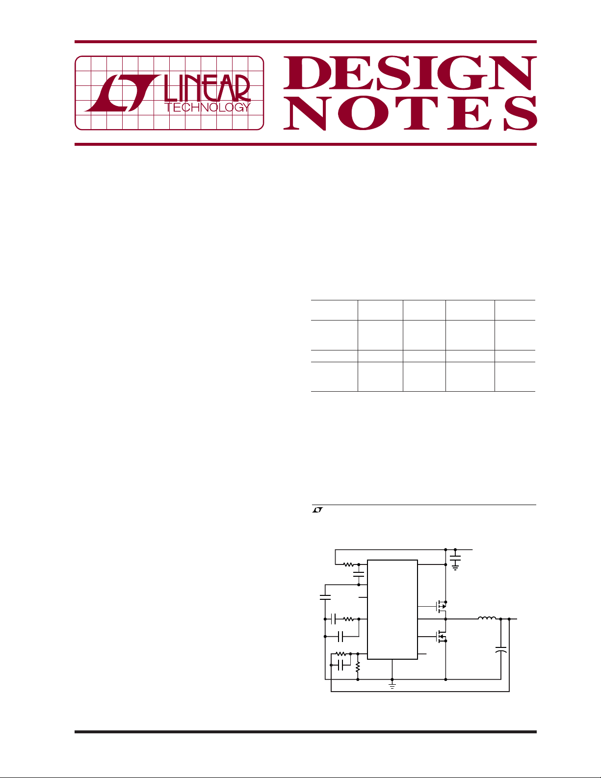
Figure 1. Synchronous Converter with Spread
Spectrum Frequency Modulation
is a trademark of
SENSE
V
IN
2.75V TO 9.8V
10µF
MP
Si4431BDY
MN
Si4860DY
L: VISHAY IHLP-2525CZ-01
1.5µH
C
150µF
L
OUT
+
DN382 F03
V
1.5V
I
OUT
2A
OUT
02/06/382
connectin g an external capa citor CSS betwe en the TRACK /
SS pin and ground. An internal 1μA current source and
the value of C
control the ramp time of TRACK /SS from
SS
0V to above 0.6V. In this case, the LTC3808 and
LTC3809-1 regulate the VFB to the voltage at the TRACK/
SS pin instead of the internal soft-start ramp. The third
mode allows V
track an external voltage, V
10nF
10k
1M
220pF
15k
1.18k
V
x
C
SS
10nF
118k
100pF
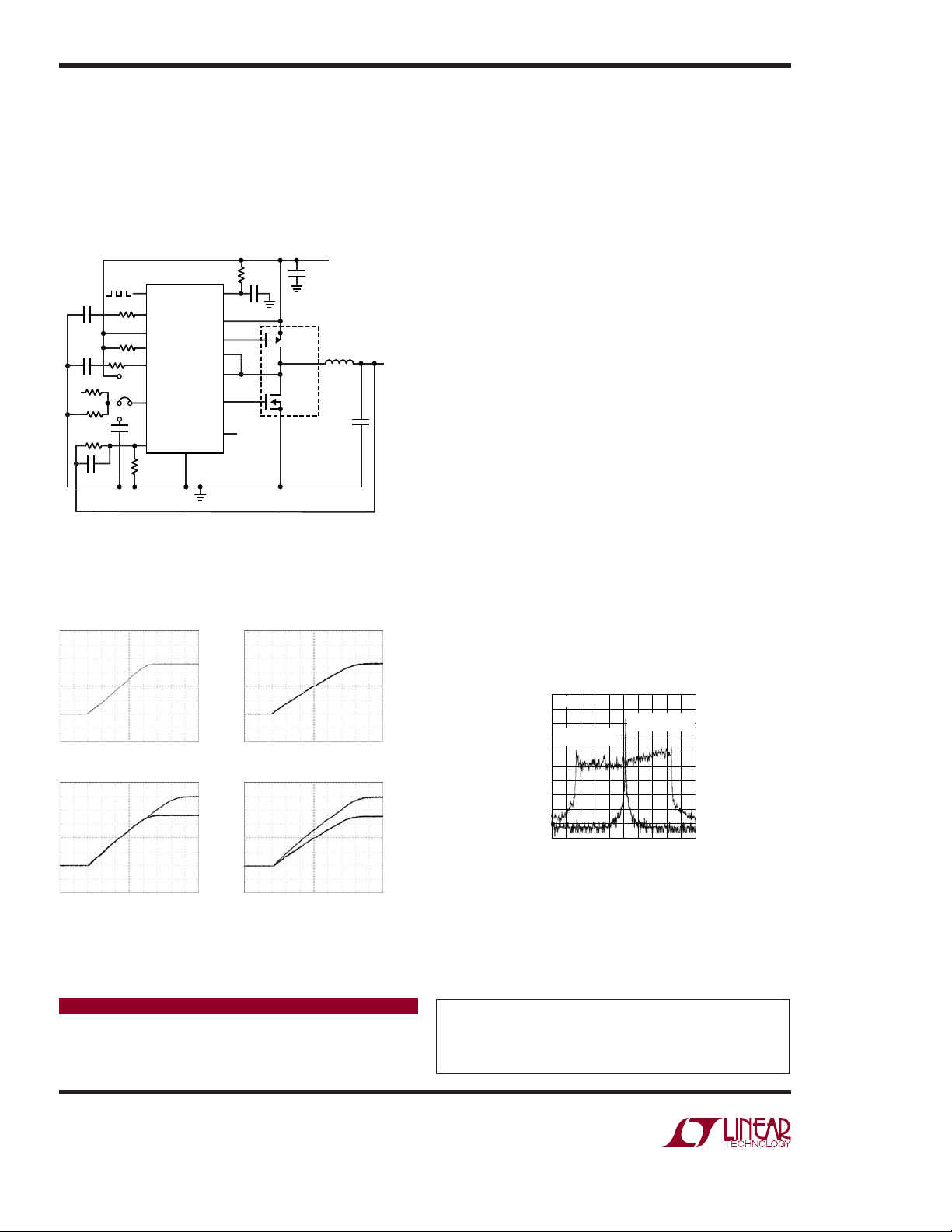
Figure 2. The LTC3808 Offers the Flexibility of Start-Up
Control Based on the Three Different Connections
on the TRACK/SS Pin
Start-Up with Internal Soft-Start
(TRACK/SS = V
= 4.2V
IN
R
LOAD
Start-Up with Coincidental Tracking Start-Up with Ratiometric Tracking
= 1Ω
)
IN
200µs/DIVV
of the LTC3808 and LTC3809-1 to
OUT
, during start-up if a resistor
X
2
SYNC/MODE V
1
PLLLPF
8
IPRG
4
PGOOD
6
I
TH
LTC3808EDE
3
TRACK/SS
5
V
FB
GND
59k
DN382 F02a
SENSE
SENSE
15
10Ω
1µF
12
IN
11
+
10
TG
13
–
14
SW
9
BG
7
RUN
Start-Up with External Soft-Start
(CSS = 10nF)
V
OUT
1.8V
500mV/DIV
= 4.2V
IN
R
LOAD
V
x
2.5V
V
OUT
1.8V
500mV/DIV
10µF
MP
Si7540DP
MN
Si7540DP
L: VISHAY IHLP-2525CZ-01
< V
V
OUT
1ms/DIVV
= 1Ω
x
V
IN
5V
1.5µH
C
150µF
L
OUT
V
OUT
1.8V
I
OUT
5A
X2
DN382 F01
V
OUT
1.8V
500mV/DIV
DN382 F02b
V
x
2.5V
V
OUT
1.8V
500mV/DIV
divider from V
3 shows the start-up of V
is connected to the TRACK /SS pin. Figure
X
in these tracking modes for
OUT
the circuit shown in Figure 2.
For simplicity, the LTC3809 only offers a 1ms internal
soft-start.
Low EMI DC/DC Conversion
The LTC3808 and LTC3809 minimize the need for EMI
shields and fi lters in applications such as navigation
systems, wireless LANs, data acquisition boards and industrial and military radio devices by optionally spreading
the nominal operating frequency (550kHz) over a range
of frequencies between 460kHz and 635kHz. Spread
spectrum frequency modulation is enabled by biasing
the SYNC/MODE pin to a DC voltage between 1.35V and
– 0.5V). An internal 2.6μA pull-down current source
(V
IN
at the SYNC/MODE pin can be used to set the DC voltage
at this pin by tying a resistor with an appropriate value
betw een SYNC/MODE and V
. Figure 1 shows the appli ca-
IN
tion circuit and Figur e 4 shows the frequency spectral plo ts
of the output (V
) with and without spread spectrum
OUT
modulation. Note the signifi cant reduction in peak output
noise (>20dBm) with spread spectrum enabled.
Conclusion
The LTC3808, LTC3809 and LTC3809-1 offer fl exibility,
high effi ciency, low EMI and many other popular features
in small thermally effi cient packages. They offer excellent
solutions for low voltage portable and distributed power
systems that require a small footprint, high effi ciency
and low noise.
RBW: 100Hz
SPREAD SPECTRUM
FREQUENCY (Hz)
DISABLED
DN382 F04
SPREAD SPECTRUM
ENABLED
NOISE (dBm)
–10dBm/DIV
400k 550k 700k
R
R
IN
TA
TB
= 4.2V
= 590Ω
= 1.18k
10ms/DIVV
DN382 F02c
= 4.2V
= 590Ω
= 1.69k
10ms/DIVV
IN
R
TA
R
TB
Figure 3. Start-Up Output Voltage Tracking Plots for
Circuit in Figure 2
Data Sheet Download
Data Sheet Download
Data Sheet Download
www.linear.com
Linear Technology Corporation
1630 McCarthy Blvd., Milpitas, CA 95035-7417
●
(408) 432-1900
FAX: (408) 434-0507 ● www.linear.com
DN382 F02d
Figure 4. Comparison of the V
Spectrum with and
OUT
without Spread Spectrum Modulation Enabled
For applications help,
call (408) 432-1900, Ext. 2759
dn382 LT/TP 0206 409K • PRINTED IN THE USA
© LINEAR TECHNOLOGY CORPORATION 2006
 Loading...