

advertisement
High Effi ciency 4-Switch Buck-Boost Controller Provides
Accurate Output Current Limit – Design Note 499
Tage Bjorklund
Introduction
A 4-switch buck-boost converter (Figure 1) is often a
bett er alternative to a transformer-based topology w hen
a converter’s input voltage can be above or below the
regulated output voltage and isolation is not required.
A buck-boost converter provides a wider input voltage
range, better effi ciency and has no need of a bulky
transformer. A buck-boost converter is much more
effi cient than a comparable SEPIC converter.
®
The LTC
3789 is a buck-boost switching regulator
controller that operates in current mode at a constant
switching frequency. Current mode control simplifi es
loop compensation and yields excellent load and line
transient response with only small output and input
c a p a c i t a n c e . F u r t h e r m o r e , a n a c c u r a t e i n d u c t o r c u r r e n t
limit allows use of a small size inductor.
LTC3789 Features
The internal oscillator can be programmed by a resistor, applied voltage, or phase-locked to an external
clock within a 200kHz to 600kHz frequency range. The
LTC3789’s wide 4V to 38V (40V maximum) input and
output range and seamless, low noise transitions between oper ating regions is ideal for automotive, tele com
and battery-powered systems. Higher input voltage is
easily enabled by adding a high voltage gate driver for
the input side MOSFETs, for example the LTC4444-5.
The LTC3789 includes two int ernal series regulator s that
provide 5.5V for gate dri vers and control circuitr y. During
start-up the current is drawn from V
rating), b ut switches to EX T V
CC
as soon as the voltage on EXTV
(40V maximum
IN
(14V maximum rating)
exceeds 4.8V, to
CC
decrease power loss.
This 4-switch topology allows the output to be disconnected from the input during shutdown. LTC3789
features adjust able soft-star t, no reverse current during
start-up and 1% output voltage accuracy.
L SW1
V
IN
C
A
IN
Figure 1. 4-Switch Buck-Boost Converter Using the
LTC3789
SW2
BC
SENSE
R
SENSE
SENSE
LTC3789
D
+
–
+
SENSE
–
SENSE
V
OUT
C
OUT
R1
R2
DN499 F01
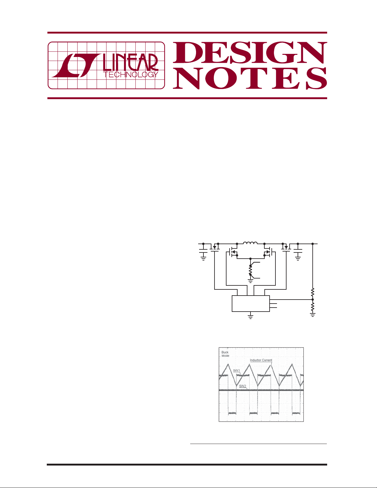
Figure 1 shows a simplifi ed schematic of a buck-boost
converter. The LTC3789 controls four ex ternal N-channel
MOSFETs (A, B, C, D). The power s tage uses one inductor
(L), and a current sense resistor (R
SENSE
) for current
mode control and inductor current limit. Figures 2
to 4 show the switch waveforms for buck, buck-boost,
and boost modes of operation.
The LTC3789 is available in low profi le 28-pin 4mm ×
5mm QFN and narrow SSOP packages.
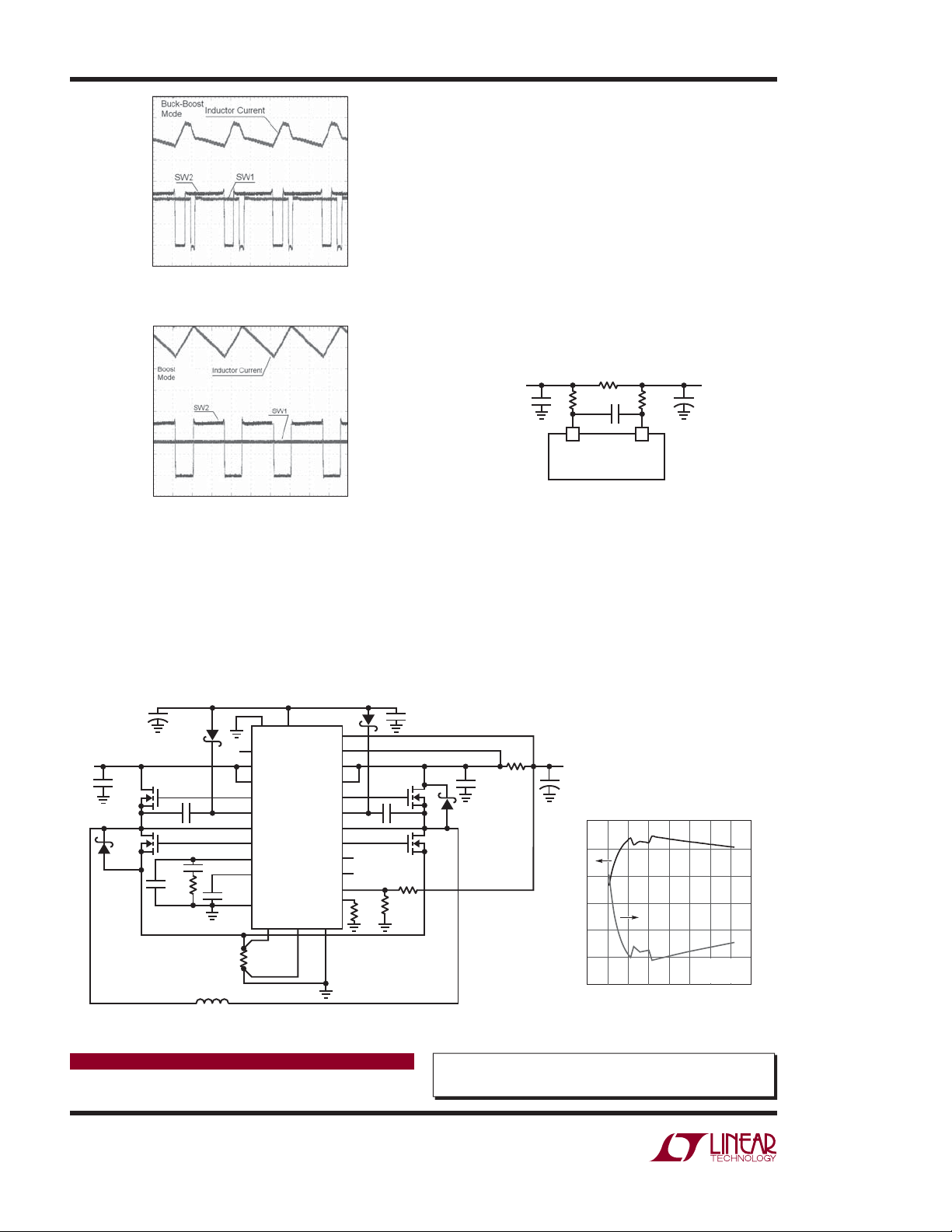
12V, 5A Output from a 4V to 38V Input
Figure 5 shows a buck-boost regulator that takes a 4V
to 38V input and converts it to a fi xed 12V.
01/12/499
5V/DIV
1A/DIV
5V/DIV
1μs/DIV
Figure 2. Buck Mode [VIN = 20V, V
L, LT, LTC, LTM, Linear Technology, the Linear logo are registered trademarks
of Linear Technology Corporation. All other trademarks are the property of their
respective owners.
DN499 F02
= 12V]
OUT
1A/DIV
5V/DIV
5V/DIV
1μs/DIV
Figure 3. Buck-Boost Mode [VIN = 11V, V
1A/DIV
5V/DIV
5V/DIV
1μs/DIV
Figure 4. Boost Mode [VIN = 8V, V
DN499 F03
DN499 F04
OUT
= 12V]
OUT
= 12V]
The MODE/PLLIN pin can be used to select between
pulse-skipping mode and forced continuous mode
operation, or allows the IC to be synchronized to an
external clock. Pulse-skipping mode offers the lowest
ripple at light loads, while forced continuous mode
operates at a constant frequency for noise-sensitive
applications.
A power good output pin (PGOOD) indicates when the
output is within 10% of its set point.
Accurate Output (or Input) Current Limit
The optional output current feedback loop shown in
Figure 6 provides support for ba ttery charging and other
constant curr ent applications, where an accurate ou tput
current limit is ess ential. The output curren t limit function
provides a constant current characteristic—the output
current is limited to a constant level even as the output
voltage is pulled down by an overcurrent condition.
Alternatively the sense resistor can simply be moved
to the input side to accurately control the maximum
input current.
FROM
CONTROLLER
V
OUT
I
OSENSE
R
F
100Ω
SENSE2
+
LTC3789
R
C
F
F
100Ω
12
–
I
OSENSE
+
DN499 F06
TO
SYSTEM
V
OUT
R
Figure 6. Optional Output Current Limit
Conclusion
The LTC3789 is a constant frequency current mode
buck-boost switching regulator controller that accepts a
wide 4V to 38V input voltage range. The single inductor
topology yields high power density and high effi ciency
in a compact footprint. Its optional current-limit function is useful f or ap plic at io ns such as bat te ry chargin g,
where accurate current control is necessary.
4V TO
38V
+
4.7μF
I
INTV
LIM
0.01μF
PGOOD
V
IN
V
INSNS
TG1
BOOST1
SW1
BG1
I
TH
SS
SGND
SENSE
0.010Ω
LTC3789
+
SENSE
V
IN
22μF
50V
CER
A
0.1μF
B
2200pF
8k
1000pF
4.7μH
I
OSENSE
CC
I
OSENSE
EXTV
V
OUTSNS
TG2
BOOST2
SW2
BG2
MODE/PLLIN
RUN
FREQ
–
PGND
–
+
CC
ON/OFF
V
FB
121k
7.5k
1%
0.1μF
105k
1%
1μF
CER
V
+
OUT
12V
5A
330μF
16V
Effi ciency and Power Loss
100
95
90
85
EFFICIENCY (%)
80
75
70
10 15 25520 30 35 40
0
VIN (V)
0.010Ω
10μF
16V
D
C
CER
DN499 F05a
Figure 5. Regulated 12V, 5A Output from a 4V to 38V Input and Associated Effi ciency and Power Loss Curves
Data Sheet Download
www.linear.com
For applications help,
call (408) 432-1900, Ext. 3550
dn499 LT/TP 0112 196K • PRINTED IN THE USA
Linear Technology Corporation
1630 McCarthy Blvd., Milpitas, CA 95035-7417
●
(408) 432-1900
FAX: (408) 434-0507 ● www.linear.com
© LINEAR TECHNOLOGY CORPORATION 2012
V
I
OUT
LOAD
= 12V
= 5A
DN499 F05b
12
10
POWER LOSS (W)
8
6
4
2
0
 Loading...