

advertisement
Industry’s First 4-Switch Buck-Boost Controller Achieves Highest
Efficiency Using a Single Inductor –
Design Note 369
Wilson Zhou and Theo Phillips
Introduction
One of the most common DC/DC converter problems is
generating a regulated voltage that falls somewhere in the
middle of a wide range of input voltages. When the input
voltage can be above, below or equal to the output voltage,
the converter must perform step-down and step-up functions. Unlike solutions requiring bulky transformers, the
®
LTC
3780 meets these requirements in the most compact
and efficient manner, using just one off-the-shelf inductor
and a single current sense resistor.
The LTC3780 uses a constant frequency current mode
architecture which allows seamless transitions between
buck, boost and buck/boost modes with a wide 4V to 30V
(36V maximum) input and output range. Burst Mode
operation and skip cycle mode provide high efficiency
operation at light loads, while forced continuous mode
and discontinuous mode reduce output voltage ripple by
operating at a constant frequency. A soft-start feature
reduces output overshoot and inrush currents during
start-up. Overvoltage protection, current foldback and
on-time limitation provide protection for fault conditions,
including short circuit, overvoltage and inductor current
runaway. The LTC3780 is available in low profile 24-pin
TSSOP and 32-lead 5mm × 5mm QFN packages.
L SW1
V
IN
C
IN
A
SW2
BC
SNS
R
SENSE
SNS
LTC3780
D
C
OUT
+
–
R1
+
SNS
SNS
–
R2
DN369 F01
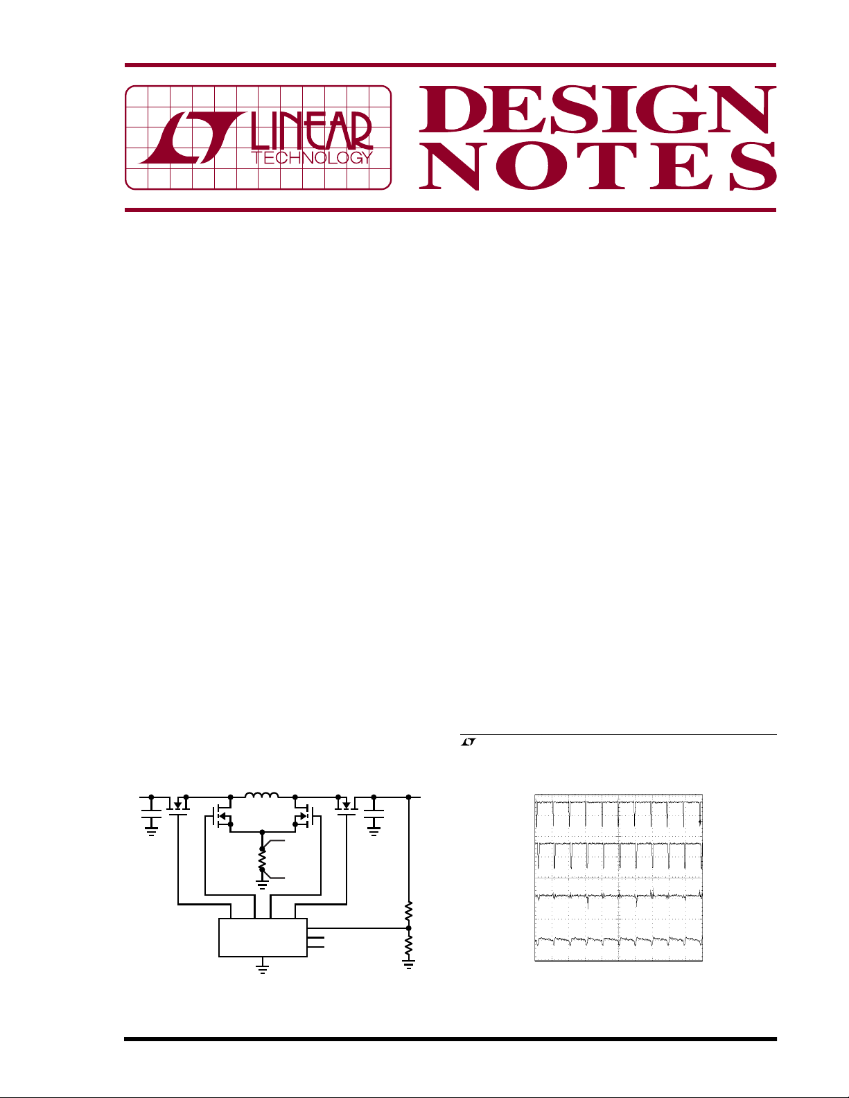
High Efficiency 4-Switch Buck-Boost Converter
Figure 1 shows a simplified LTC3780 4-switch buckboost converter. When V
operates in buck mode. With switch D on and switch C off,
switches A and B turn on and turn off alternately, as they
would in a typical synchronous buck regulator. Conversely, when V
ates in boost mode. With switch A on and synchronous
switch B off, switch C and synchronous switch D turn on
and turn off alternately, behaving as a typical synchronous boost regulator.
When V
mode. Switches A and D are on for most of each period.
®
Brief connections between VIN and ground, and V
ground, are made through the inductor and switches B-D
and A-C to regulate the output voltage. In buck-boost
mode, inductor peak-to-peak current is much lower than
that of SEPIC converters and traditional buck/boost converters. Figure 2 shows the inductor current and switch
node waveforms.
Low inductor ripple current and the use of synchronous
rectifiers allow the LTC3780 to achieve very high
, LTC, LT and Burst Mode are registered trademarks of Linear Technology
Corporation. Easy Drive is a trademark of Linear Technology Corporation.
All other trademarks are the property of their respective owners.
V
OUT
AC COUPLED
is close to V
IN
SW2
10V/DIV
SW1
10V/DIV
V
OUT
100mV/DIV
I
L
2A/DIV
exceeds V
IN
is lower than V
IN
, the controller is in buck-boost
OUT
5µs/DIV
, the LTC3780
OUT
, the LTC3780 oper-
OUT
DN369 F02
OUT
and
08/05/369
Figure 1. 4-Switch Buck-Boost Converter
Figure 2. Switch Nodes and Inductor Current Waveforms
(VIN = V
OUT
= 12V)
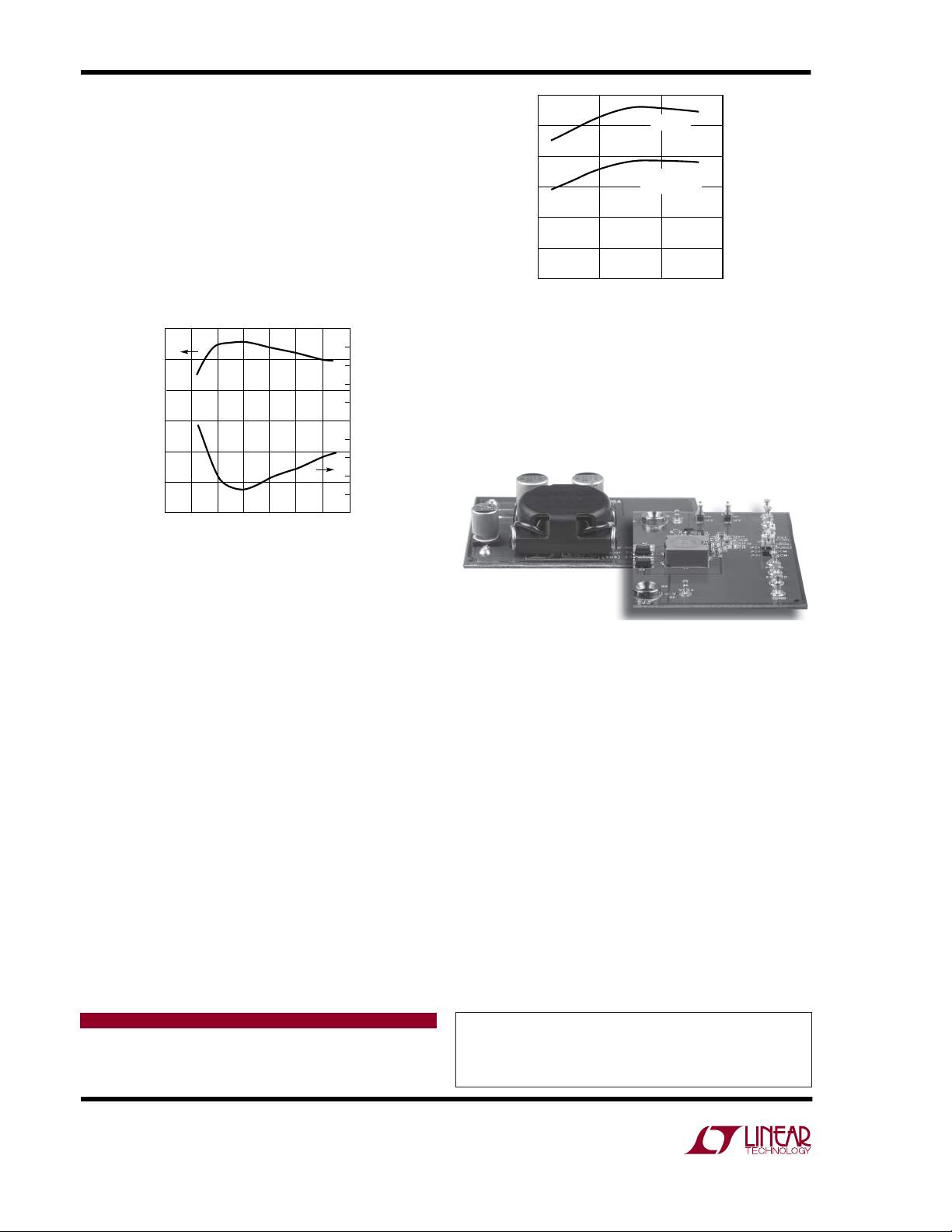
efficiency over a wide VIN range. When the input and
output voltages are both 12V, the 4-switch buck-boost
has 99% efficiency at 2A load and 98% at its maximum 5A
load (Figure 3). With its current mode control architecture, the converter has excellent load and line transition
response, minimizing the required filter capacitance and
simplifying loop compensation. As a result, very little filter
capacitance is required. The single sense resistor structure dissipates little power (compared with multiple resistor sensing schemes) and provides consistent current
information for short circuit and overcurrent protection.
100
95
90
85
EFFICIENCY (%)
80
75
70
0
510
20 30 35
15 25
VIN (V)
DN369 F03
10
9
8
POWER LOSS (W)
7
6
5
4
3
2
1
0
100
VIN (V)
LTC3780
SEPIC
CONVERTER
DN369 F04
95
90
85
EFFICIENCY (%)
80
75
70
5101520
Figure 4. Efficiency Comparison Between the LTC3780
and a SEPIC Converter (V
OUT
= 12V, I
LOAD
= 5A)
shutting down the whole circuit, the LTC3780 circumvents
this problem by forcing the converter into buck mode and
using current foldback to limit the inductor current.
Figure 3. Efficiency and Power Loss
(V
OUT
= 12V, I
LOAD
= 5A)
Replacing a SEPIC Converter
This single inductor buck-boost approach has high power
density and high efficiency. Compared with a coupled
inductor SEPIC converter, its efficiency can be 8% higher.
Figure 4 shows the efficiency comparison between the
LTC3780 4-switch buck-boost and a typical SEPIC converter. Note that a SEPIC converter has a maximum switch
voltage equal to the input voltage plus the output voltage.
So for a given maximum input voltage, a SEPIC would
dictate the use of a higher voltage external switch than is
required with the LTC3780. Moreover, the typical inductor
occupies about 1/5th of a SEPIC transformer’s footprint,
less than 1/15th the volume and less than one-half the
profile, as shown in Figure 5.
Protection for Boost Operation
The basic boost regulator topology provides no short circuit protection. When the output is pulled low, a large
current can flow from the input to the output. Without
Data Sheet Download
http://www.linear.com
SEPIC
LTC3780 Buck Boost
Figure 5. Inductor Size Comparison Between the LTC3780
5A/12V Converter (Right, 12.7mm × 12.7mm × 4mm) and
a Typical SEPIC (Left, 21mm × 21mm × 10.8mm)
Simplify
For certain applications such as those requiring low
current or not requiring current sinking, Switch D can be
replaced with a Schottky diode. This simplified topology
has approximately 2% lower efficiency.
Conclusion
The LTC3780 is a constant frequency current mode buckboost switching regulator controller that allows the input
voltage to be above, below or equal to the output voltage.
Its high efficiency, high power density and single inductor
topology make this product ideal for automotive, telecom,
medical and battery-powered systems.
For applications help,
call (408) 432-1900, Ext. 2593
Linear Technology Corporation
1630 McCarthy Blvd., Milpitas, CA 95035-7417
(408) 432-1900 ● FAX: (408) 434-0507 ● www.linear.com
dn369f LT/TP 0805 305K • PRINTED IN THE USA
© LINEAR TECHNOLOGY CORPORATION 2005
 Loading...