

advertisement
High Accuracy Synchronous Step-Down Controller Provides
Output Tracking and Programmable Margining –
Design Note 364
Charlie Zhao
Introduction
Output voltage tracking and margining are two increasingly popular features in power supply designs for high
performance server, ASIC and memory systems. These
two functions are among the advanced features provided
in the LTC
®
3770, a wide operating range, high accuracy,
synchronous step-down DC/DC controller. The LTC3770
operates with input voltages from 4V to 32V, generating
output voltages down to 0.6V with its highly accurate
±0.67% 0.6V reference voltage. It has a constant on-time,
valley current mode control architecture, which allows the
LTC3770 to operate at very low duty cycles with fast
transient response. The current sensing resistor is optional: leave it out for high efficiency, or in for most
accurate current limit.
MARGIN1
MARGIN0
TRACK
INTV
CC
R1
39k
R2
11k
C
1000pF
PGOOD
INTV
R
PG
V
OUT
C5
220pF
R3
95.3k
1%
R4
30.1k
1%
R
C
10k
1%
C1
CMPZ4683
C5
100pF
R
133k
1%
D2
3V
ON
100k
PGOOD
1
V
RNG
2
V
FB
3
I
TH
4
SGND
5
MARGIN1
6
MARGIN0
7
I
ON
8
V
REFIN
R5
V
REFOUT
10k
91011 1213141516
R6 82k
RUN INTV
V
IN
CC
R
RUN
100k
V
OUT
32 31 30 29 28 27 26 25
RUN
FCB
V
ON
MPGM TRACK/SS
C
0.01µF
Z0 BOOST TG SW
LTC3770EUH
PLLFLTR PLLIN VINV
R
PL
10k
C
PL
1000pF
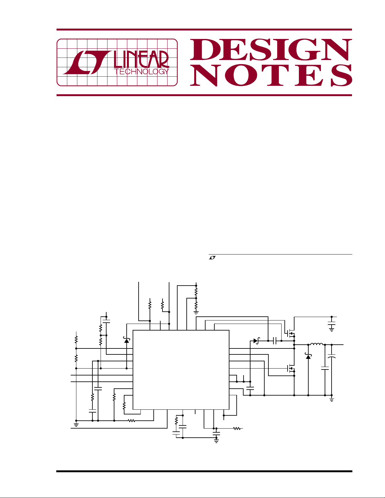
Figure 1 shows a 2.5V, 10A power supply with a 5V to 28V
input range. The switching frequency of the converter can
be selected by an external resistor, R
sated for variations in input supply voltage, or the controller can be synchronized to an external clock via an internal
phase-lock loop. Figure 2 shows the efficiency of the
circuit versus load current.
Start-Up and Shut Down Output Tracking
The LTC3770 output voltage can track another supply via
the TRACK/SS pin. Tracking and sequencing functions
allow the user to easily optimize the start-up and shut
down of multiple supplies, such as system core and I/O
, LTC and LT are registered trademarks of Linear Technology Corporation.
All other trademarks are the property of their respective owners.
CC
R7
23.2k
1%
R8
26.7k
1%
C1
D
B
C
10µF
6.3V
0.22µF
VCC
CMDSH-3-LTC
24
SENSE+
23
SENSE–
22
PGND
21
BG
INTV
20
DRV
CC
INTV
CC
Z2
Z1
INSNSZVIN
INTV
P
C
VIN
0.1µF
CC
CC
19
18
17
RV
IN
10Ω
V
IN
, and is compen-
ON
C
10µF
50V
L1
1.8µH
BI TECH
HM65-H1R8-TB
D1
B340LA
C2
22µF
6.3V
×3
M1
PH3230
M2
PH3230
V
IN
5V TO 28V
IN
V
OUT
2.5V
10A
+
C4
180µF
4V
DN364 F01
05/05/364
Figure 1. High Efficiency 5V-28VIN to 2.5V/10A Synchronous Buck Converter with Tracking and Margining
100
98
96
94
92
90
88
EFFICIENCY (%)
86
84
82
80
0
2
VIN = 5V
VIN = 12V
6
4
LOAD CURRENT (A)
8
10
DN364 F02
Figure 2. Efficiency Curves of the
LTC3770 Converter in Figure 1
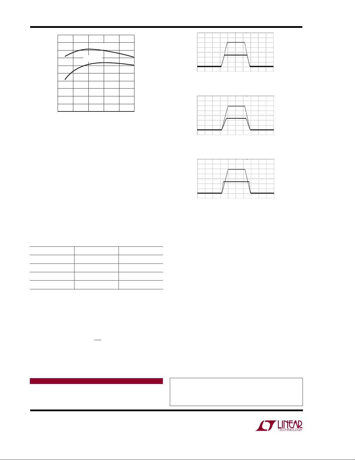
supplies. The tracking can be coincident or ratiometric, as
shown in Figure 3.
Programmable Voltage Margining
Voltage margining is the dynamic adjustment of the
output voltage to its worst-case operating value during
production test in order to stress the load circuitry, verify
control/protection functionality of the board and confirm
system reliability. The LTC3770 has two logic control
pins, MARGIN1 and MARGIN0, to enable margin up for
higher output voltage or margin down for lower output
voltage. Table 1 shows a summary of the configurations.
Table 1. Margining Function
MARGIN1 MARGIN0 MODE
Low Low No Margining
Low High Margin Up
High Low Margin Down
High High No Margining
The magnitude of the margin voltage shift is programmed
by selecting the ratio of two resistors, R5 and R6 in
Figure 1. When the margining function is enabled, the
error amplifier reference voltage is adjusted to:
R
VVV
=±
REFIN
⎛
06 118
..•
⎜
⎝
5
⎞
⎟
⎠
R
6
For example, ±5% margining can be achieved by selecting R5 = 13k and R6 = 510k.
EXTERNAL
VOLTAGE
1V/DIV
V
OUT
1V/DIV
20ms/DIV
DN364 F03a
(3a) Coincident Tracking
EXTERNAL
VOLTAGE
1V/DIV
V
OUT
1V/DIV
20ms/DIV
DN364 F03b
(3b) Ratiometric Tracking
EXTERNAL
VOLTAGE
1V/DIV
V
OUT
1V/DIV
20ms/DIV
DN364 F03c
(3c) Special Ratiometric Tracking
Figure 3. Up/Down Output Tracking. Upper Waveform:
External Voltage; Lower Waveform: Output Voltage of the
LTC3770 Converter
Additional Features
The LTC3770 provides very strong gate drivers allowing
up to 25A output currents, programmable current limit,
output overvoltage protection and input undervoltage
lockout. Other features include power good monitor,
programmable soft-start, selectable discontinuous operation mode or forced continuous mode at light load and
adjustable dead time between the top gate and bottom
gate signals to optimize efficiency.
Conclusion
The LTC3770 has an accurate 0.6V reference voltage and
a wide operating range. It includes advanced functions
usually implemented by additional ICs—such as output
tracking and programmable voltage margining. Available
package options are a thermally enhanced 5mm × 5mm
QFN package and a leaded 28-pin SSOP.
Data Sheet Download
http://www.linear.com
Linear Technology Corporation
1630 McCarthy Blvd., Milpitas, CA 95035-7417
(408) 432-1900 ● FAX: (408) 434-0507 ● www.linear.com
For applications help,
call (408) 432-1900, Ext. 2593
dn364f LT/TP 0505 409K • PRINTED IN THE USA
© LINEAR TECHNOLOGY CORPORATION 2005
 Loading...