

DESIGN IDEAS L
V
IN
LT3756
L1A, B
22µH 2×
OVP = 95V
GNDV
C
INTV
CC
INTV
CC
SHDN/UVLO FB
V
REF
ISP
1M
499k
2.2µF
100V
×2
2.2µF
100V
×5
4700pF
0.1µF
10k
23.2k
10k
42.2k
250kHz
1%
4.7µF
30.9k
100k
CTRL
0.018Ω
Si7322DN
0.068Ω
1.8M
24.3k
I
LED
1.5A
83V
LED
STRING
OPENLED
PWM
SS
R
T
ISN
GATE
SENSE
PWMOUT
PDS5100
Q1A, B
L1 = 2× SERIES SLF12575T-220M4R0
Q1 = 2× PARALLEL Si7322DN
VIN= PV
IN
40V TO 60V
(LED CURRENT
REDUCED WHEN
VIN< 40V)
100V Controller in 3mm × 3mm QFN
or MSE Drives High Power LED Strings
from Just About Any Input
Introduction
Strings of high power solid-state
LEDs are replacing traditional lighting
technologies in large area and high
lumens light sources because of their
high quality light output, unmatched
durability, relatively low lifetime cost,
constant-color dimming and energy efficiency. The list of applications grows
daily, including LCD television backlights and projection system bulbs,
industrial and architectural lighting
systems, automotive headlamps, taillights and indicator lights, computer
monitors, street lights, billboards and
even stadium lights.
As the number of applications expands, so does the complexity of input
requirements for the LED drivers.
LED drivers must be able to handle
wide ranging inputs, including the
harsh transient voltage environment
presented by automotive batteries,
the wide voltage range of the Li-ion
cells and wallwart voltages. For LED
lighting manufacturers and designers, applying a different LED driver
for each application means stocking,
testing and designing with a wide
variety of LED controllers. This can
be an expensive and time-consuming
proposition. It would be far better to
use a controller that can be applied
to many solutions.
The LT3756 high voltage LED driver
features a unique topological versatility that allows it to be used in boost,
buck-boost mode, buck mode, SEPIC,
flyback and other topologies. Its high
power capability provides potentially
hundreds of watts of steady-state LED
power over a very wide input voltage
range. Its 100V floating LED current
sense inputs allow the LED string to
float above ground, as shown in the
buck mode and buck-boost mode topologies in this article. Excellent PWM
dimming architecture produces high
dimming ratios, up to 3000:1.
Linear Technology Magazine • January 2009
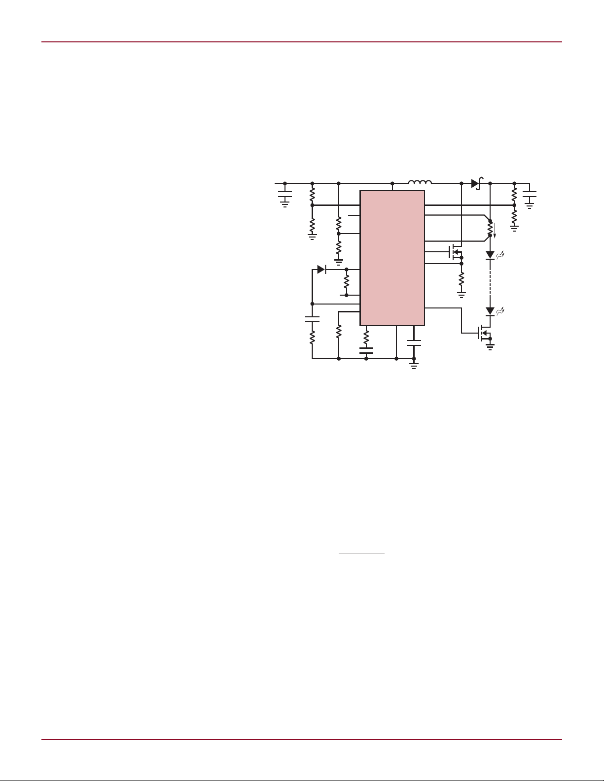
Figure 1. A 125W, 83V at 1.5A, 97% efficient boost LED driver for stadium lighting
A number of features protect the
LEDs and surrounding components.
Shutdown and undervoltage lockout,
when combined with analog dimming
derived from the input, provide the
standard ON/OFF feature as well as
a reduced LED current should the
battery voltage drop to unacceptably
low levels. Analog dimming is accurate and can be combined with PWM
dimming for an extremely wide range
of brightness control. The soft-start
feature prevents spiking inrush currents during start-up. The OPENLED
pin informs of open or missing LEDs
and the SYNC (LT3756-1) pin can be
used to sync switching to an external
clock.
The 16-pin IC is available in a
tiny QFN (3mm × 3mm) and an MSE
package, both thermally enhanced.
For applications with lower input voltage requirements, the 40VIN, 75V
LT3755 LED controller is a similar
option to the LT3756.
Although it is typically used as an
OUT
LED driver, the LT3756’s voltage FB
pin provides a well-regulated output
by Keith Szolusha
voltage if the constant current sense
voltage is not used. This is a side benefit
of the LT3756’s overvoltage protection
feature, in which the current control
loop is superceded by the FB voltage
loop in the case of an open LED string,
thus preventing the controller from a
running up the voltage in an effort to
maintain current.
125W Boost LED Driver for
Stadium Lights or Billboards
Lighting systems for stadiums, spotlights and billboards require huge
strings of LEDs running at high power.
The LT3756 controller can drive up
to 100V LED strings with its floating
sense resistor inputs ISP and ISN.
The 125W LED driver in Figure 1
accepts a wide-range 40V–60V input
taken from the output of a high power
transformer.
The LT3756’s high power GATE
driver switches two 100V MOSFETs
at 250kHz. This switching frequency
minimizes the size of the discrete components while maintaining high 97%
efficiency, thus producing a less-than-
3737
V
IN
LT3756
GNDV
C
INTV
CC
SHDN/UVLO
FB
V
REF
ISP
0.01µF
0.1µF
V
IN
10V TO
80V
PWM
69.8k
150kHz
100k
4.7µF
CTRL
0.05Ω
0.1Ω
M1
10µF
16V
6.2V
L1
33µH
D1
I
LED
1A
OPENLED
PWM
SS
R
T
ISN
GATE
PWMOUT
SENSE
196k
30.9k
D1: DIODES INC B2100
L1: SUMIDA CDRH8D38-330
M1: VISHAY SILICONIX Si4484EY
M2: VISHAY SILICONIX Si2307BDS
M3: VISHAY SILICONIX Si2328DS
Q1: MMBT5401
4.7k
12.4k
1 OR 2 LEDs
3.5V–7V
0A–1A
147k
1k
OPTIONAL
0V–12V FOR
0A–1A I
LED
Q1
51k
120k
M3
1N4448HWT
M2
10k
2.2µF
100V
×2
9.1k
EFFICIENCY (%)
VIN (V)
V
LED
= 7V
V
LED
= 3.5V
800
100
0
10 20 30 40 50 60 70
10
20
30
40
50
60
70
80
90
L DESIGN IDEAS
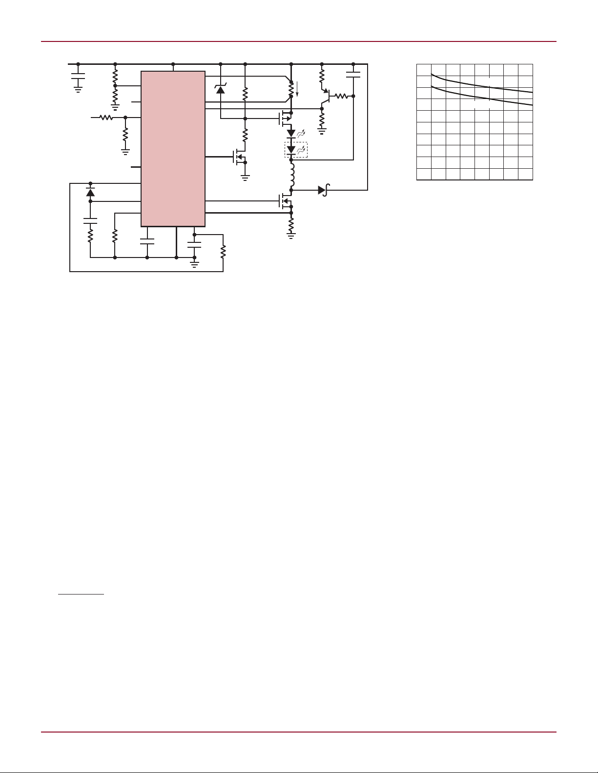
Figure 2. An 80VIN buck mode LED driver with PWM dimming for single or double LEDs
50°C discrete component temperature
rise—far more manageable than the
potential heat produced by the 83V
string of 1.5A LEDs.
Even if PWM dimming is not
required, the PWMOUT dimming
MOSFET is useful for LED disconnect
during shutdown. This prevents current from running through the string
of ground-connected LEDs—possible
under certain input conditions.
If an LED fails open or if the LED
string is removed from the high power
driver, the FB constant voltage loop
takes over and regulates the output at
95V until a proper string is attached
between LED+ and LED–. Without
overvoltage protection, the LED sense
resistor would see zero LED current
and the control loop would work hard
to increase its output. Eventually, the
output capacitor voltage would go over
100V, exceeding the maximum rating
of several components. While in OVP
the OPENLED status flag goes low.
High Voltage Buck Mode
LED Driver with High
PWM Dimming Ratio
When the input voltage is higher than
the LED string voltage, the LT3756
can serve equally well as a constant
current buck mode converter. For example, an automotive battery’s voltage
can present a wildly moving target,
38
38
from drooping voltages to dizzyingly
high voltage spikes, The buck mode
LED driver in Figure 2 is perfect for
such harsh environments. It operates
with a wide 10V-to-80V input range
to drive one or two 3.5V LEDs (7V) at
1A. In this case, both the V
IN
ISP and ISN current sense inputs can
go as high as 80V.
PWM dimming requires a level-shift
from the PWMOUT pin to the high
side LED string as shown in Figure 2. The maximum PWM dimming
ratio increases with higher switching frequency, lower PWM dimming
frequency, higher input voltage and
lower LED power. In this case, a 100:1
dimming ratio is possible with a 100Hz
dimming frequency, a 48V input, a
3.5V or 7V LED at 1A, and a 150kHz
switching frequency. Although higher
switching frequency is possible with
the LT3756, the duty cycle eventually
has its limits. Generous minimum
on-time and minimum off-time restrictions require a frequency on the lower
end of its range (150kHz) to meet both
the harsh high-VIN-to-low-V
to one 3.5V LED) and low-VIN-dropout
requirements (10V
particular converter.
The overvoltage protection of the
to 7V
IN
LED
LED
buck mode LED driver has a level
shift as well. Q1, a pnp transistor,
helps regulate the maximum allowable
pin and
(80VIN
) of this
Figure 3. Efficiency for the
buck mode converter in Figure 2
output capacitor voltage to a level just
beyond that of the LED string. Without
the level-shifted OVP network tied to
FB, an open LED string would result
in the output capacitor charging up to
the input voltage. Although the buck
mode components will survive this
scenario, the LEDs may not survive
being plugged back into a potential
equal to the input voltage. That is,
a single 3.5V LED might not survive
being connected directly to 80V.
Single Inductor Buck-Boost
Mode LED Driver
One increasingly common LED driver
requirement is that the ranges of both
the LED string voltage and the input
voltage are wide and overlapping. In
fact, some designers prefer to use the
same LED driver circuit for several
different battery sources and several
different LED string types. Such a
versatile configuration trades some
efficiency, component cost, and board
space for design simplicity, but the
tradeoffs are usually mitigated by the
significantly reduced time-to-market
by producing an essentially off-theshelf multipurpose LED driver.
The buck-boost mode topology
shown in Figure 4 uses a single
inductor and can both step-up and
step-down the input voltage to the LED
string voltage. It accepts inputs from
6V to 36V to drive 10V–50V LED strings
at up to 400mA. The PWM dimming
and OVP are level-shifted in a manner
similar to the buck mode for optimal
performance of these features.
The inductor current is the sum of
the input current and the LED string
Linear Technology Magazine • January 2009

V
IN
LT3756
GND
SHDN/UVLO
INTV
CC
499k
110k
2.49k
130k
1M
140k
0.25Ω
10V–50V
2.2µF
50V
s2
V
IN
9V TO 36V
(6V UVLO)
L1
22µH
M1: VISHAY SILICONIX Si7454DP
D1: DIODES INC. PDS3100
L1: SUMIDA CDRH127-220
4.7k
LED
–
LED
+
0.1µF
4.7µF
CTRL
V
C
5.1k
10k
100k
4700pF
OPENLED
SS
FB
ISN
ISP
PWMOUT
PWM
V
REF
SENSE
R
T
GATE
C
OUT
2.2µF
100V
s2
M1
D1
28.7k
400kHz
0.025Ω
V
IN
3906
I
LED
400mA
EFFICIENCY (%)
VIN (V)
V
LED
= 10V
V
LED
= 50V
3010
100
0
15 20 25
10
20
30
40
50
60
70
80
90
Figure 4. A buck-boost mode LED driver with wide-ranging V
current; the peak inductor current
is also equal to the peak switching
current—higher than either a buck
mode or boost topology LED driver
with similar specs due to the nature
of the hookup. The 4A peak switch
current and inductor rating reflects
the worst-case 9V input to 50V LED
string at 400mA.
Below 9V input, the CTRL analog
dimming input pin is used to scale back
LT3782A, continued from page 36
other out, thus reducing the total
output ripple by 50%, which in turn
reduces output capacitance requirements. The input current ripple is also
halved, which reduces the required
input capacitance and reduces EMI.
Finally, the power dissipated as heat is
spread out over two phases, reducing
the size of heat sinks or eliminating
them altogether.
24V at 8A from
a 10V–15V Input
Figure 1 shows a high power boost
application that efficiently produces a
24V/8A output from a 10V–15V input.
The LTC4440 high side driver is used
Linear Technology Magazine • January 2009
and V
IN
LED
the LED current to keep the inductor
current under control if the battery
voltage drops too low. The LEDs turn
off below 6V input due to undervoltage
lockout and will not turn back on until
the input rises above 7V, to prevent
flickering. In buck-boost mode, the
output voltage is the sum of the input
voltage and the LED string voltage. The
output capacitor, the catch diode, and
small) strings of high power LEDs.
It can be used in boost, buck-boost
mode, buck mode, SEPIC and flyback
topologies. Its high voltage rating, optimized LED driver architecture, high
performance PWM dimming, host of
protection features and accurate high
side current sensing make the LT3756
a single-IC choice for a variety of high
voltage input and high power lighting
systems.
to level shift the SGATE signals and
drive the synchronous MOSFETs. The
250kHz switching frequency optimizes
efficiency and component size/board
area. Figure 2 shows the layout. Proper
routing and filtering of the sense pins,
placement of the power components
and isolation using ground and supply planes ensure an almost jitter free
operation, even at 50% duty cycle.
Figure 3 shows the efficiency of the
circuit in Figure 1 with synchronous
MOSFETs (measured to 8A) and the
efficiency of an equivalent non-synchronous circuit using boost diodes
(measured to 6A). The 1% improvement
in peak efficiency may not seem significant, but take a look at the difference
in heat dissipation shown in Figure 4,
which shows thermal images of both
circuits under equivalent operating
conditions. The thermal advantages
of using synchronous switches are
clear.
Conclusion
The 2-phase synchronous boost
topology possible with the LT3782A
offers several advantages over a nonsynchronous or a single-phase boost
topology. Its combination of high efficiency, small footprint, heat sink-free
thermal characteristics and low input/output capacitance requirements
make it an easy fit in automotive and
industrial applications.
DESIGN IDEAS L
Figure 5. Efficiency for the buck-boost
mode converter in Figure 4
the power MOSFET can see voltages
as high as 90V for this design.
Conclusion
The 100V LT3756 controller is ostensibly a high power LED driver, but its
architecture is so versatile, it can be
used in any number of high voltage
input applications. Of course, it has
all the features required for large (and
L
L
3939
 Loading...