

advertisement
Buck or Boost: Rugged, Fast 60V Synchronous Controller
Does Both –
Design Note 370
Greg Dittmer
Introduction
Automotive, telecom and industrial systems are harsh,
unforgiving environments that demand robust electronic
systems. For example, an automotive battery system
may be a nominal 12V, 24V or 42V, but load dump
conditions can generate transients up to 60V. The
®
LTC
3703-5 is a synchronous switching regulator controller that can directly step down input voltages up to
60V and withstand transients up to 80V, making it ideal
for harsh environments. The ability to step down the high
input voltage directly allows a simple single inductor
topology, resulting in a compact high performance power
supply—in contrast to the low side drive topologies that
require bulky, expensive transformers.
Feature Rich Controller
The LTC3703-5 drives external logic-level N-channel
MOSFETs using a constant frequency, voltage mode
architecture. A high bandwidth error amplifier and patented line feed forward compensation provide very fast
line and load transient response. Strong 1Ω gate drivers
minimize switching losses—often the dominant loss component in high voltage supplies—even when multiple
MOSFETs are used for high current applications. Other
features include:
• Low minimum on-time (200ns) for low duty cycle
applications
• Precise 0.8V ±1% reference
• Programmable current limit utilizing the voltage drop
across the synchronous MOSFET to eliminate the need
for a current sense resistor
• Programmable operating frequency (100kHz to 600kHz)
• Low shutdown current (25µA), external clock synchro-
nization input and selectable pulse skip mode operation
• Packaged in a 16-pin narrow SSOP or a 28-pin SSOP
if high voltage pin spacing is desired.
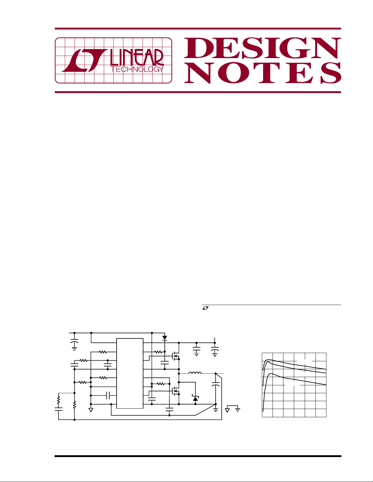
High Efficiency 48V to 3.3V/6A Power Supply
The circuit shown in Figure 1 provides direct step-down
conversion of a typical 48V telecom input rail to 3.3V at
6A. The circuit can handle input transients up to 60V
, LTC and LT are registered trademarks of Linear Technology Corporation.
All other trademarks are the property of their respective owners.
V
C
IN2
1µF
100V
X7R ×2
C
180µF
D1
B1100
4V TO 60V
+
OUT
+
6.3V
×2
IN
DN370 F01
C
IN1
220µF
63V
V
OUT
3.3V
6A
SGND PGND
100
90
80
EFFICIENCY (%)
70
60
0
VIN = 12V
VIN = 24V
VIN = 48V
12 4
I
LOAD
3
(A)
5
5V
C
+
33µF
10V
R
10k
C
C2
1000pF
R2
36.5k
1%
C2
R1
113k
C
C3
1%
2200pF
: SANYO 63MV220AX
: TDK C4532X7R2A105M
C
R
100Ω
IN1
IN2
VCC
D
10Ω
X7R
R
L1: PULSE ENG PA1119C
C
F
1µF
X7R
B
10Ω
B
BAS19
1µF
X7R
M1
Si7850DP
M2
Si7850DP
×2
L1
6.9µH
1
MODE/SYNC
30.1k
R
SET
2
C1
C
470pF
R
MAX
0.1µF
FSET
3
COMP
C1
4
FB
12.1k
5
I
MAX
6
INV
C
SS
7
RUN/SS
8
GND
: PANASONIC EEFUEOJ181
C
OUT
: AVX THJC336M010RJN
C
VCC
LTC3703-5
BOOST
V
DRV
BGRTN
V
IN
15
14
TG
0.1µF
13
SW
12
CC
11
CC
10
BG
9
Figure 1. Buck: 48V to 3.3V/6A Synchronous Step-Down Converter Figure 2. Efficiency of Figure 1’s Circuit
07/05/370
6
DN370 F02
without requiring protection devices or 80V if appropriate
MOSFETs are used. The frequency is set to 250kHz to
optimize efficiency and output ripple. Figure 2 shows a
= 24V
V
IN
V
OUT
50mV/DIV
INDUCTOR CURRENT
INDUCTOR CURRENT
5A/DIV
I
OUT
5A/DIV
50µs/DIV
DN370 F03
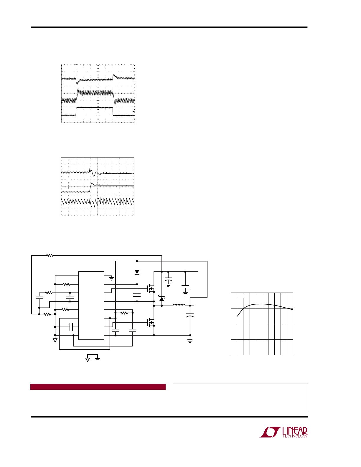
Figure 3. Load Transient Performance of Figure 1 Circuit
Shows 20µs Response Time to 5A Load Step
I
= 5A
OUT
V
OUT
50mV/DIV
VIN STEP
FROM
12V TO 50V
2A/DIV
AC COUPLED
10µs/DIV
DN370 F04
Figure 4. Line Transient Performance of Figure 1 Circuit
Shows Almost Complete Rejection of 12V to 50V Supply
Transient
mid-range efficiency of over 90% at 24V input and 83.5%
at 48V input. The loop is compensated for a 50kHz
crossover frequency which provides 20µs response time
to load transients (see Figure 3). The outstanding line
transient performance is shown in Figure 4. The 12.1k
R
resistor value is chosen to limit the inductor current
MAX
to about 12A during a short-circuit condition.
High Efficiency 12V to 24V/5A Synchronous StepUp Fan Power Supply
Synchronous boost converters have a significant advantage over non-synchronous boost converters in higher
current applications due to the low power dissipation of
the synchronous MOSFET compared to that of the diode
in a non-synchronous converter. The high power dissipation in the diode requires a much larger package (e.g.
2
D
PAK) than the small S8-size package required for the
synchronous MOSFET for the same output current.
Figure 5 shows the LTC3703-5 implemented as a synchronous step-up converter for generating 24V/5A from
12V—a common voltage for driving fans. This supply
achieves a peak efficiency over 96% (see Figure 6). The
LTC3703-5 is set to operate as a synchronous boost
converter by simply connecting the INV pin to greater than
2V. In boost mode, the BG pin becomes the main switch
and TG becomes the synchronous switch. Aside from this
phase inversion, boost mode operation is similar to buck
mode. In boost mode, the LTC3703-5 can produce output
voltages as high as 60V.
R1
C
C2
0.1µF
113k 1%
R
C1
10k
R2
3.92k
1%
R
C
100pF
R
MAX
SET
C1
C
0.1µF
30.1k
15k
SS
1
MODE/SYNC
2
FSET
3
COMP
4
FB
5
I
MAX
6
INV
7
RUN/SS
8
GND
BOOST
LTC3703-5
DRV
BGRTN
SGND PGND
16
V
IN
15
14
TG
13
SW
12
V
CC
11
CC
10
BG
9
D
B
CMDSH-3
C
B
0.1µF
X7R
R
F
10Ω
C
C
DRVCC
10µF
X7R
L1: VISHAY IHLP5050EZ
C
OUT1
C
OUT2
C
IN
M1, M2: Si7892DP
VCC
1µF
X7R
: SANYO 35MV220AX
: UNITED CHEMICON NTS60X5RIH106MT
: OSCON 20SP180M
C
OUT1
+
220µF
35V
×3
M1
B240A
L1
3.3µH
C
180µF
M2
20V
V
OUT
24V
5A
C
OUT2
10µF
50V
X5R
×2
V
IN
10V
TO 15V
+
IN
×2
DN370 F05
Figure 5. Boost: 12V to 24V/5A Synchronous Step-Up for Fan Power Supply
Data Sheet Download
http://www.linear.com
call (408) 432-1900, Ext. 2593
Linear Technology Corporation
1630 McCarthy Blvd., Milpitas, CA 95035-7417
(408) 432-1900 ● FAX: (408) 434-0507 ● www.linear.com
100
VIN = 12V
95
90
EFFICIENCY (%)
85
80
1234
LOAD CURRENT (A)
DN370 F06
50
Figure 6. Efficiency of Figure 5’s Circuit
For applications help,
dn370f LT/TP 0705 409K • PRINTED IN THE USA
© LINEAR TECHNOLOGY CORPORATION 2005
 Loading...