

Monolithic Synchronous Step-Down Regulator Delivers up to
12A from a Wide Input Voltage Range – Design Note 457
Charlie Zhao and Henry Zhang
Introduction
The LTC®3610 is a high power monolithic synchronous
step-down DC/DC regulator that can deliver up to 12A
of continuous output current from a 4V to 24V (28V
maximum) input supply. It is a member of a high current
monolithic regulator family (see Table 1) that features
integrated low R
N-channel top and bottom
DS(ON)
MOSFETs. This results in a high effi ciency and high
power density solution with few ex ternal components.
This regulator family uses a constant on-time valley
current mode architecture that is capable of operating
at very low duty cycles at high frequency and with very
fast transient response. All are available in low profi le
(0.9mm max) QFN packages.
Table 1. Comparison of LTC36XX Family Members
LTC3608 LTC3609 LTC3610 LTC3611
INPUT VOLTAGE
RANGE (V)
MAX LOAD
CURRENT (A)
QFN PACKAGE
SIZE (mm)
4 to 20 4.5 to 32 4 to 24 4.5 to 32
8 6 12 10
7 × 8 ×
4.5V TO 20V
GND
0.9
V
IN
7 × 8 ×
0.9
10μF
25V
INTV
10μF
25V
CC
0.1μF
9 × 9 ×
0.9
CMDHS-3
100pF
2200pF
f
10μF
25V
V
SW
12k
0.22μF
25V
OUT
= 650kHz
9 × 9 ×
0.9
PV
IN
SW
BOOST
RUN/SS
V
ON
PGOOD
V
RNG
I
TH
I
ON
SV
Typical Application Example
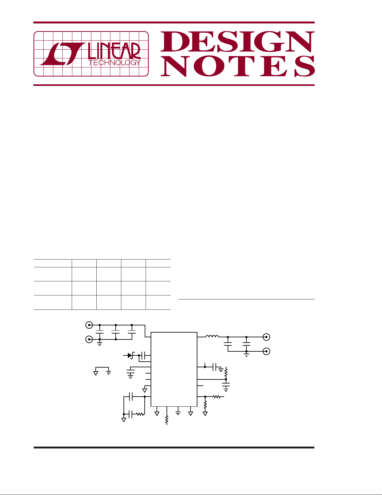
Figure 1 shows a typical application schematic of the
LTC 3608. This 7mm × 8mm regulator supplies 2.5V
at 8A maximum load current from a 4.5V to 20V input
source. This application switches at a nominal 650kHz,
which allows the use of low pro fi le inductor and capaci tors while maintaining high effi ciency. The switching
frequency can be easily adjusted by a resistor (R
Figure 1, connected to the I
pin). Figure 2 shows the
ON
operating effi ciency.
The FCB pin is connec ted to ground to force continuous
mode operation at ligh t load for both low noise and small
output ripple. The FCB pin can also be tied to INTV
to enable discontinuous mode for higher effi ciency at
light load. Soft-start is programmable with a capacitor
from the RUN/SS pin to ground. Forcing the RUN/SS
pin below 0.8V shuts down the device.
The LTC36XX family are valley current mode regulators so they inherently limit the cycle-by-cycle
L, LT, LTC and LTM are registered trademarks of Linear Technology Corporation.
All other trademarks are the property of their respective owners.
1μH
LTC3608
R
ON
162k
1%
IN
IHLP2525CZ-01
SW
4.7μF
10V
INTV
INTV
EXTV
PGND SGNDFCB
CC
CC
SV
IN
CC
V
FB
19.1k
1%
DN457 F01
60.4k
100μF
100μF
6.3V
6.3V
V
IN
1Ω
SV
IN
0.47μF
25V
1%
V
OUT
V
2.5V
8A
GND
OUT
ON
in
CC
01/09/457
Figure 1. 4.5V to 20V Input to 2.5V/8A High Density Step-Down Converter
100
95
90
85
80
75
70
EFFICIENCY (%)
65
60
55
50
0
VIN = 5V
VIN = 20V
13
4
2
LOAD CURRENT (A)
V
= 2.5V
OUT
FREQ = 650kHz
6
5
7
AN457 F02
8
Figure 2. Effi ciency vs Load Current of Figure 1
inductor cur
the R
rent. The induc tor current is sensed using
of the bottom MOSFET —no additional
DS(ON)
current sense resistor is required. The current limit
is also adjustable with the voltage at the V
When the V
pin is tied to ground, in the Figure 1
RNG
RNG
pin.
example, the current limit is set to about 16A.
25%, the maximum sense voltage is lowered to about
one sixth of its original value.
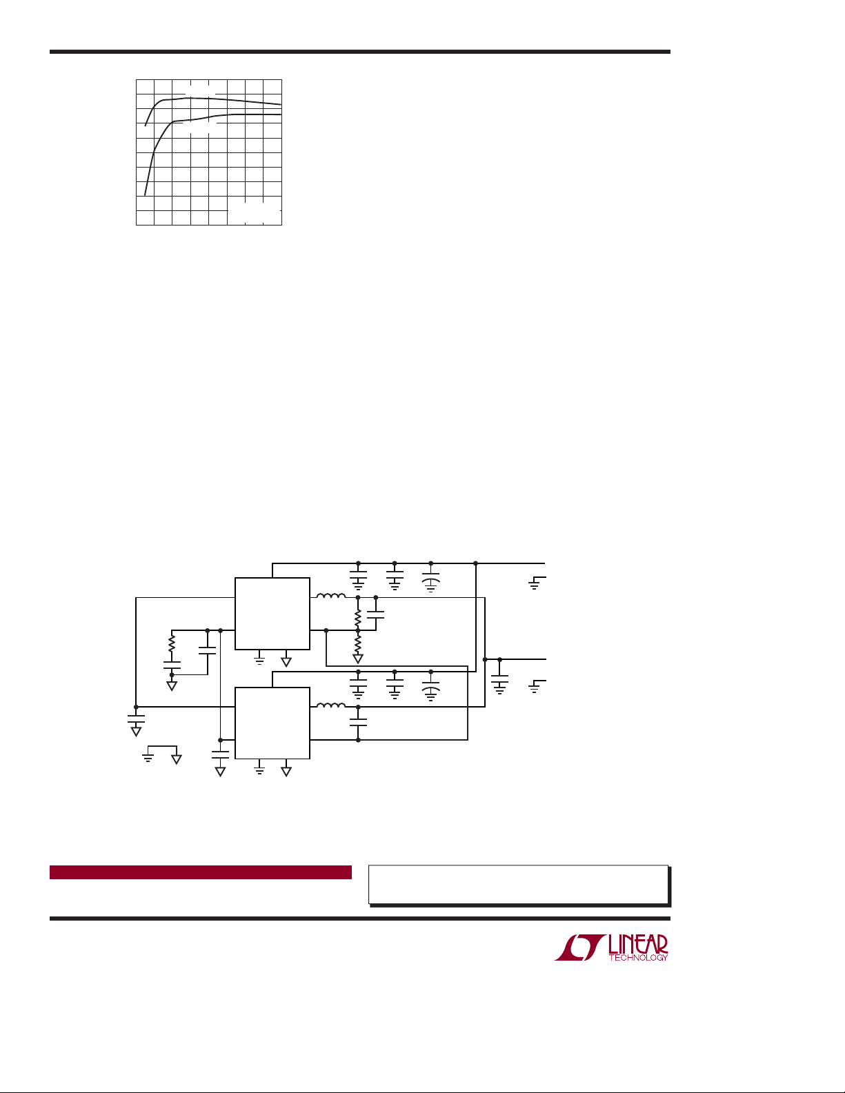
Paralleling Regulators for >12A
These parts can be easily paralleled for high output
current applications. Figure 3 shows a 1.2V/24A
application using t wo parallel LTC3610s. Because of the
valley current mode control architecture, the paralleled
regulators can operate at very low duty cycles with fast
transient response and excellent load balance.
The current sharing is simple. Connect the I
together, since the I
pin voltage determines the
TH
TH
pins
cycle-by-cycle valley inductor current. The feedback
pins of paralleled LTC3610s share a single voltage
divider. The RUN/SS pins are connected so that the
LTC3610s start up with same slew rate. The paralleled
LTC3610s have excellent thermal balance due to good
current sharing.
An open-drain logic power good output voltage monitor (PGOOD) is pulled low when the output voltage is
outside ±10% of the regulation point. In the case of
ov er vo lt ag e, th e in te rn al to p MO SF E T i s t ur ne d o ff an d
the bottom MOSFET is turned on until the overvoltage
condition clear s. The LTC36X X also includes a foldback
current limiting feature to further limit current in the
event of a short circuit. If the output drops more than
3.83k
1800pF
0.1μF
PV
IN
RUN/SS SW
LTC3610
I
TH
PGND SGND
RUN/SS SW
LTC3610
I
TH
I
TH
PGND SGND
PV
IN
100pF
I
TH
100pF
Figure 3. Two LTC3610s in Parallel Can Provide 24A Output Current
0.33μH
V
FB
V
FB
0.33μH
22pF
V
FB
V
FB
Conclusion
With broad input and output ranges, high current
capabilit y and high effi ciency, these monolithic regulators provide small size, low external component count
power solutions for many applications from communications infrastructure to industrial distributed
power systems.
V
IN
47μF
s8
11V TO 13V
GND
V
OUT
1.2V
24A
GND
10μF 10μF
22pF
60.4k
10μF
fSW = 750kHz
10μF
+
150μF
+
150μF
DN457 F03
Data Sheet Download
www.linear.com
Linear Technology Corporation
1630 McCarthy Blvd., Milpitas, CA 95035-7417
(408) 432-1900
●
FAX: (408) 434-0507 ● www.linear.com
For applications help,
call (408) 432-1900, Ext. 3258
dn457f LT/TP 0109 246K • PRINTED IN THE USA
© LINEAR TECHNOLOGY CORPORATION 2009
 Loading...