

Tiny Synchronous Step-Up Converter Starts Up at 700mV
Design Note 428
Dave Salerno
Introduction
Alkaline batteries are convenient because they’re easy to
fi nd and relatively inexpensive, making them the power
source of choice for portable instruments and devices
used for outdoor recreation. Their long shelf life also
makes them an excellen t choice for emergency equipment
that may see infrequent use but must be ready to go on a
moment’s notice. It is important that the DC/DC converters in portable devices operate over the widest possible
battery voltage range to ex tend batter y run time, and thus
save the user from frequent battery replacement.
Single-cell alkaline batteries, with a 1.6V to 0.9V range,
present a special challenge to DC/DC converters because
of their low voltage and the fact that their internal resistance increases as the battery discharges. Thus, a DC/DC
converter that can both start up and operate effi ciently at
low input voltages is ideally suited for single-cell alkaline
products.
®
The LTC
3526L is a 1MHz, 550mA synchronous step-
up (boost) converter with a wide input voltage range of
0.7 V to 5V and an output voltage range of 1.5V to 5.25V.
Housed in a 2mm × 2mm DFN package, the LTC3526L has
a typical startup voltage of just 700mV, with operation
down to 400mV once started. Despite the LTC3526L’s
tiny solution size, it includes many advanced features,
including output disconnect, short circuit protection, low
noise fi xed frequency operation, internal compensation,
®
soft-s tart, thermal shutdown and Burst Mode
o p e r a t i o n
for high effi ciency at light load. For low noise applica-
®
tions, the LTC
3526LB offers fi xed frequency operation
at all load currents. With an output voltage range that
extends down to 1.5V, the LTC3526L and LTC3526LB can
eve n be us ed in a pp lic at io ns pr ev io usl y r eq uir in g a b oo st
converter followed by a buck converter.
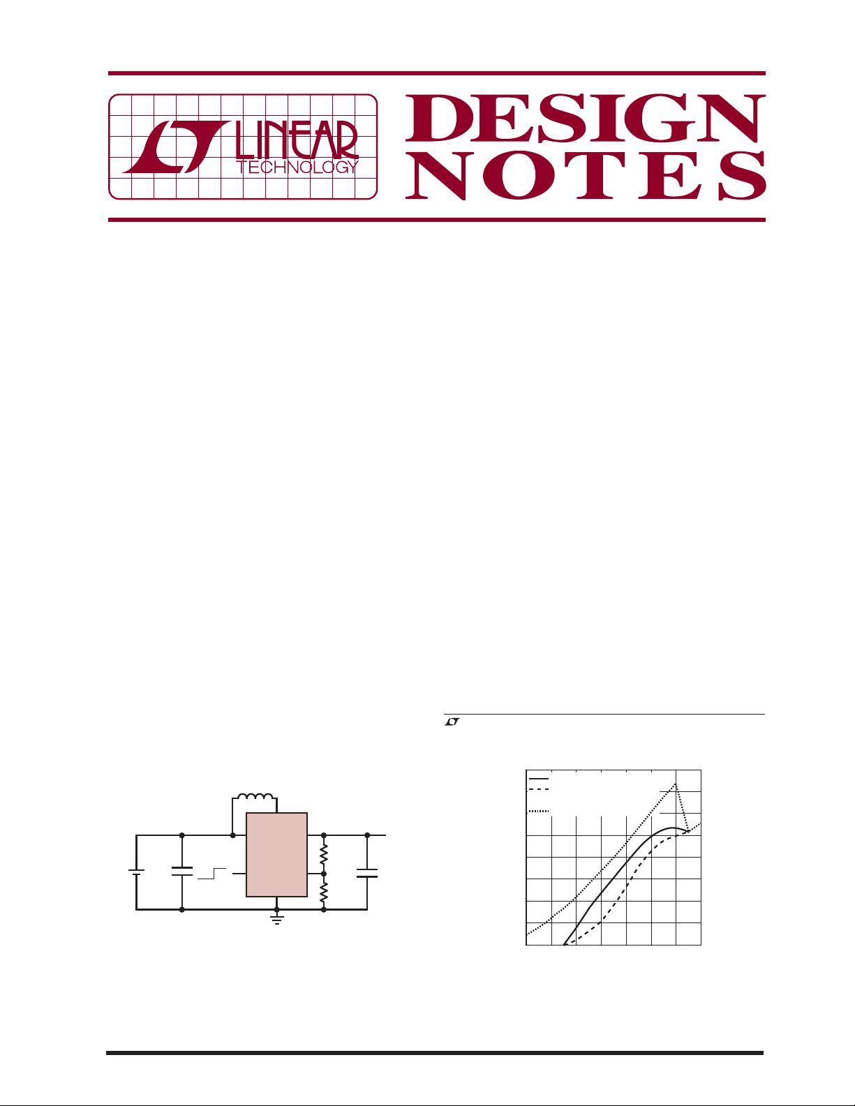
A typical single-cell boost application is shown in Figure
1. In this example the LTC3526LB is used to generate
1.8V for a Bluetooth radio application. The LTC3526LB
was selected for its small size, minimal external component count and low-noise, fi xed frequency operation
at all load currents. A graph of output current capability
versus input voltage is shown in Figure 2. Note that the
converter starts up at 700mV at no load and once run-
, LT, LTC, LTM and Burst Mode are registered trademarks of Linear Technology
Corporation. All other trademarks are the property of their respective owners.
L1
4.7μH
V
IN
0.7V TO 1.8V
+
C
IN
2.2μF
: MURATA GRM188R61A225K
C
IN
L1: FDK MIPF2520D4R7
: MURATA GRM188R60J475K
C
OUT
OFF ON
SW
V
IN
LTC3526LB
SHDN
GND
V
V
OUT
R2
825k
FB
R1
1.62MEG
DN428 F01
1.8V
C
OUT
4.7μF
OUT
Figure 1. Single-Cell 1.8V Boost Converter for a Bluetooth
Radio Application Features a Low Startup Voltage
and Uses a Monolithic Chip Inductor for a Maximum
Component Height of Just 1mm.
11/07/428
400
350
300
250
200
LOAD (mA)
150
100
STARTUP (RESISTIVE LOAD)
STARTUP (CONSTANT
CURRENT LOAD)
AFTER STARTUP
50
0
0.4
1.20.8 1.6
VIN (V)
Figure 2. Maximum Load
Capability During and After
Startup for the Circuit in Figure 1.
1.81.00.6 1.4
DN428 F02
ning, can deliver 25mA of output current with an input
voltage of only 400mV. The 1MHz switching frequency
allows the use of small, low profi le inductors, such as
the monolithic chip inductor shown in this application.
This provides a complete solution with a footprint that’s
2
just 36mm
with a 1mm profi le.
Many new battery types are available to the consumer,
some of which are aimed at high-tech, high power applications. One of these is the disposable lithium AA /A AA
battery, which offers a signifi cant improvement in runtime over traditional alkaline batteries. Furthermore, in
applications that see infrequent use, the long shelf life
of lithium batteries gives them a performance edge over
nickel-based rechargeable batteries, which have a high
self-discharge rate.
L1
4.7μH
V
IN
1.4V TO 3.6V
+
C
IN
2.2μF
+
: MURATA GRM188R61A225K
C
IN
L1: TAIYO-YUDEN NP03SB4R7M
: MURATA GRM21BR61A106K
C
OUT
OFF ON
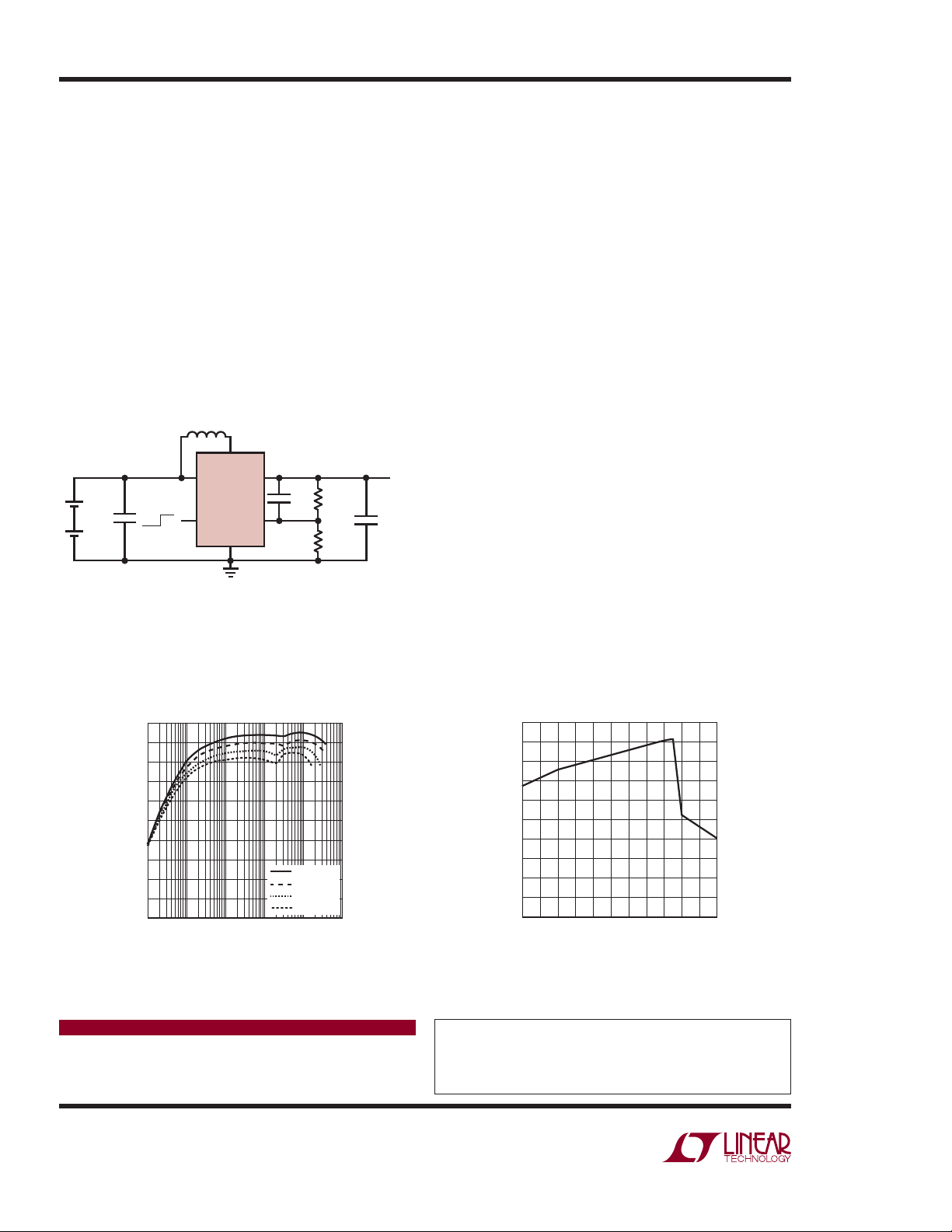
Figure 3. Two AA Lithium Cell to 3.3V Boost Converter with
250mA Load Capability Maintains High Effi ciency Over Three
Decades of Load Current and Operates with VIN ≥ V
V
IN
LTC3526L
SHDN
GND
SW
V
OUT
C
OUT
10μF
DN428 F03
.
OUT
3.3V
V
OUT
C
R2
FF
22pF
FB
2MEG
R1
1.13MEG
One characteristic of the lithium battery is that its voltage
c a n b e a s h i g h a s 1 . 8 V w h e n t h e b a t t e r y i s f r e s h , c o m p a r e d
to 1.6V for a typical alkaline battery. This is a problem
for 2-cell alkaline applications that use a traditional boost
converter to produce a 3.3V output from an alkaline
3.2V max input. Most boost converters cannot maintain
regulation when the input is higher than the output, as it
is with two fresh lithium batteries (3.6V).
The LTC3526L solves this problem by maintaining regulation even when the input voltage exceeds the output
voltage. An example of a 2-cell to 3.3V boost converter
using the LTC3526L is shown in Figure 3. A small feedforward c apacitor has been added across the upp er divider
resistor to reduce output ripple in Burst Mode
operation.
Effi ciency vs load curves are shown in Figure 4. These
curves demonstrate the high effi ciency at light load made
possible by the low 9μA quiescent current of Burst Mode
operation. The curve in Figure 5 illustrates the effi ciency
at input voltages above and below the output voltage.
Conclusion
The LTC3526L is a highly integrated step-up DC/DC
converter in a 2mm × 2mm package designed to easily fi t a wide variety of battery-powered applications.
Low startup and operating voltages extend runtime in
single-cell applications. It even regulates in step-down
situations where the fresh battery voltage (V
exceed V
. For high effi ciency at light loads, or low
OUT
) may
IN
noise operation, it offers a choice of Burst Mode or fi xed
frequency operation.
100
90
80
70
60
50
40
EFFICIENCY (%)
30
20
10
0
0.01 0.1 100 1000101
LOAD (mA)
VIN = 3V
= 2.4V
V
IN
= 1.8V
V
IN
= 1.4V
V
IN
DN428 F04
Figure 4. Effi ciency vs Load for
the Circuit in Figure 3.
Data Sheet Download
www.linear.com
Linear Technology Corporation
1630 McCarthy Blvd., Milpitas, CA 95035-7417
(408) 432-1900
●
FAX: (408) 434-0507 ● www.linear.com
100
95
90
85
80
75
70
EFFICIENCY (%)
65
60
55
50
1.4
2.21.8 2.6 2.8 3.0 3.2 3.4
VIN (V)
3.62.01.6 2.4
DN428 F05
Figure 5. Effi ciency vs VIN for the Circuit
in Figure 3 (at 100mA Load Current).
For applications help,
call (408) 432-1900, Ext. 3725
dn428f LT/TP 1107 305K • PRINTED IN THE USA
© LINEAR TECHNOLOGY CORPORATION 2007
 Loading...