


Supercapacitor-Based Power Backup System Protects Volatile
Data in Handhelds when Power Is Lost
Design Note 498
Jim Drew
Introduction
Handheld electroni c devices play a key role in our everyday
lives. Because dependabilit y is paramount, handhelds are
carefully engineered with lightweight power sources for
reliable use under normal conditions. But no amount of
careful engineering can prevent the mistreatment they
will undergo at the hands of humans. For example, what
happens when a factory worker drops a bar code scanner, causing the battery to pop out? Such events are
electronically unpredictable, and important data stored
in volatile memory would be lost without some form of
safety net—namely a short-term power holdup system
that stores su ffi cient energ y to supply standby power until
the battery can be replaced or the data can be stored in
permanent memory.
Supercapacitors are compact, robust, reliable and can
support the power requirements of a backup system for
short-term power-loss events. Like batteries, they require
careful charging and power regulation at the output. The
Q1
FDC604P
V
4.7μF
6.3V
X5R
0603
2.2μF
10V
X5R
0603
C2
100k
13
3
15
12
8
9
R3
R8
348k
IN
R1
191k
C1
R2
121k
V
IN
PFI
+
C
–
C
EN_CHG
PROG
LTC3226EUD
GND
17
GATE
V
OUT
CPO
V
MID
CPO_FB
LDO_FB
RST_FB
RST
PFO
CAPGOOD
D2
D1N4148
5
1
16
14
10
4
6
7
2
11
®
3226 is a 2-cell series supercapacitor charger with a
LTC
PowerPath™ controller that simplifi es the design of backup
systems. Specifi cally, it includes a charge pump supercapacitor charger with programmable output voltage and
automatic cell vol tage balancing, a low dropout re gulator and
a power-fail comparator for switching between normal and
backup modes. Low input noise, low quiescent current and
a compact footprint make the LTC3226 ideal for compact,
handheld, battery-powered applications. The device comes
in a 3mm × 3mm 16-lead QFN package.
Backup Power Application
Figure 1 shows a power holdup system that incorporates
a supercapacitor stack with the capacity to provide
standby power of 165mW for about 45 seconds in the
absence of battery power. An LDO converts the output
of the supercapacitor stack to a constant voltage supply
during backup mode.
L, LT, LTC, LTM, Linear Technology and the Linear logo are registered trademarks and
PowerPath is a trademark of Linear Technology Corporation. All other trademarks are
the property of their respective owners.
V
OUT
C3
+
0.1μF
16V
X7R
C4
0.1μF
16V
X7R
*C5
3F
2.7V
R4
R6
3.83M
R5
1.21M
255k
R9
475k
R7
80.6k
*NESS CAP ESHSR-0003C0-002R7
+
*C6
3F
2.7V
C7
47μF
6.3V
X5R
1206
20%
R10
1.07M
R11
154k
3
+
LT6703HV-3
R12
475k
4
1
2
dn498 F02
V
SB
01/12/498
Figure 1. A Typical Power Backup System Using Supercapacitors
Designing a power backup system is easy with the
LTC3226. For example, take a dev ice that has an operating
current of 150mA and a standby current (I
) of 50mA
SB
when powered from a single- cell Li-Ion batter y. To ensure
that a charged batter y is present, the power-fail comparator (PFI) high trigger point is set to 3.6V. The device enter s
standby mode when the battery voltage reaches 3.15V
and enters backup mode at 3.10V (V
holdup power for a time period (t
HU
BAT(MIN)
) of about 45 seconds.
), initializing
The standby mode tr igger level is controlled by an exter nal
comparator circuit while the backup mode trigger level
is controlled by the PFI comparator. While in backup
mode, the device must be inhibited from entering full
operational mode to prevent overly fast discharge of the
supercapacitors.
The design begins by setting the PFI trigger level. R2 is
set at 121k and R1 is calculated to set the PFI trigger level
at the PFI pin (V
V
BAT(MIN)–VPFI
R1=
PFI
V
PFI
) to 1.2V.
•R2= 191.6kΩ
Set R1 to 191k.
The hysteresis on the V
pin needs to be extended to
IN
meet the 3.6V trigger level. This can be accomplished by
adding a series combination of a resistor and diode from
the PFI pin to the PFO pin. V
V
IN(HYS)
is 0.4V.
f
V
+ V
PFI
–
PFI(HYS)
V
PFI(HYS)
R2
20mV and V
R8 =
is 0.5V, V
IN(HYS)
–V
f
•(R1+ R2)
PFI(HYS)
•R1= 349.3kΩ
is
Set R8 to 348k.
Set the LDO backup mode output voltage to 3.3V by
setting R7 to 80.6k and calculating R6. V
V
R6 =
OUT–VLDO(FB)
V
LDO(FB)
•R7= 251.9kΩ
LDO(FB)
is 0.8V.
Set R6 to 255k.
V
R4=
CPO–VCPO(FB)
V
CPO(FB)
•R5= 3.78MΩ
Let R4 equal 3.83M.
As the voltage on the supercapacitor stack starts to
approach V
in backup mode, the ESR of the two
OUT
supercapacitors and the output resistance of the LDO
must be accounted for in the calculation of the minimum
voltage on the supercapacitors at the end of t
. Assume
HU
that the ESR of each supercapacitor is 100mΩ and the
LDO output resistance is 200mΩ, which results in an
additional 20mV to V
current. V
voltage (ΔV
OUT(MIN)
is set to 3.1V, resulting in a discharge
) of 1.88V on the supercapacitor stack.
SCAP
OUT(MIN)
due to the 50mA standby
The size of each supercapacitor can now be determined.
C
SCAP
= 2•
SB
ΔV
= 2.39F
SCAP
•t
I
HU
Each supercapacitor is chosen to be a 3F/2.7V capacitor
from Nesscap (ESHSR-0003C0-002R7).
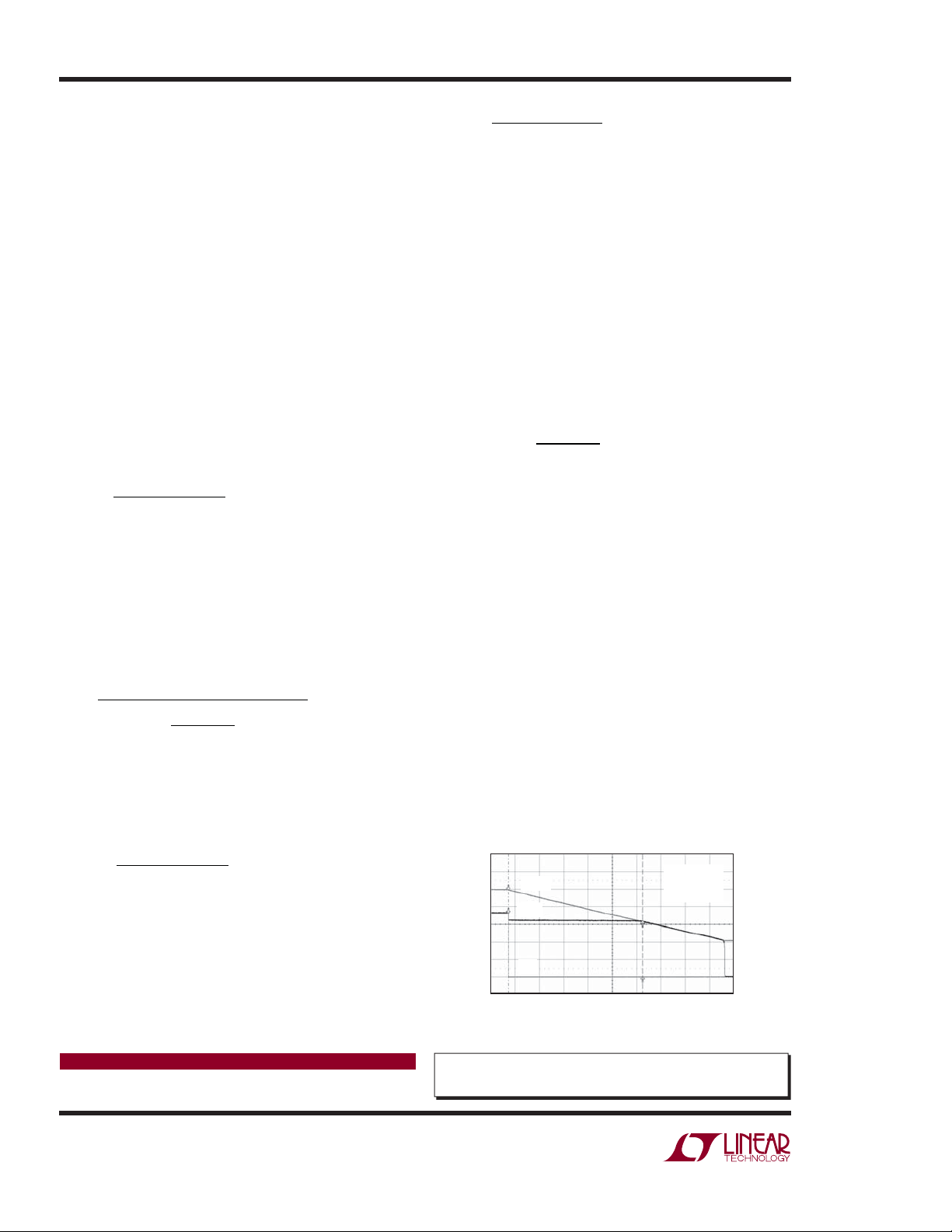
Figure 2 shows the actual backup time of the system with
a 50mA load. The backup time is 55.4 seconds due to the
larger 3F capacitors used in the actual circuit.
Conclusion
High performance handheld devices require power
backup systems that can power the device long enough
to safely store volatile data when the bat tery is suddenly
removed. Supercapacitors are compact and reliable
energy sources in these systems, but they require
specialized control systems for charging and output
voltage regulation. The LTC3226 makes it easy to build
a complete backup solution by integrating a 2-cell
supercapacitor charger, PowerPath controller, an LDO
regulator and a power-fail comparator, all in a 3mm ×
3mm 16-lead QFN package.
VIN = 3.6V
= 50mA
I
OUT
LDO = 3.3V
1V/DIV
V
SCAP
The fully charged voltage on the series-connected
supercapacitors is set to 5V. This is accomplished with
a voltage divider network between the CPO pin and the
CPO_FB pin. R5 is set to 1.21M and R4 is calculated.
CPO(FB)
is 1.21V.
V
Data Sheet Download
www.linear.com
Linear Technology Corporation
1630 McCarthy Blvd., Milpitas, CA 95035-7417
(408) 432-1900
●
FAX: (408) 434-0507 ● www.linear.com
V
IN
10s/DIV
Figure 2. Backup Time Supporting 50mA Load
For applications help,
call (978) 656-3768
dn498f LT/TP 0112 196K • PRINTED IN THE USA
© LINEAR TECHNOLOGY CORPORATION 2011
dn498 F02
 Loading...