

Supercapacitors Can Replace a Backup Battery for
Power Ride-Through Applications − Design Note 450
Jim Drew
Introduction
Supercapacitors (or ultracapacitors) are fi nding their way
in to an increa sing number of applications for short-term
energy storage and applications that require intermittent
high energy pulses. One such application is a power ridethrough circuit, in which a backup energy source cuts
in and powers the load if the main power supply fails
for a short time. This type of application has typically
been dominated by batteries, but electric double layer
capacitors (EDLCs) are fast making inroads as their
price-per-farad, size and effective series resistance per
capacitance (ESR/C) continue to decrease.
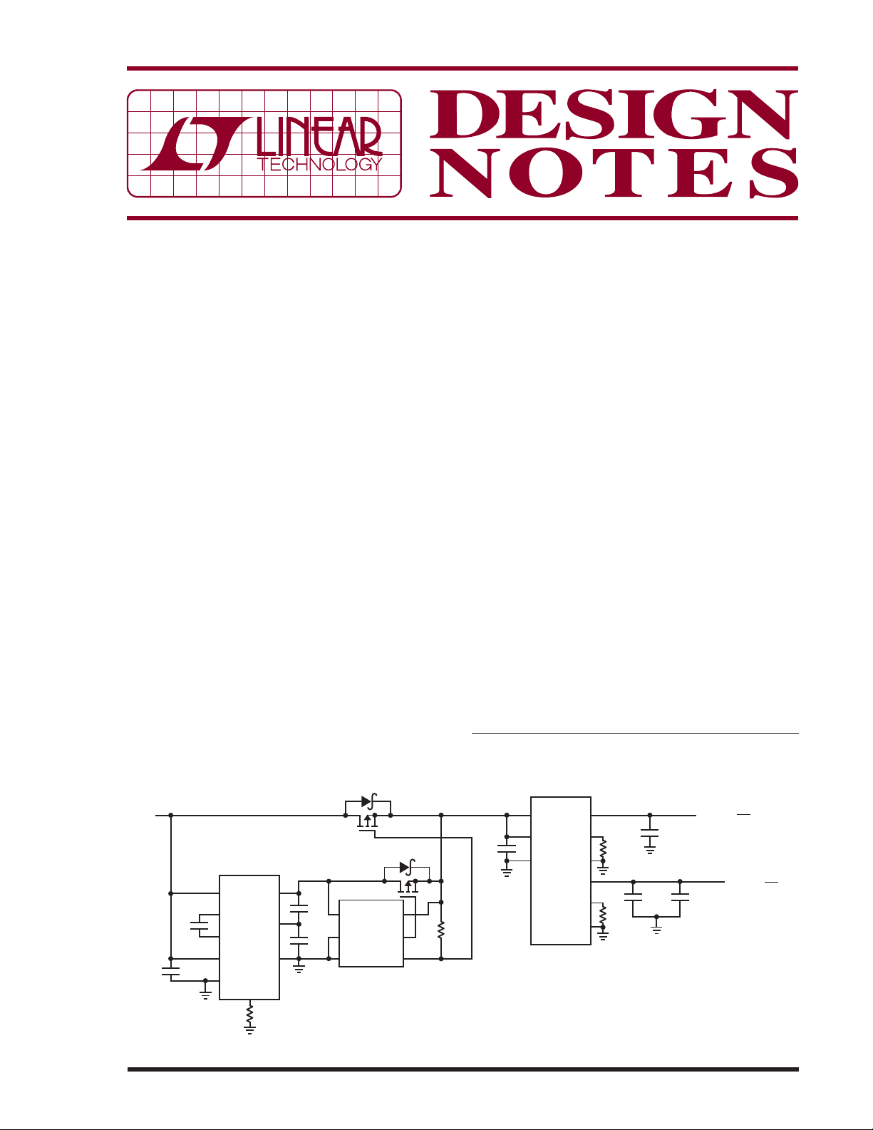
Figure 1 shows a 5V power ride-through application
where two series-connected 10F, 2.7V supercapacitors
charged to 4.8V can support 20W for over a second. The
LTC3225, a new charge-pump-based supercapacitor
charger, is used to charge the supercapacitors at 150mA
and maintain cell balancing while the LTC4412 provides
automatic switchover between the supercapacitor and
the main supply. The LTM4616 dual output DC/DC
TM
μModule
regulator creates the 1.8V and 1.2V outputs.
With a 20W load, the output volt ages remain in regulation
for 1.42 seconds after the main power is removed.
Q2
Si4421DY
5V
Q1
Si4421DY
LTC3225
V
C
IN
2.2μF
OUT
+
C1
1μF
C4
C
–
C
SHDN
V
SEL
PROG
R1
12k
CX
GND
C2
10F
2.7V
C3
10F
2.7V
V
GND
CTL
IN
LTC4412
SENSE
GATE
STAT
R2
470k
Supercapacitor Characteristics
A 10F, 2.7V supercapacitor is available in a 10mm ×
30mm 2-terminal radial can with an ESR of 25mΩ. One
advantage supercapacitors offer over batteries is their
long lifetime. A capacitor’s cycle life is quoted as greater
than 500,000 cycles, whereas batteries are specifi ed for
only a few hundred cycles. This makes the supercapacitor an ideal “set and forget” device, requiring little or no
maintenance.
Two critical parameters of a supercapacitor in any application are cell voltage and initial leakage current. Initial
leakage current is really dielectric absorption current,
which disappears after some time. The manufacturers
of supercapacitors rate their leakage current after 100
hours of applied voltage while the initial leakage current
in those fi rst 100 hours may be as much as 50 times the
specifi ed leakage current.
The voltage across the capacitor has a signifi cant effect
on its operating life. When used in series, the supercapacitors must have balanced cell voltages to prevent
overcharging of one of the series capacitors. Passive cell
L, LT, LTC and LTM are registered trademarks of Linear Technology Corporation.
μModule is a trademark of Linear Technology Corporation. All other trademarks are
the property of their respective owners.
22μF
LTM4616
V
V
IN1
OUT1
V
FB1
GND
IN2
ITHM1
V
ITHM2
C5
OUT2
FB2
R3
4.78k
R4
10k
C7
100μF
C6
100μF
C8
100μF
1.8V
=
V
OUT1
I
= 7A
O1
1.2V
V
=
OUT2
I
= 6A
O2
09/08/450
Figure 1. 5V Ride-Through Application Circuit Delivers 20W for 1.42 seconds
balancing, where a re sistor is placed across the capacitor,
is a popular and simple technique. The disadvantage of
this technique is that the capacitor discharges through the
balancing resistor when the charging circuit is disabled.
The rule of thumb for this scheme is to set the balancing resistor to 50 times the worst case leakage current,
estimated at 2μA/Farad. Given these parameters, a 10F,
2.5V superc apacitor would require a 2.5k bal ancing resistor. This resistor would drain 1mA of current from the
supercapacitor when the charging circuit is disabled.
A better alternative is to use a non-dissipative active cell
balancing circuit, such as the LTC3225, to maintain cell
voltage. The LTC3225 presents less than 4μA of load to
t h e s u p er c a p a c i t o r w h e n i n s h u t d ow n m o d e a n d l e s s t h a n
1μA when input power is removed. The LTC3225 featur es a
p r o g r a m m a b l e c h a r g i n g c u r r e n t o f u p t o 1 5 0 m A , c h a r g i n g
two series supercapacitors to either 4.8V or 5.3V while
balancing the individual capacitor voltages.
To provide a constant voltage to the load, a DC/DC converter is required between the load and the supercapacitor. As the voltage across the supercapacitor decreases,
the current drawn by the DC/DC converter increases to
maintain cons tant power to the load. The DC/ DC converter
drops out of regulation when its input voltage reaches
the minimum operating voltage (V
UV
).
To estimate the requirements for the supercapacitor, the
effective circuit resistance (R
is the sum of the capacitors’ ESRs plus the circuit
R
T
) needs to be determined.
T
distribution resistances, as follows:
RESRR
=+
TDIST
Assuming 10% of the input power is lost in the effective
circuit resistance when the DC/DC converter is at the
minimum operating voltage, the worst case R
2
V
.•
01
UV
P
IN
R
TMAX
()
=
T
is:
The voltage required across the supercapacitor at the
minimum operating voltage of the DC/DC converter is:
2
VPR
V
CUV
()
UV IN T
=
•
+
V
UV
The required effective capacitance can then be calculated
based on the required ride-through time (T
voltage on the capacitor (V
••
PT
2
C
=
EFF
IN RT
22
VV
−
CCUV
0
() ( )
C(0)
) and V
), an d the init ial
RT
shown by:
C(UV)
The effective capacitance of a series-connected bank of
capacitor s is the effective c apacitance of a single cap acitor
divided by the number of capacitors while the total ESR
is the sum of all the series ESRs.
The ESR of a supercapacitor decreases with increasing
frequency. Manufacturers usually specify the ESR at 1kHz,
while some manufac turers publish both the value at DC and
at 1kHz. The capacit ance of supercapacitor s also decreases
as frequency increases and is usually specifi ed at DC.
The capacitance at 1kHz is about 10% of the value at DC.
When using a supercapacitor in a ride-through application
where the power is being sourced for seconds to minutes,
use the effective capacitance and ESR measurements at
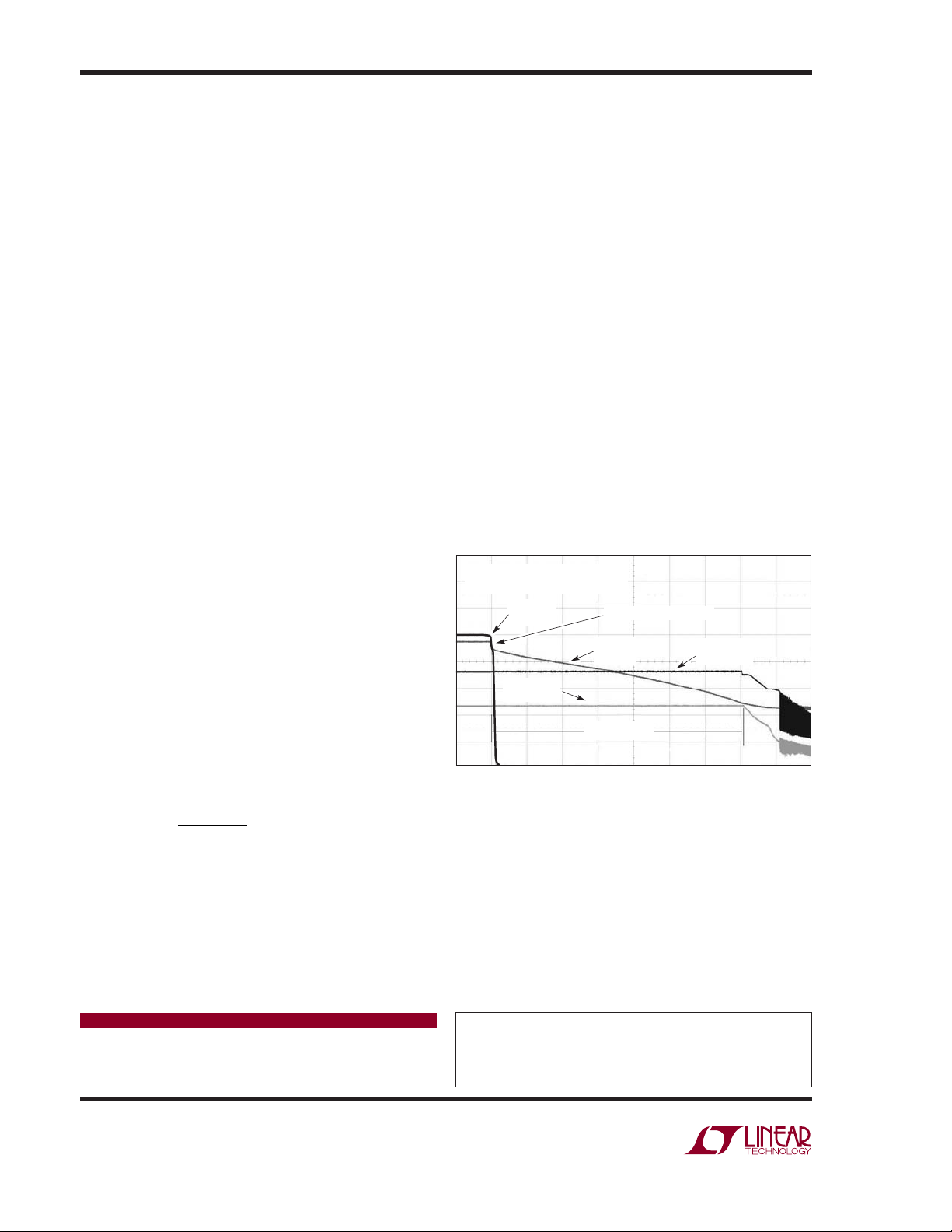
a low frequency, such at 0.3Hz. Figure 2 shows the ESR
effect manifested as a 180mV drop in voltage when input
power is removed.
5V SUPERCAPACITOR RIDE-THROUGH
V
IN
= 5V, V
= 4.8V, POWER = 20W
CAP
5V INPUT
(1V/DIV)
1.2V OUTPUT
(500mV/DIV)
Figure 2. 5V Ride-Through Application Timing
180mV STEP DUE TO ESR
V
CAP
(1V/DIV)
1.42 SECONDS
800ms/DIV
1.8V OUTPUT
(500mV/DIV)
Conclusion
Supercapaci tors can meet the needs of power r ide-through
applications where the time requirements are in the
seconds to minutes range. Supercapacitors offer long
life, low maintenance, light weight and environmentally
friendly solutions when compared to batteries. To this
end, the LTC3225 provides a compact, low noise solution for charging and cell balancing series-connected
supercapacitors, without degrading performance.
Data Sheet Download
www.linear.com
Linear Technology Corporation
1630 McCarthy Blvd., Milpitas, CA 95035-7417
(408) 432-1900
●
FAX: (408) 434-0507 ● www.linear.com
For applications help,
call (978) 656-3768
dn450 LT/TP 0908 246K • PRINTED IN THE USA
© LINEAR TECHNOLOGY CORPORATION 2007
 Loading...