

Tiny 2-Cell Solar Panel Charges Batteries in Compact,
Off-Grid Devices
Design Note 491
Fran Hoffart
Introduction
Advances in low power electronics now allow placement
of bat tery-powered sensors a nd other devices in locatio ns
far from the power grid. Ide ally, for true grid independen ce,
the batteries should not need replacement, but instead be
recharged using locally available renewable energy, such
as solar power. This Design Note shows how to produce
a compact battery charger that operates from a small
2-cell solar panel. A unique feature of this design is that
the DC/DC converter uses power point control to extract
maximum power from the solar panel.
The Importance of Maximum Power Point Control
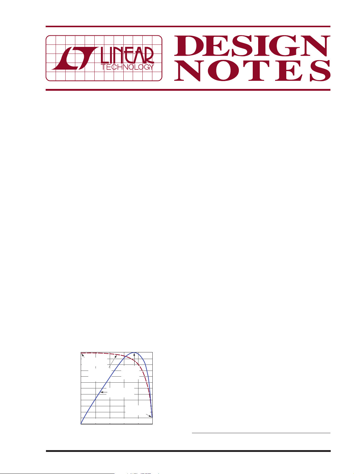
Although solar cells or solar panels are rated by power
output, a panel’s available power is hardly constant. Its
output power dep ends heavily on illumination, t emperature
and on the load current drawn from the panel. To illustrate
this, Figure 1 shows the V-I characteristic of a 2-cell solar
panel at a const ant illumination. The I-vs-V curve features
a relatively constant-current characteristic from shortcircuit (at the far left) to around 550mA load current, at
which point it bends to a constant-voltage characteristic
at lower currents, approaching maximum voltage at open
circuit (far right). The panel’s power output curve shows
a clear peak in power output around 750mV/530mA, at
the knee of the I-vs-V curve. If the load current increases
600
SHORT-CIRCUIT
CURRENT
500
SOLAR PANEL
400
300
200
100
SOLAR PANEL OUTPUT CURRENT (mA)
OUTPUT
CURRENT
2 SERIES POLYCRYSTALLINE CELLS
0
SOLAR PANEL OUTPUT VOLTAGE (mV)
MAXIMUM
POWER
POINT
SOLAR PANEL
OUTPUT POWER
OPEN-CIRCUIT
VOLTAGE
Figure 1. Solar Panel Output Voltage, Current and Power
06/11/491
400
SOLAR PANEL OUTPUT POWER (mW)
300
200
100
0
10008006004002000
DN F01
beyond the power peak, the power curve quickly drops
to zero (far left). Likewise, light loads push power toward
zero (far right), but this tends to be less of an issue.
Of course, panel illumination affects available power—
less light means lower power output; more light, more
power. Although illumination directly affects the
value
of peak power output, it does not do much to affect the
peak’s
location
on the voltage scale. That is, regardless
of illumination, the panel output voltage at which peak
power occurs remains relatively constant. Thus, it makes
sense to moderate the output current so that the solar
panel volt age remains at or above this peak power volt age,
in this case 750mV. Doing so is called maximum power
point control (MPPC).
Figure 2 shows the effects of varying sunlight on the
charge current, with maximum power point control and
without. T he simulated sunlight is varied from 100% down
to approximately 20%, then back up to 100%. Note that as
the sunlight intensity drops about 20%, the solar panel’s
output voltage and current also drop, but the LTC3105
maximum power point control prevents the panel’s
output voltage from dropping below the programmed
750mV. It accomplishes this by reducing the LTC3105
output charge current to prevent the solar panel from
collapsing to near zero volts, as is shown in the plot on
the right side of Figure 2. Without power point control,
a small reduction in sunlight can completely stop charge
current from flowing.
LTC3105 Boost Converter with Input Power Control
The LTC3105 is a synchronous step-up DC/DC converter
designed primarily to convert power from ambient energy
sources, such as low vol tage solar cells and thermoele ctric
generators, to battery charging power. The LTC3105 uses
MPPC to deliver ma ximum available power from the source.
It accomplishes this by reducing the LTC3105 output current to prevent the solar panel from collapsing to near zero
L, LT, LTC, LTM, Linear Technology, the Linear logo and Burst Mode are registered
trademarks of Linear Technology Corporation. All other trademarks are the property of
their respective owners.

600
400
100% 100%
200
PANEL
OUTPUT (mA)
0
60
LTC3105
40
CHARGE
CURRENT
20
CHARGE
BATTERY VOLTAGE = 3.6V
CURRENT (mA)
0
(WITH MAXIMUM POWER POINT CONTROL)
SOLAR PANEL
OUTPUT CURRENT
RELATIVE SUNLIGHT
INTENSITY
10 SECONDS
Figure 2. Changing Sunlight Intensity Effects on Charge Current
SOLAR PANEL
OUTPUT VOLTAGE
SOLAR PANEL OUTPUT (V)
1.0
0.8
0.6
0.4
0.2
0
600
400
100%
200
PANEL
OUTPUT (mA)
0
60
LTC3105
40
CHARGE
CURRENT
20
CHARGE
CURRENT (mA)
0
SOLAR PANEL
OUTPUT CURRENT
RELATIVE SUNLIGHT
INTENSITY
SOLAR PANEL
OUTPUT VOLTAGE
BATTERY
VOLT. = 3.6V
(NO MAXIMUM POWER POINT CONTROL)
10 SECONDS
100%
LTC3105
CHARGE
CURRENT
SOLAR PANEL OUTPUT (V)
1.0
0.8
0.6
0.4
0.2
0
DN F02
volts. The LTC3105 is capable of starting up with an input
as low as 250mV, allowing it to be powered by a single
solar cell or up to nine or ten series-connected cells.
Output disconnect eliminates the isolation diode often
required with other solar powered DC/DC converters
and allows the output voltage to be above or below the
input voltage. The 400mA switch current limit is reduced
during start-up to allow operation from relatively high
impedance power sources, but still provides sufficient
power for many low power solar applications once the
converter is in normal operation. Also included are a 6mA
adjustable ou tput low dropout linear regulator, open-drain
power good output, shutdown input and Burst Mode
®
operation to improve ef ficiency in low power applications.
Solar-Powered Li-Ion Battery Charger
Figure 3 shows a compact solar-powered battery charger
using a LTC3105 as a boost converter and a LTC4071 as a
Li-Ion shunt charger. A 2-cell 400mW solar pan el provides
the input power to the LTC3105 to produce over 60mA
of charge current in full sunlight. Maximum power point
control prevents the solar panel voltage from dropping
below the 750mV maximum power point, as shown in
Figure 1. The converter’s output voltage is programmed
for 4.35V, slightly above the 4.2V float voltage of the
Li-Ion battery. The LTC4071 shunt charger limits the
voltage across the battery to 4.2V. Grounding the FBLDO
pin programs the low dropout regulator to 2.2V, which
powers the “charging” LED. This LED is on when charging
and off when the battery voltage is within 40mV of the
float voltage, indicating near full charge. An NTC thermistor senses battery temperature and lowers the LTC4071
float voltage at high ambient temperatures for increased
battery safety. To prevent battery damage from overdischarge, the low bat tery disconnec t feature disconnects
the battery from the load if the battery drops below 2.7V.
Conclusion
Although the circuit described here produces only a
few hundred milliwatts, it can provide enough power to
keep a 400mAhr Li-Ion battery fully charged under most
weather conditions. The low input voltage, combined
with input power control, makes the LTC3105 ideal for
low power solar applications. In addition, the LTC4071
shunt charging system complements the LTC3105 by
providing the precision float voltage, charge status and
temperature safety features to assure long battery life in
outdoor environments.
SOLAR PANEL
(2 CELLS)
ISC = 600mA,
VOC = 1V
MPPC
OPTIONAL MPPC
TEMPERATURE TRACKING,
SEE DATA SHEET FOR DETAILS
+
–
10µH
10µF
75k
ONOFF
1µF
Figure 3. 2-Cell Solar Panel Li-Ion Battery Charger
Data Sheet Download
www.linear.com
Linear Technology Corporation
1630 McCarthy Blvd., Milpitas, CA 95035-7417
(408) 432-1900
●
FAX: (408) 434-0507 ● www.linear.com
SW
IN
MPPC
SHDN
AUX
LTC3105
PGOOD
GND
OUT
LDO
FBLDO
1M
FB
2.2V
10µF
301k
220Ω
CHARGING
LED STATUS
ON = CHARGING
OFF = V
BAT
OFF = NO BATTERY OR NO V
ADJ
LBSEL
LTC4071
LED
HBO
APPROACHES V
V
BAT
NTC BIAS
NTC
GND
FLOAT
IN
4.2V
+
LOAD
400mAhr
Li-Ion
POLYMER
BATTERY
DN F03
CC
10k
NTC
10k
For applications help,
call (408) 432-1900, Ext. 3725
dn491 LT/AP 0611 226K • PRINTED IN THE USA
LINEAR TECHNOLOGY CORPORATION 2011
 Loading...