

advertisement
Power Supply Sequencing Made Simple – Design Note 401
Bob Jurgilewicz
Introduction
System designers face a number of problems when it
comes to controlling multiple power supplies. Turn-on
and turn-off characteristics, supply monitoring, fault
management and reset generation are a few issues that
affect both the short term system performance and
long-term reliability. Design is further complicated by
a process that often puts fi nal decisions about supply
requirements at the end of the design phase. So, a good
supervisor/control solution allows for easy design and
adjustment anywhere in the design process.
Firmware solutions place a daunting hurdle directly in
the critical path of the design. Every change involves
software engineers, a load of testing and worst of all,
w a it i ng . L o ad in g co de d ur i n g p r od u c t io n i s ti m e c o n su m ing and costly.
A better solution uses hardware, but easy-to-change,
relatively inexpensive hardware. How about generic reusable circuit blocks that are added early in the system
d e s i g n w i t h l i t t l e r e g a r d t o t h e fi nal specifi c power requir ements? The existing blocks are left unfi nished, simply
waiting for passive component values to be determined.
When fi nal decisions about the power supplies’ operating
specifi cations are determined, calculate the values for a
few passive components and populate the empty spaces
in the circuit. Fortunately, such a solution exists.
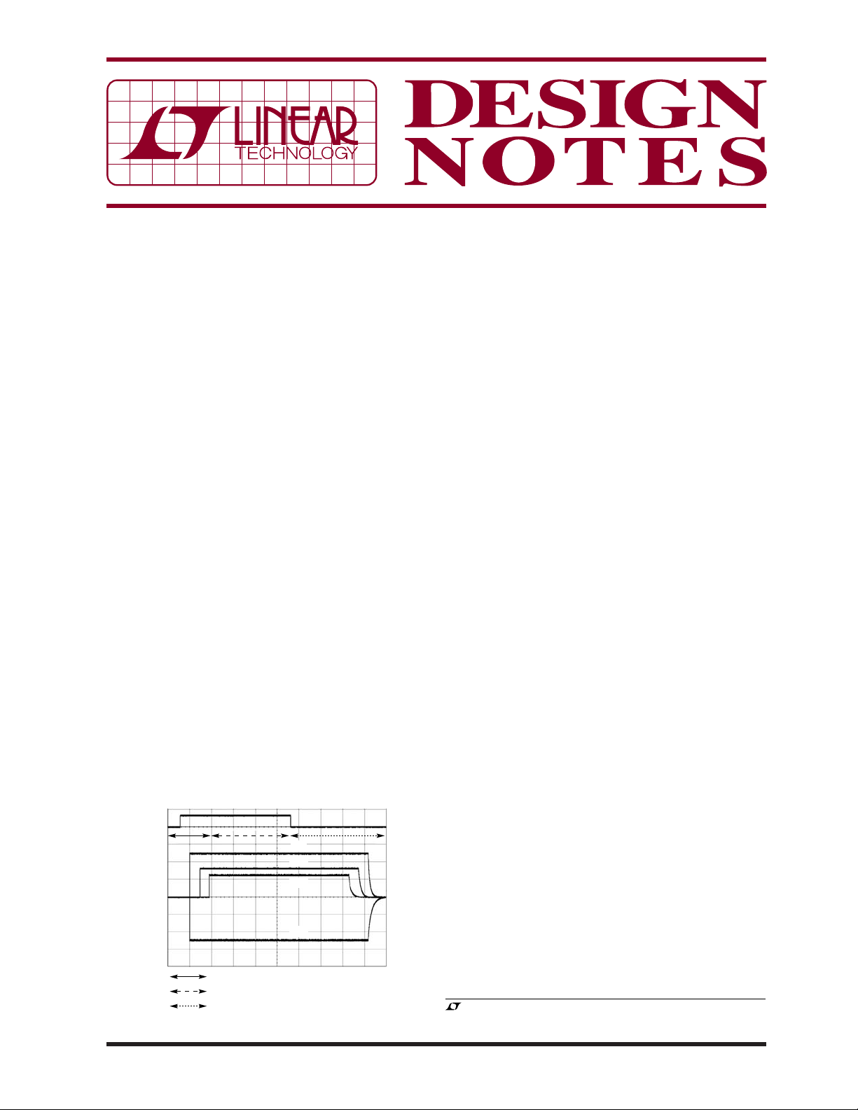
ON
5V
3.3V
2.5V
–5V
SEQUENCE-UP PHASE
SUPPLY MONITOR PHASE
SEQUENCE-DOWN PHASE
Figure 1. Sequencing Application Waveforms
The LTC2928 is a 4-channel cascadable power supply sequencer and high accuracy supervisor. Multiple
LTC2928s can be easily connected to sequence an
unlimited number of power supplies. Cascade action is
via a single pin connection and is functional during sequence-up and sequence-down operations. Sequencing
thresholds, order and timing are confi gured with just a
few external components, eliminating the need for PC
board layout or software changes during system development. Sequence outputs control supply enable pins
or N-channel pass gates. Precision input comparators
with individual outputs monitor power supply voltages
to 1.5% accuracy. Supervisory functions include under
and overvoltage monitoring and reporting as well as
reset generation. The reset output may be forced high
to complement margin testing.
Application faults, whether generated by the LTC2928 or
communicated by a host, can shut down all controlled
supplies. The type and source of faults are reported for
diagnosis. Individual channel controls are available to
independently exercise enable outputs and supervisory
functions. A high voltage input allows the LTC2928 to be
powered from voltages as high as 16.5V. A buffered reference output permits negative power supply sequencing
and monitoring operations.
Three Phases of the Power Management Cycle
A complete power management c ycle is divided in to three
phases as shown in Figure 1. The sequence-up phase
initiates by transitioning the ON pin above threshold with
a logic signal or power supply. The controlled supplies
sequence-up with user confi gured order and timing.
All supplies must exceed a user defi ned sequence-up
threshold within the confi gured “power-good” time. If
any supply fails to turn on properly, a sequence fault
occurs and all controlled supplies are shut down. Once
all supplies reach their sequence-up thre shold, the supply
monitor phase begins.
, LT, LTC and LTM are registered trademarks of Linear Technology
Corporation. All other trademarks are the property of their respective owners.
10/06/401
12V
1/2 LTC1628
V
IN
V
RUN
OUT
5V
LTM4600
V
V
IN
OUT
RUN
1/2 LTC1628
V
V
IN
OUT
RUN
LTC3704
V
V
IN
OUT
RUN
µF
0.1
ON
95.3k
42.2k
24.3k
95.3k
3.32k
V
CC
1µF
ALL RESISTORS 1%
EN1HV
CC
ON
RT1
RT2
RT3
RT4
DONE
SQT1
SQT2
VSEL
V
CC
GND MS1 MS2
EN2 EN4EN3 REF
LTC2928
RTMR
PTMR STMR
47nF 6.8nF
0.15µF
20.5k
OVA
RST
FLT
80.6k
54.9k 42.2k 88.7k
V1
V2
V3
V4
OV
10.7k
60.4k
10k 10k
11.5k
SYSTEM
RESET
FAULT
V
CC
2.5V
3.3V
–5V
10.7k
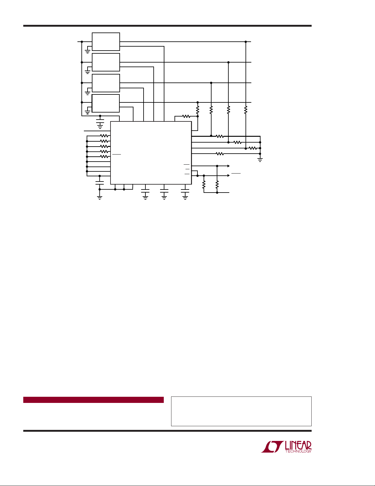
DN401 F02
Figure 2. LTC2928 Application Schematic (component values calculated with the LTC2928 Confi gurator Tool)
During the supply monitor pha se, the input signals are continuously compared against user c onfi gured undervoltage
and overvoltage thresholds. The comparators fi lter out
minor glitches coupled to their inputs. If any supply is
out of compliance with suffi cient magnitude and dura-
⎯R⎯S⎯
tion, the reset output (
⎯O⎯
V) pulls low. Once all inputs are within compliance,
(
T) and/or overvoltage output
the respective monitor output pulls high after the user
defi ned reset delay. Users may select whether or not a
fault is generated on the basis of under or overvoltage
events. A generated fault shuts down all controlled supplies. Shut ting down upon an under voltage fault is often
a critical operation. For example, consider a temporary
short on one supply due to a probe slip. Once the short
is removed, the supply may recover, but it might do so
out of sequence if the other supplies are unaffected. A
reset fault shuts off all the supplies, allowing for a new
in-sequence start-up procedure.
The sequence-down phase initiates by transitioning the
ON pin below threshold with a logic signal or power
supply. The controlled supplies sequence-down with
user confi gured order and timing. All supplies must fall
below the user defi ned sequence-down threshold within
the confi gured “power-good” time. If any supply fails to
turn off pr operly, a sequence f ault occurs and all controll ed
supplies are shut down.
LTC2928 Confi guration Software Designs It for You
To make life truly simple, Linear Technology offers free
confi guration software that calculates all resistor values,
capacitor values and required logic connections. The
tool also generates schematics and a passive element
bill-of-materials. All you need to know are your supply
parameters and sequence order. Contact Linear Technology for details.
Conclusion
The LTC2928 greatly reduces the time and cost of power
management design by eliminating the need to develop,
verify and load fi rmware at back end test. System control
issues such as sequence order, timing, reset generation,
supply monitoring and fault management are all handled
with the LTC2928.
Data Sheet Download
www.linear.com
Linear Technology Corporation
1630 McCarthy Blvd., Milpitas, CA 95035-7417
(408) 432-1900
●
FAX: (408) 434-0507 ● www.linear.com
For applications help,
call (408) 432-1900, Ext. 2452
dn401f LT 1006 409K • PRINTED IN THE USA
© LINEAR TECHNOLOGY CORPORATION 2006
 Loading...