


advertisement
Versatile Voltage Monitors Simplify Detection of Overvoltage
and Undervoltage Faults – Design Note 408
Scott Jackson
Introduction
Many modern electronic systems have strict power supply
operating ranges —requiring accurate monitoring of each
supply. Some systems must know that all supplies are
present and stable before startup and some must know
if the supplies deviate from safe operating conditions.
®
The LTC
2912, LTC2913, and LTC2914 supervisors
respectively monitor single, dual, and quad power supplies for undervoltage and overvoltage with tight 1.5%
threshold accuracy over temperature. All monitors in the
multiple-monitor devices share a common undervoltage
output and a common overvoltage output with a timeout
period that is adjustable or disabled. Each monitor has
input glitch rejection to ensure reliable reset operation
without false or noisy triggering.
Each part has at least two options: one with capability
to latch the overvoltage output and one with capability
5V
P0WER
SUPPLIES
3.3V
2.5V
1.8V
to externally disable both outputs. The LTC2912 has a
third option with latching capability and a non-inverted
overvoltage output. Each part has an internal 6.5V shunt
regulator allowing the device to be used in a system with
any supply level.
Basic Operation
Figure 1 shows a t ypical application for the LTC2914. Each
monitored input is compared to a 0.5V threshold. Any
channel can be confi gured to monitor both undervoltage
and overvoltage conditions using a 3-resistor divider.
When monitoring a positive voltage, the VH input of the
channel is connected to the high-side tap of the resistive
divider and triggers an undervoltage condition while the
VL input is connected to the low-side tap of the resistive
divider and triggers an overvoltage condition. When an
, LT, LTC and LTM are registered trademarks of Linear Technology Corporation.
ThinSOT is a trademark of Linear Technology Corporation.
All other trademarks are the property of their respective owners.
0.1µF
02/07/408
44.2k
4.53k
27.4k1k
1k
19.6k4.53k
12.4k1k
4.53k
1k
4.53k
V
CC
VH1
VL1
VH2
LTC2914-1
VL2
REF
VH3
VL3
VH4
VL4
GND TMR
SEL
LATCH
OV
UV
C
TMR
22nF
Figure 1. Quad UV/OV Supply Monitor
SYSTEM
DN408 F01
TIMEOUT = 200ms
undervoltage condition is detected, the
⎯U⎯
V output as-
serts low.
Once all undervoltage conditions clear, the
⎯U⎯V output
remains asserted until a timeout period has elapsed.
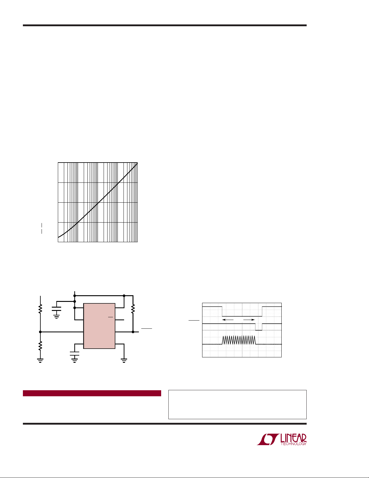
This timeout period is set by a capacitor between the
TMR and GND pins. The timeout period can be disabled
by tying the TMR pin to V
period versus TMR capacitance. The
. Figure 2 shows the timeout
CC
⎯O⎯V output behaves
in a similar manner. On parts with latching capability,
⎯O⎯V output latches when asserted until cleared by
the
the
⎯L⎯A⎯T⎯C⎯H pin. Holding the ⎯L⎯A⎯T⎯C⎯H pin high bypasses
the overvoltage latch.
Minimum Fault Length Monitor
The LTC2912-3 can be used to detect an undervoltage
condition with a minimum duration by using the VL input
10000
(ms)
1000
UOTO
100
10
UV/OV TIMEOUT PERIOD, t
1
0.1 10 100 1000
Figure 2. Timeout Period vs Capacitance
1
TMR PIN CAPACITANCE, C
TMR
(nF)
DN408 F02
and the non-inver ted OV output. For example, an automobile system may need to monitor the 12V power supply
during a power up condition. During the initial cranking
of the automobile, the power supply droops. If the supply droop exists for an extended period, the system may
need to disconnect various circuits from the supply for
protection or disc onnect circuit s to reduce the loa d. This
is accomplished by the circuit shown in Figure 3.
The timeout func tion of the LTC2912 typically s tarts when
a fault clears. However, because the VL input is used
in this case to monitor an undervoltage instead of an
overvolt age, the timeout function occurs at the beginning
of an undervoltage condition and the OV output remains
high until the period has elapsed. If the fault still exists
when this timeout period elapses, the OV output (
⎯F⎯A⎯U⎯L⎯T)
pulls low until the fault clears. Choosing a 0.47µF timing
capacitor produces a 4.1s timeout delay. Therefore, any
supply droop lower than 9.6V and longer than 4.1s asserts FAULT. Figure 4 shows the resulting waveform of
a supply fault condition of 9V for 5 seconds.
Conclusion
The LTC2912, LTC2913, and LTC2914 simplify power
supply monitoring of any voltage level by offering superior performance and fl exibility. Only a few resistors
are needed to confi gure monitoring of multiple voltages
for both undervoltage and overvoltage conditions. The
LTC2914 offers these features in a 16-lead SSOP and
16-lead (5mm × 3mm) DFN package, the LTC2913 in a
10-lead MSOP and 10-lead (3mm × 3mm) DFN package,
TM
and the LTC2912 in a tiny 8-lead ThinSOT
and 8-lead
(3mm × 2mm) DFN package.
V
MONITOR
12V
9.6V FAULT
R
B
10k
R
A
549k
C
BYP
0.1µF
V
CC
5V
LATCH
V
CC
VH
VL
TMR
C
TMR
0.47µF
T
FAULT
LTC2912-3
UV
OV
GND
DN408 F03
= 4.1s
Figure 3. Fault Detection Circuit for a 4.1s
Undervoltage Condition
Data Sheet Download
www.linear.com
Linear Technology Corporation
1630 McCarthy Blvd., Milpitas, CA 95035-7417
(408) 432-1900
●
FAX: (408) 434-0507 ● www.linear.com
R
10k
OV
FAULT
V
MONITOR
FAULT
4.1s
TMR
1s/DIV
12V
9V
5V
0V
DN408 F04
Figure 4. Fault Detection Waveform of
a 4.1s Undervoltage Condition
For applications help,
call (408) 432-1900, Ext. 2452
dn408f LT 0207 305K • PRINTED IN THE USA
© LINEAR TECHNOLOGY CORPORATION 2007
 Loading...