

advertisement
Easy Drive™ ADCs Simplify Measurement of
High Impedance Sensors – Design Note 379
Mark Thoren
Delta-si gma ADCs, with their high accuracy a nd high noise
immunity, are ideal for directly measuring many types
of sensors. Nevertheless, input sampling currents can
overwhelm high source impedances or low-bandwidth,
®
micropower signal conditioning circuits. The LTC
2484
family of delta sigma converters solves this problem by
balancing the input currents, thus simplif ying or eliminating the need for signal conditioning circuits.
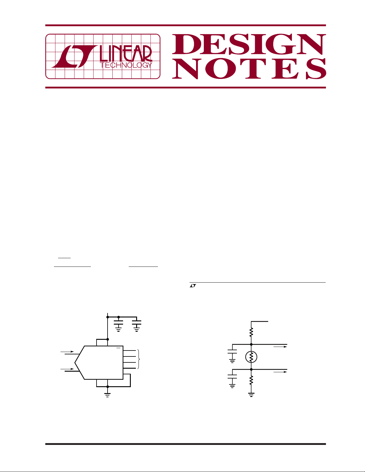
A common applicat ion for a delta-sigma ADC is thermis tor
measurement. Figure 1 shows the LTC2484 connections
for direct measurement of thermistors up to 100kΩ. Data
I/O is through a standard SPI interface and the sampling
current in each input is approximately:
V
⎛
⎞
REF
–
V
⎜
⎝
2
15 2
or about 1.67μA when V
CM
⎟
⎠
.
M
Ω
,
where V
CM
REF
+
–
+
VV
IN IN
=
is 5V and both inputs
are grounded.
5V
6
9
7
1
10
C7
0.1µF
4-WIRE
SPI INTERFACE
C8
1µF
IN
IN
+
–
32
REF
V
LTC2484
GND
GND
CC
CS
SCK
SDO
SDI
F
O
118
+
–
= I
I
IN
IN
4
5
Figure 2 shows how to balance the thermistor such
that the ADC input current is minimized. If reference
resistors R1 and R4 are exactly equal, the input current
is zero and no errors result. If the reference resistors
have a 1% tolerance, the maximum error in the measured
resistance is 1.6Ω due to the slight shift in common mode
voltage; far less than the 1% error of the reference resistors themselves. No amplifi er i s r equir ed, making this an
ideal solution in micropower applications.
It may be necessary to ground one side of the sensor to
reduce noise pickup or simplify wiring if the sensor is
remote. The varying common mode voltage produces a
3.5kΩ full-scale error in the measured resistance if this
circuit is used without buffering.
Figure 3 shows how to interface a very low power, low
®
bandwidth op amp to the LTC2484. The LT
1494 has
excellent DC specs for an amplifi er with 1.5µA supply
, LTC and LT are registered trademarks and Easy Drive is a trademark of Linear
Technology Corporation. All other trademarks are the property of their respective
owners.
5V
R1
51.1k
+
TO IN
+
I
= 0
IN
–
TO IN
–
= 0
I
IN
0.1µF
0.1µF
C4
C3
R3
10k-100k
R4
51.1k
12/05/379
Figure 1. LTC2484 Connections
DN379 FO1
DN379 FO2
Figure 2. Centered Sensor
current—the maximum offset voltage is 150µV and
the open loop gain is 100,000—but its 2kHz bandwidth
makes it unsuitable for driving conventional delta-sigma
ADCs. Adding a 1kΩ, 0.1µF fi lter solves this problem by
providing a charge reservoir that supplies the LTC2484’s
instantaneous sampling current, while the 1kΩ resistor
isolates the capacitive load from the LT1494. Don’t try this
5V
with an ordinary delta-sigma ADC—the sampling current
from ADCs with specifi cations similar to the LTC2484
family would result in a 1.4mV offset and a 0.69mV
full-scale error in the circuit shown in Figure 3. The
LTC2484’s balanced input current allows these errors to
–
be easily cancelled by placing an identical fi lter at IN
.
102k
10k-100k
0.1µF
+
–
5V
LT1497
1k
0.1µF
1k
0.1µF
DN379 F03
TO IN
TO IN
+
–
DN379 FO4
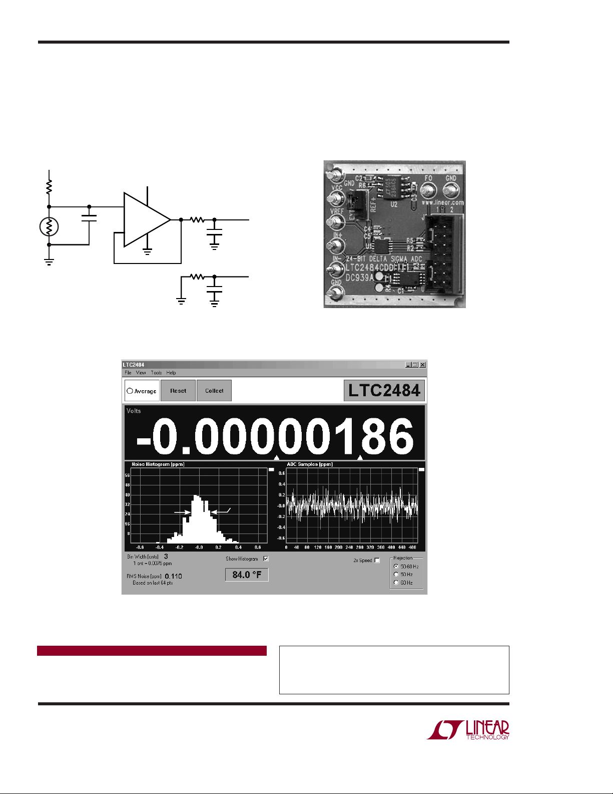
Figure 4. LTC2484 Demo BoardFigure 3. Grounded, Buffered Sensor
Figure 5. LTC2484 Demo Software Screenshot Showing Microvolt Offset and 600nV
Data Sheet Download
http://www.linear.com
Linear Technology Corporation
1630 McCarthy Blvd., Milpitas, CA 95035-7417
(408) 432-1900
●
FAX: (408) 434-0507 ● www.linear.com
600nV
RMS
DN379 FO5
Noise
RMS
For applications help,
call (408) 432-1900, Ext. 2453
dn379 LT/TP 1205 305K • PRINTED IN THE USA
© LINEAR TECHNOLOGY CORPORATION 2005
 Loading...