

6-Channel SAR ADCs for Industrial Monitoring and Portable
Instruments
Design Note 426
Guy Hoover and Steve Logan
The 14-bit LTC2351-14 is a 1.5Msps, low power SAR
ADC with six simultaneously sampled differential input
channels. It operate s from a single 3V supply and features
six independent sample-and-hold amplifi ers and a single
ADC. The single ADC w ith multiple S/HA s enables excellent
range match (1mV) between channels and channel-tochannel skew (200ps).
The versatile LTC2351-14 is ideally suited for industrial
monitoring applications such as 3-phase power line
monitoring to ensure line voltage compliance, portable
power line instrumentation, power factor correction, motor control, and data acquisition. These applications may
be battery powered, and it is here that the LTC2351-14’s
LT1790-1.25
IN OUT3V
120VAC
LINE
4 TURNS
CR MAGNETICS
CR8348-2500-N
6:1
0.1MF
100Ω
100Ω
2k
49.9Ω
49.9Ω
2k
GND
49.9Ω
47pF 47pF
49.9Ω
49.9Ω
47pF 47pF
49.9Ω
low power and small size are desirable. Power consumption is a mere 16.5mW, which extends battery life. The
3-wire serial interface means fewer pins than parallel
output devices, allowing the LTC2351-14 to fi t in a 32-pin,
5mm × 5mm QFN package.
Power Line Monitoring Application
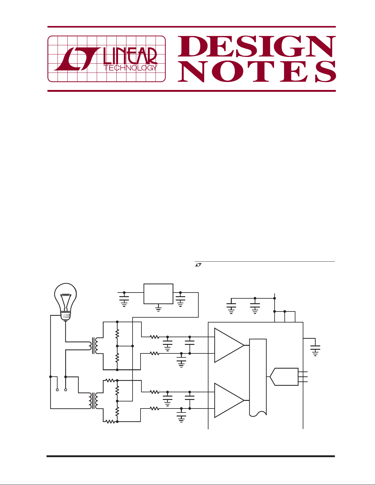
Figure 1 shows a t ypical power line monitoring applica tion.
Current is sensed by a CR Magnetics CR8348-2500-N
current transformer. An LT1790-1.25 biases the output
of the transformer to the middle of the LTC2351-14 input
range, giving the inputs maximum swing. A 6:1 transformer and 41:1 attenuator scale the line voltage, and the
transformer output is similarly biased.
, LT, LTC and LTM are registered trademarks of Linear Technology Corporation.
All other trademarks are the property of their respective owners.
3V
1MF
10MF
CH0
+
S&H
–
47pF
CH1
+
S&H
–
47pF
0.1MF
LTC2351-14
MUX
VCCV
14-BIT ADC
OV
DD
DD
V
REF
CONV
SCK
SDO
TO
PROCESSOR
10MF
10/07/426
CHANNELS 2-5 TO MEASURE TWO OTHER VI PAIRS
Figure 1. Typical Power Line Monitoring Application
DN426 F01
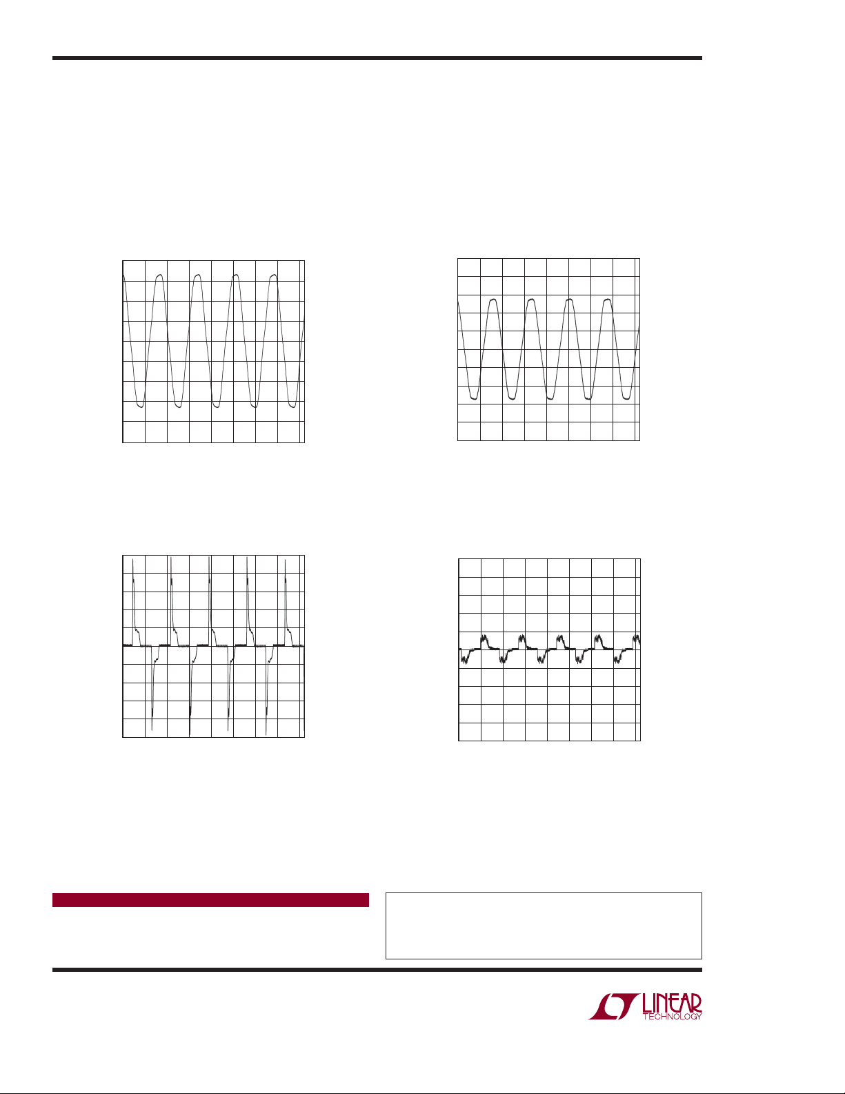
Figure 2 shows the AC line voltage in Linear Technology’s
Mixed Signal lab. The fl attened peaks are typical of
the voltage in an offi ce building where many of the
loads are nonlinear, such as computer power supplies.
Figure 3 shows the current through a 50W incandescent
bulb. Figure 4 shows the current through a 15W compact
fl uorescent bulb, and Figure 5 is the current through a 4W
LED-based bulb. The 5MHz full linear bandwidth of the
L T C 2 3 5 1 - 14 a l l o w s a n a l y s i s o f h i g h f r e q u e n c y c o m p o n e n t s
of the line voltage and current, limited in this case by the
bandwidth of the sense transformers.
Conclusion
With PCB real estate getting tighter and designers always
searching for lower power ICs, fast data acquisition can
be a challenge. The LTC2351-14 and other low power
SAR converters make it possible to optimize solution
size, power and cost.
200
150
100
50
0
–50
VOLTAGE (V)
–100
–150
–200
–250
0
10
30 40 6050 70
20
TIME (ms)
80
dn426 F02
1.0
0.8
0.6
0.4
0.2
0
–0.2
CURRENT (A)
–0.4
–0.6
–0.8
–1.0
0
10
30 40 6050 70
20
TIME (ms)
dn426 F03
Figure 2. Line Voltage Figure 3. 50W Incandescent Bulb Current
1.0
0.8
0.6
0.4
0.2
0
–0.2
CURRENT (A)
–0.4
–0.6
–0.8
–1.0
0
10
30 40 6050 70
20
TIME (ms)
80
dn426 F04
1.0
0.8
0.6
0.4
0.2
0
–0.2
CURRENT (A)
–0.4
–0.6
–0.8
–1.0
0
10
30 40 6050 70
20
TIME (ms)
dn426 F05
Figure 4. 15W Compact Fluorescent Bulb Current Figure 5. 4W LED Bulb Current
80
80
Data Sheet Download
www.linear.com
Linear Technology Corporation
1630 McCarthy Blvd., Milpitas, CA 95035-7417
(408) 432-1900
●
FAX: (408) 434-0507 ● www.linear.com
For applications help,
call (408) 432-1900, Ext. 2602
dn426f LT/TP 1007 305K • PRINTED IN THE USA
© LINEAR TECHNOLOGY CORPORATION 2007
 Loading...