

14-/12-Bit 150Msps
25Msps
40Msps
65Msps
80Msps
105Msps
125Msps
150Msps
35mW
Power
Consumption
49mW
81mW
89mW
106mW
127mW
1.8V Single ADCs, CMOS,
DDR CMOS or DDR LVDS Outputs
149mW
2256-14
2257-14
2258-14
2259-14
2260-14
2261-14
2262-14
2256-12
2257-12
2262-12
6x6
QFN
2258-12
2259-12
2260-12
2261-12
14-Bit
73.2dB SNR
12-Bit
70.6dB SNR
CLKOUT
CLKOUT
OF
D13/D0
D12/D0
•
•
•
D2/D0
D1/D0
D0
OF
D13
D12D2D1
D0
RANDOMIZER
ON
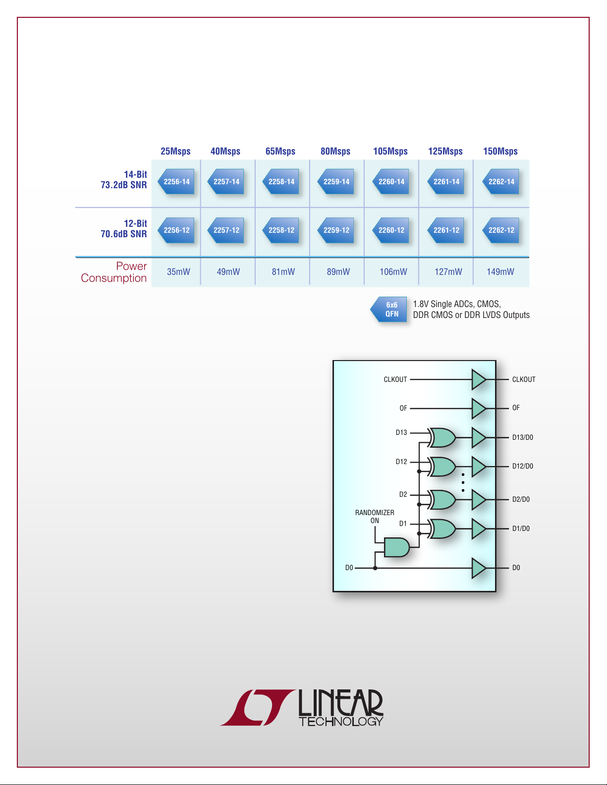
1.8V ADC Family
Features
n
Pin-Compatible Family of 14- /12-Bit,
25Msps to 150Msps ADCs
n
Single 1.8V Supply
n
Flexible Digital Interface:
CMOS, DDR CMOS or DDR LVDS
n
Selectable Input Ranges: 1V
n
800MHz Full-Power Bandwidth S/H
n
Optional Data Output Randomizer
n
Alternate Bit Polarity Mode
n
Optional Clock Duty Cycle Stabilizer
n
Shutdown and Nap Modes
n
Serial SPI Port for Configuration
n
Easy Evaluation Using PScope™ Tool
to 2V
P-P
P-P
Digital Output Randomizer Reduces
Digital Feedback
L, LT, LTC, LTM, Linear Technology and the Linear logo are registered
trademarks and PScope is a trademark of Linear Technology Corporation. All
other trademarks are the property of their respective owners.
Alternate Bit Polarity Mode
D13
D12
D11
D10
D9
D8
D7
D6
D5
D4
D3
D2
D1
D0
D13
D12
D11
D10
D9
D8
D7
D6
D5
D4
D3
D2
D1
D0
Encoded Data
LTC2262-14
FPGA or ASIC
DECODED
DATA
RAW
DATA
7×
7×
OUTPUT CODE
10 1010 1010 1001
10 1010 1010 1000
10 1010 1010 1011
10 1010 1010 1010
01 0101 0101 0101
01 0101 0101 0100
01 0101 0101 0111
7 Bits 0 to 1
7 Bits 1 to 0
at Mid-Scale
FREQUENCY (MHz)
0
–80
–90
–100
–110
–120
–130
–50
–60
–70
–40
–30
–20
–1001020304050
60
FREQUENCY (MHz)
0
–130
–80
–90
–100
–110
–120
–50
–60
–70
–40
–30
–20
–10
0102030405060
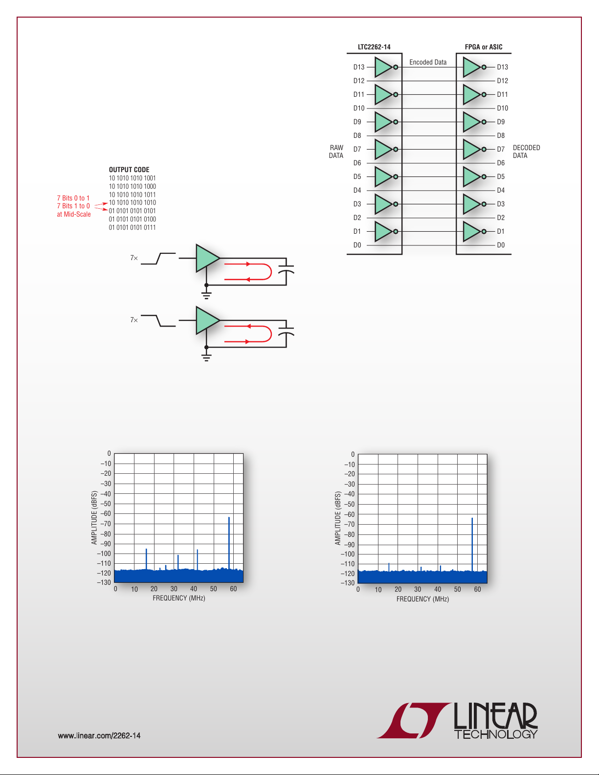
The LTC®2262 family offers a new, proprietary feature to
reduce digital feedback on the circuit board. The alternate
bit polarity mode inverts all of the odd bits before the
output buffers to equalize the number of ones and zeroes
switching. This method effectively cancels the large ground
plane currents that contribute to digital feedback when
sampling small input signals crossing mid-scale.
When alternate bit polarity (ABP) mode is enabled, all of the odd bits are inverted before the output buffers. The even bits are not
affected. This method can work in combination with the digital output randomizer to help reduce digital currents in the circuit board
ground plane that cause digital noise, particularly for very small analog input signals.
ABP = Off, RAND = Off
ABP = On, RAND = On
LTC2261-14, 125Msps, AIN = 70MHz, –65dBFS
Averaged 128k Point FFTs
www.linear.com/2262-14 n 1-800-4-LINEAR
0511
 Loading...