

Page 1
42V, 2.5A Synchronous Step-Down Regulator with 2.5µA
Quiescent Current
Design Note 504
Hua (Walker) Bai
Introduction
The LT®8610 and LT8611 are 42V, 2.5A synchronous
step-down regulators that meet the stringent high
input voltage and low output voltage requirements of
automotive, industrial and communications applications. To minimize external components and solution
size, the top and bottom power switches are integrated
in a synchronous regulator topology, including internal
compensation. The regulator consumes only 2.5μA
quiescent current from the input source even while
regulating the output.
High Effi ciency Synchonous Operation
Replacing an external Schottky diode with an internal
synchronous power swit ch not only minimizes the solution size, but also incre ases effi cienc y and reduces power
dissipation. The effi ciency improvement is signifi cant
in low output voltage applications where the voltage
drop of the Schottky diode represents a relatively large
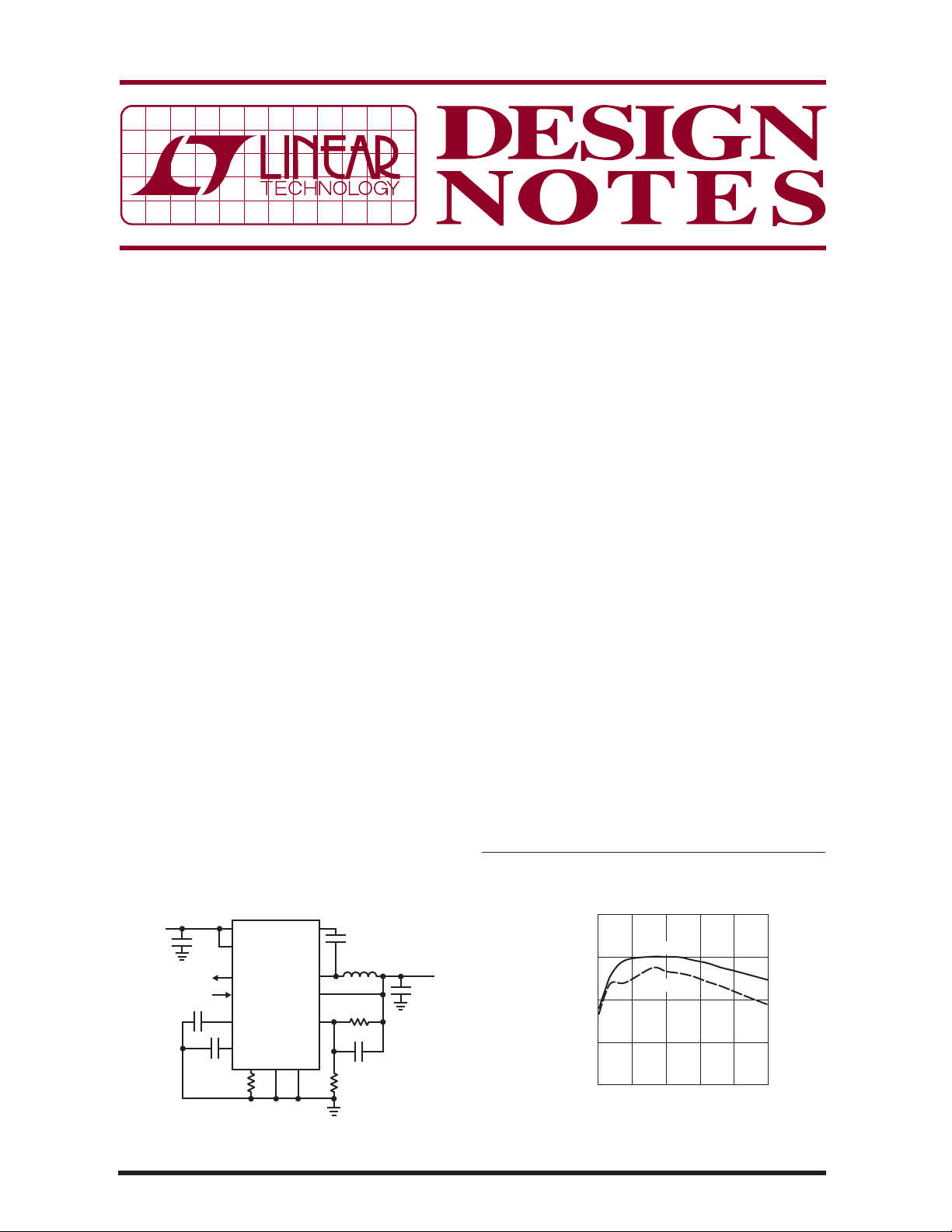
portion of the output voltage. Figure 1 shows a 12V
to 3.3V circuit. Figure 2 shows the effi ciency of this
circuit reaching 94%, which is 5% to 10% higher than
a comparable nonsynchronous circuit.
Short-Circuit Robustness Using Small Inductors
The LT8610 and LT8611 are specifi cally designed to
minimize solution size by allowing inductor size to be
selected based on the output load requirements of the
application, rather than the maximum current limits of
the IC. During overload or short-circuit conditions, the
LT8610 and LT8611 safely tolerate operation with saturated inductors through the use of a high speed peakcurrent mode architecture and a robust switch design.
For example, an application that requires a maximum
of 1.5A should use an inductor that has an RMS rating
of >1.5A and a saturation current rating of >1.9A. This
fl exibility allows the user to avoid oversize inductors for
applications re quiring less than maximum outpu t current.
Current Sense and Monitoring with the LT8611
The LT8611 includes a fl exible current control and
monitor loop using the ISN, ISP, IMON and ICTRL pins.
The ISP and ISN pins connect to an external sense
resistor that may be in series with the input or output
of the LT8611 or in series with other system currents.
The current limit loop functions by limiting the LT8611
output current such that the voltage between the ISP
L, LT, LTC, LTM, Linear Technology, the Linear logo and μModule are registered
trademarks of Linear Technology Corporation. All other trademarks are the property
of their respective owners.
3.8V TO 42V
07/12/504
V
IN
4.7μF
10nF
1μF
f
60.4k
= 700kHz
SW
IN
EN/UV
PG
SYNC
TR/SS
INTV
RT
CC
LT8610
PGND
GND
BSTV
SW
BIAS
0.1μF
L1
4.7μH
FB
1M
4.7pF
412k
Figure 1. LT8610 12V to 3.3V Application
Achieves High Effi ciency
V
OUT
3.3V
C1
2.5A
47μF
L1: HCM0703-4R7, COILTRONICS
C1: GRM32ER71A476K, MURATA
dn504 F01
100
95
90
EFFICIENCY (%)
85
80
0
VO = 5V
VO = 3.3V
LOAD CURRENT (A)
2.51.0 2.00.5 1.5
dn504 F02
Figure 2. Effi ciency of the 12V to 3.3V Application
(Circuit Shown in Figure 1)
Page 2
and ISN pins does not exceed 50mV. The ICTRL pin
allows the user to control this limit between 0mV and
50mV b y ap ply ing 0V t o 1V to t he IC TR L pin . Th e IMO N
pin outputs a ground-referenced voltage that is 20 •
(ISP – ISN), which allows easy monitoring and may be
used as an input to an A/D.
The LT8611 current sense and monitoring functionality
may be used to limit short-circuit current or to create
constant-current, constant-voltage (CCCV) supplies.
Figure 3 shows well controlled current during a shortcircuit event. The LT8611 can also be combined with a
microcontroller wi th A/D and D/A to create sophis ticated
power systems. Typical apps include maximum power
point tracking (MPPT) for solar charging and programmable LED current source.
5W
20V/DIV
INDUCTOR
CURRENT
1A/DIV
dn504 F03
Figure 3. Short-Circuit Current is Well Regulated at 42V
with the LT8611
V
5.4V TO 42V
IN
4.7μF
μP
OPTIONAL
1μF
0.1μF
IN
EN/UVON OFF
SYNC
IMON
ICTRL
INTV
TR/SS
RT
18.2k
LT8611
CC
BSTV
0.1μF
V
SW
ISP
ISN
BIAS
PG
FB
GNDPGND
L1
3.3μH
0.025Ω
10pF
1M
243k
dn504 F04
5V
2A
C1
47μF
OUT
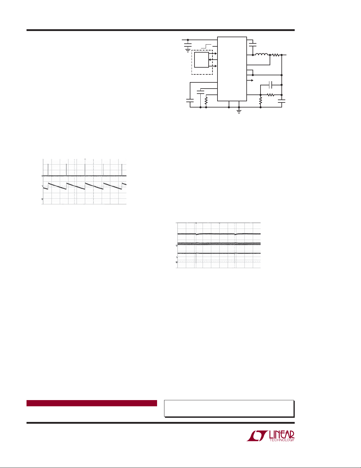
Figure 4. LT8611 Running at 2MHz Reduces Solution
Size, Avoids AM Band, and Still Allows High Duty Cycle
Low Dropout Operation
As the input volt age decreases toward the programmed
o u t p u t v o l t a g e , t h e L T 8 6 10 a n d L T 8 6 11 m a i n t a i n r e g u l a tion by skipping switch-off times and decreasing the
switching frequency up to a maximum duty cycle of
99.8%. If the input voltag e decreases further, the output
voltage remains 450mV below the input voltage (at 2A
load). The boost capacitor is charged during dropout
conditions, maintaining high effi ciency. Figure 5 shows
the dropout performance.
Wide Input Range Operation at 2MHz
It is well known that higher switching frequencies allow
for smaller solution sizes. In fact, a 2MHz switching
frequency is often used in automotive applications to
avoid the AM band and minimize solution footprint.
High switching frequencies, though, come with some
trade-offs, including reduced ability to handle wide
input voltage range commonly found in automotive
and industrial environments. However, the LT8610 and
LT8611 minimize these restrictions by allowing both
high switching frequencies and high conversion ratios.
This is due to their low minimum on-times (50ns typical) and low dropout, resulting in a wide input range,
even at 2MHz. Figure4 shows a 5V, 2A, 2MHz circuit
that can accept 5.4V to 42V inputs. The circuit has a
2A output current limit.
Data Sheet Download
www.linear.com
= 500mA/DIV
I
L
VIN = 1V/DIV
V
= 1V/DIV
O
= 2V/DIV
V
SW
dn504 F05
Figure 5. LT8610/LT8611 Dropout Performance
Conclusion
LT8610 and LT8611 are 42V, 2.5A synchronous stepdown regulators that offer 2.5μA quiescent current,
high effi ciency, fault robustness and constant current
(LT8611 only), constant voltage operation in small
packages. This combination of features makes them
ideal for the harsh environment commonly found in
automotive and industrial applications.
For applications help,
call (408) 432-1900, Ext. 3513
Linear Technology Corporation
1630 McCarthy Blvd., Milpitas, CA 95035-7417
(408) 432-1900
●
FAX: (408) 434-0507 ● www.linear.com
dn504f LT/AP 0712 196K • PRINTED IN THE USA
© LINEAR TECHNOLOGY CORPORATION 2012
 Loading...