

Monitor and Protect Automotive Systems with Integrated
Current Sensing –
Design Note 374
John Munson
Introduction
An automobile is an unforgiving environment for integrated circuits, where under-the-hood operating temperatures run from –40°C to 125°C and large transient
excursions on the battery voltage bus are expected. In the
past, electronics were part of the well-protected and
centralized Engine Control Unit (ECU), but the trend is
toward more distributed electronics. Electrically driven
accessories and fault-protection monitoring functions are
leaving the protective umbrella of the ECU and migrating
directly into vehicle subsystems.
For example, many functions formerly driven by the
engine—via belt and pulley or hydraulics—are now electrically driven (motorized), such as water pumps, steering
mechanisms, brake actuators and various body controls.
These functions can become a safety risk if they are not
continually monitored for operational readiness and/or
have a back-up mode of operation. In either case, realtime monitoring becomes necessary and generally
involves accurately measuring the current draw of each
subsystem.
Simple Current Monitoring Solutions
The LT®6100 and LTC6101 are high side current-sense
amplifiers that have been developed specifically to address
the automotive designers’ needs. These parts require a
minimum number of support components to operate in
the harsh automotive battery-bus environment.
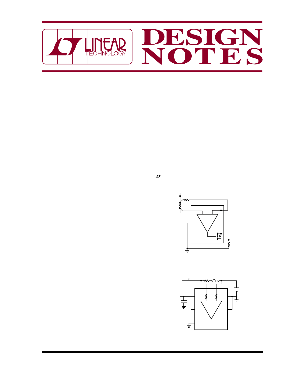
Figure 1 shows a basic high side current monitor using the
LTC6101. The selection of R
desired gain of this circuit, powered directly from the
battery bus. The current output of the LTC6101 allows it
to be located remotely to R
placed directly at the shunt, while R
monitoring electronics without ground drop errors.
This circuit has a fast 1µs response time that makes it ideal
for providing MOSFET load switch protection. The switch
element may be the high side type connected between the
sense resistor and the load, a low side type between the
and R
IN
. Thus, the amplifier can be
OUT
establishes the
OUT
is placed near the
OUT
load and ground or an H-bridge. The circuit is programmable to produce up to 1mA of full-scale output current
into R
, yet draws a mere 250µA supply current when
OUT
the load is off.
Figure 2 shows the LT6100 used as a combination
current sensor and fuse monitor. This part includes onchip output buffering and was designed to operate with
the low supply voltage (≥2.7V), typical of vehicle data
acquisition systems, while the sense inputs monitor
signals at the higher battery bus potential. The LT6100
, LTC and LT are registered trademarks of Linear Technology Corporation.
All other trademarks are the property of their respective owners.
BATTERY BUS
R
R
0.01Ω
POWER
Figure 2. Simple LT6100 High Side Current Sense
Amplifier and Fuse Monitor
IN
SENSE
LOAD
100Ω
4
+
2
LT6101
= I
V
OUT
LOAD(RSENSE
3
–
5
1
R
OUT
4.99k
• R
)
OUT/RIN
DN374 F01
Figure 1. Simple LTC6101 High Side
Current Sense Amplifier
R
SENSE
FUSE
2mΩ
A4
A2
OUT
DN374 F02
7
6
5
+
OUTPUT
2.5V = 25A
81
–
+
V
V
S
–
LT6100
S
+
2
V
CC
3
FIL
4
V
EE
ADC
≥2.7V
TO LOAD
C2
0.1µF
V
OUT
4.99V = 10A
BATTERY
BUS
10/05/374
inputs are tolerant of large input differentials, thus allowing the blown-fuse operating condition (this would be
detected by an output full-scale indication). The LT6100
can also be powered down while maintaining high impedance sense inputs, drawing less than 1µA max from the
battery bus.
Solving the H-Bridge Problem
Many of the newer electric drive functions, such as
steering assist, are bidirectional in nature. These functions are generally driven by H-bridge MOSFET arrays
using pulse-width-modulation (PWM) methods to vary
the commanded torque. In these systems, there are two
main purposes for current monitoring. One is to monitor
the current in the load, to track its performance against the
desired command (i.e., closed-loop servo law), and
another is for fault detection and protection features.
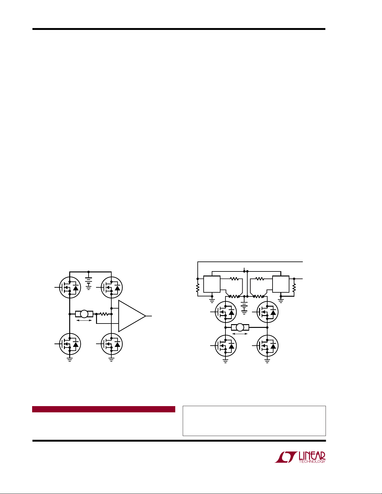
A common monitoring approach in these systems is to
amplify the voltage on a “flying” sense resistor, as shown
in Figure 3. Unfortunately, several potentially hazardous
fault scenarios go undetected, such as a simple short to
ground at a motor terminal. Another complication is the
noise introduced by the PWM activity. While the PWM
noise may be filtered for purposes of the servo law,
information useful for protection becomes obscured. The
best solution is to simply provide two circuits that individually protect each half-bridge and report the bidirectional load current. In some cases, a smart MOSFET
bridge driver may already include sense resistors and
offer the protection features needed. In these situations,
the best solution is the one that derives the load information with the least additional circuitry.
Figure 4 shows a differential load measurement for an
ADC using twin unidirectional sense measurements. Each
LTC6101 performs high side sensing that rapidly responds
to fault conditions, including load shorts and MOSFET
failures. Hardware local to the switch module (not shown
in the diagram) can provide the protection logic and furnish a status flag to the control system. The two LTC6101
outputs taken differentially produce a bidirectional load
measurement for the control servo. The ground-referenced signals are compatible with most ∆Σ ADCs. The ∆Σ
ADC circuit also provides a “free” integration function that
removes PWM content from the measurement. This
scheme also eliminates the need for analog-to-digital
conversions at the rate needed to support switch protection, thus reducing cost and complexity.
Conclusion
The LT6100 and LTC6101 high side current-sense amplifiers simplify designs in the automotive environment.
High transient voltage tolerance (105V for the LTC6101HV)
and ground-referenced outputs make it possible to
improve robustness and substantially reduce the partscount over traditional solutions.
R
–
DIFF
OUTPUT
TO ADC
+
OUT
BATTERY BUS
+
BATTERY BUS
R
LTC6101
R
OUT
IN
R
S
R
IN
LTC6101
R
S
+
RANGE = ±100A,
+
R
S
I
M
DN374 F03
DIFF
AMP
–
I
M
FOR I
DIFF OUT = ±2.5V
R
R
R
DN374 F04
= 1mΩ
S
= 200Ω
IN
OUT
M
= 4.99k
Figure 3. Limited Performance H-Bridge Current Monitor Figure 4. Practical H-Bridge Current Monitor Offers
Fault Detection and Bidirectional Load Information
Data Sheet Download
http://www.linear.com
For applications help,
call (408) 432-1900, Ext. 2020
Linear Technology Corporation
1630 McCarthy Blvd., Milpitas, CA 95035-7417
(408) 432-1900 ● FAX: (408) 434-0507 ● www.linear.com
dn374f LT/TP 1005 409K • PRINTED IN THE USA
© LINEAR TECHNOLOGY CORPORATION 2005
 Loading...